CN216846394U - Removable housing apparatus for coriolis mass flowmeter - Google Patents
Removable housing apparatus for coriolis mass flowmeter Download PDFInfo
- Publication number
- CN216846394U CN216846394U CN202122733047.7U CN202122733047U CN216846394U CN 216846394 U CN216846394 U CN 216846394U CN 202122733047 U CN202122733047 U CN 202122733047U CN 216846394 U CN216846394 U CN 216846394U
- Authority
- CN
- China
- Prior art keywords
- sealing
- mass flowmeter
- detachable shell
- supporting tube
- coriolis force
- Prior art date
- Legal status (The legal status is an assumption and is not a legal conclusion. Google has not performed a legal analysis and makes no representation as to the accuracy of the status listed.)
- Expired - Fee Related
Links
Images


Landscapes
- Measuring Volume Flow (AREA)
Abstract
The utility model relates to a detachable shell device of a Coriolis force mass flowmeter, which consists of a detachable shell, a supporting tube, a connecting bolt and a sealing strip, wherein the outer surface of the lower part of the supporting tube is mutually matched and connected with the inner surface of the upper part of the detachable shell through respective connecting sealing surfaces, and the sealing joint is fixed by the connecting bolt after the sealing strip is arranged at the sealing joint to form sealing connection. The utility model adopts the detachable shell device which is sealed by the upper and lower inclined planes and the sealing strips, can repeatedly install the detachable shell on the supporting tube or detach the detachable shell from the supporting tube under the condition of ensuring the sealing property and the waterproof property of the cavity in the Coriolis force mass flowmeter, and solves the problems of online detection and replacement during calibration of the Coriolis force mass flowmeter and online detection and maintenance property under working conditions. Meanwhile, the sealing strip is used, so that the connection between the detachable shell and the supporting tube is changed into flexible connection, partial external transmission is eliminated and absorbed, and the reliability of the accuracy of the Coriolis force mass flowmeter is improved.
Description
Technical Field
The present invention relates to a coriolis mass flowmeter, and more particularly, to a removable housing device of a coriolis mass flowmeter.
Background
Currently, the coriolis mass flowmeter has become a flow meter with the most precise accuracy in flow measurement, and the accuracy of a general flow meter is as follows: the liquid (water or oil) measures 1 and 0.5 grades and the gas measures 1.0 and 1.5 grades. Coriolis force mass flowmeters can be accurate to liquid measurements on the order of 0.1 and 0.2 and gas measurements on the order of 0.2 and 0.3. And no movable or rotary part is arranged in the whole measuring circulation pipeline, the operation can be reliable for a long time, the requirement on a measured medium is low, and the requirement on front and rear straight pipe sections of a measuring pipeline is low. Coriolis force mass flowmeters are rapidly and extensively used in a variety of industrial and utility applications. At present, the coriolis force mass flow meter adopts a totally-enclosed design, i.e., a closed shell is directly welded on a supporting tube, a flow measuring tube, which is a main part for measurement, is closed in the supporting tube, and a driving coil (for starting initial vibration), a detecting coil (for detecting a flow signal), a connecting wire, a damping plate, a balancing weight and the like are all arranged on the flow measuring tube. The flow measuring tube is brazed to the branch fluid outlet of the support tube. The measured fluid flows in from the front branch fluid, passes through the flow measuring tube and then flows out from the rear branch fluid, a full-through hollow tube is arranged between the flow measuring tube and the rear branch fluid, no movable or rotating part is arranged, and the measured fluid is not in direct contact with a detection part (a driving coil and a detection coil). So when calibration is not acceptable, or there are problems in use, the split flow and flow measurement tube are generally not problematic, and problems generally arise: the driving coil and the detection coil are damaged or are not properly arranged, the connecting line is damaged, the position of the damping plate is not proper, and the weight is not proper or is not properly arranged. When the problems occur, the Coriolis force mass flowmeter is dismounted from a pipeline and returned to an assembly workshop for shell opening treatment, maintenance and re-weighting, the workload is large, time and labor are wasted, the original shell cannot be used, the Coriolis force mass flowmeter after being re-mounted has the possibility of unqualified calibration when being re-calibrated, and the Coriolis force mass flowmeter needs to be re-shelled again. All flow measuring instruments except the coriolis force mass flowmeter are in contact with a measured fluid whether the detecting components are movable or fixed, and must be detached from a pipeline for maintenance.
Disclosure of Invention
In view of the problems caused by the totally enclosed design of the Coriolis force mass flowmeter, the utility model provides a detachable shell device of Coriolis force mass flow rate, which is safe, reliable, simple in structure and easy to produce.
In order to realize the purpose, the technical scheme of the utility model is as follows: a detachable shell device of a Coriolis force mass flowmeter comprises a detachable shell, a supporting tube, a connecting bolt and a sealing strip, wherein the outer surface of the lower portion of the supporting tube is connected with the inner surface of the upper portion of the detachable shell in a matched mode through respective connecting sealing surfaces, and the sealing strip is arranged at the sealing connection position to be fixed through the connecting bolt after being connected in a sealing mode.
Furthermore, the connection sealing surface of the supporting tube and the connection sealing surface of the detachable shell are inclined surfaces.
Further, the inclination of the inclined plane is 5 degrees.
Further, the height of the inclined plane is 15-50 mm.
Furthermore, a sealing groove is formed in the supporting tube connecting sealing surface and used for installing a sealing strip.
Furthermore, a row of connecting screw holes is formed above the sealing groove.
The utility model has the beneficial effects that: under normal operating mode condition, under the leakproofness and the waterproof nature circumstances of cavity in guaranteeing Coriolis force mass flowmeter, adopted the upper and lower inclined plane to add the detachable shell device that the sealing strip carries out sealedly, can be easy, repeated will dismantle the shell and install on the stay tube or dismantle from the stay tube to expose flow measurement buret, damping plate, balancing weight, drive coil, detection coil, line etc. easily detect, maintain, change. The problem of online detection and replacement during calibration of the Coriolis force mass flowmeter is solved, and online detection and maintenance performance under the working condition of the Coriolis force mass flowmeter are solved. Meanwhile, the sealing strips are used, so that the connection between the detachable shell and the supporting tube is changed into flexible connection (originally, the connection is welded and rigid), partial external transmission (shell vibration and supporting tube vibration which are mutually transmitted between the shell and the supporting tube) is eliminated and absorbed, and the reliability of the accuracy of the Coriolis force mass flowmeter is improved.
The purpose of the utility model is achieved.
Drawings
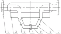
FIG. 1 is a schematic view of the distribution of components of a chamber in a Coriolis force mass flowmeter;
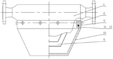
FIG. 2 is a front view of the removable housing apparatus of the present invention;
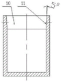
FIG. 3 is a front view of a closure housing of the removable housing apparatus of the present invention;
FIG. 4 is a left side elevational view of the closure housing of the removable housing apparatus of the present invention;
FIG. 5 is a front elevational view of the support tube of the removable housing apparatus of the present invention;
in the figure: 1-supporting tube, 2-shunt body, 3-detection coil, 4-driving coil, 5-flow measuring tube, 6-balancing weight, 7-damping plate, 8-connecting bolt, 9-sealing strip, 10-detachable shell, 11-detachable shell connecting sealing inclined plane, 12-supporting tube connecting sealing inclined plane, and 13-sealing groove.
Detailed Description
The utility model is further described with reference to the following figures and examples.
As shown in fig. 1, the coriolis mass flowmeter includes a support tube 1, a flow distribution body 2, a detection coil 3, a drive coil 4, a flow measurement tube 5, a weight block 6, a damping plate 7, a connection bolt 8, a sealing strip 9, a detachable housing 10, a detachable housing connection sealing inclined surface 11, a support tube connection sealing inclined surface 12, and a sealing groove 13.
As shown in fig. 2 to 5, the detachable shell assembly of the present invention is mainly composed of a detachable shell 10, a support pipe 1, a connecting bolt 8, and a seal strip 9. The original closed shell directly welded on the supporting tube 1 is not connected by adopting a welding process, but the outer surface of the lower part of the supporting tube 1 and the inner surface of the opening of the detachable shell 10 are both processed and milled with a connecting sealing surface with the width of 15-50mm (different according to different calibers and different widths). And on the supporting tube 1 connecting sealing surface, a sealing groove 13 is milled for installing a sealing strip 9 to ensure the sealing property and the water resistance of the inner cavity. A row of connecting bolts 8 (the number of bolts and the diameter are different depending on the diameter) is installed above the seal groove 13.
In order to ensure the sealing performance and the waterproof performance of the sealing surface, the connecting sealing surface of the supporting tube 1 and the detachable shell 10 is processed by adopting inclined planes. The detachable shell 10 is attached with a detachable shell connecting sealing inclined surface 11, and the support pipe 1 is attached with a support pipe connecting sealing inclined surface 12 and a sealing groove 13. During installation, the detachable shell connecting sealing inclined plane 11 is matched and connected with the support pipe 1 and a support pipe connecting sealing inclined plane 12 is attached to connect the sealing strip 9, and the sealing strip 9 is placed in a sealing groove 13 on the support pipe connecting sealing inclined plane 12.
Preferably, the slope height of the detachable housing joint sealing slope 11 and the support pipe joint sealing slope 12 is 15-50 mm.
Preferably, the slope of the detachable housing joint seal slope 11 and the support tube joint seal slope 12 is 5 degrees.
When the Coriolis force mass flowmeter is assembled, the assembly is carried out according to the original assembly process, after the damping plate 7, the balancing weight 6, the driving coil 4, the detection coil 3, the connecting wire and the like are assembled, welding is not carried out any more, but the sealing strip 9 is installed in the sealing groove 13 on the sealing surface 12 of the supporting tube connection at the lower part of the supporting tube 1, the sealing surface 12 of the supporting tube connection on the detachable shell sleeve is further connected, and after the sealing surface 12 of the shell connection surface 11 and the supporting tube connection in the detachable shell 10 is tight, the connecting bolt 8 is installed and screwed down.
During installation, attention needs to be paid to: the detachable shell connecting and sealing inclined plane 11 is slowly and uniformly sleeved on the supporting tube connecting and sealing inclined plane 12 which is provided with the sealing strip 9 all around, the gap between the two inclined planes is gradually reduced until the sealing strip 9 is compacted to realize the sealing function, and then the connecting bolts 8 are screwed up one by one relatively, so that the detachable shell 10 is tightly connected with the supporting tube 1 through the sealing strip 9, and the inner cavity of the Coriolis force mass flowmeter is an enclosed space.
Claims (6)
1. A removable housing apparatus for a coriolis mass flowmeter, comprising: the sealing device is characterized by comprising a detachable shell, a supporting pipe, a connecting bolt and a sealing strip, wherein the outer surface of the lower part of the supporting pipe is matched and connected with the inner surface of the upper part of the detachable shell through respective connecting and sealing surfaces, and the sealing strip is arranged at the sealing connection part to form sealing connection and then is fixed by the connecting bolt.
2. The removable housing assembly of a coriolis mass flowmeter of claim 1 characterized in that: the connection sealing surface of the supporting tube and the connection sealing surface of the detachable shell are inclined planes.
3. The removable housing assembly of a coriolis mass flowmeter of claim 2 further comprising: the slope of the inclined plane is 5 degrees.
4. The removable housing assembly of a coriolis mass flowmeter of claim 2 further comprising: the height of the inclined plane is 15-50 mm.
5. The removable housing assembly of a coriolis mass flowmeter of claim 1 characterized in that: and a sealing groove is formed in the connecting sealing surface of the supporting tube and used for installing a sealing strip.
6. The removable housing assembly of a coriolis mass flowmeter of claim 5 characterized in that: and a row of connecting screw holes are formed above the sealing groove.
Priority Applications (1)
| Application Number | Priority Date | Filing Date | Title |
|---|---|---|---|
| CN202122733047.7U CN216846394U (en) | 2021-11-09 | 2021-11-09 | Removable housing apparatus for coriolis mass flowmeter |
Applications Claiming Priority (1)
| Application Number | Priority Date | Filing Date | Title |
|---|---|---|---|
| CN202122733047.7U CN216846394U (en) | 2021-11-09 | 2021-11-09 | Removable housing apparatus for coriolis mass flowmeter |
Publications (1)
| Publication Number | Publication Date |
|---|---|
| CN216846394U true CN216846394U (en) | 2022-06-28 |
Family
ID=82102303
Family Applications (1)
| Application Number | Title | Priority Date | Filing Date |
|---|---|---|---|
| CN202122733047.7U Expired - Fee Related CN216846394U (en) | 2021-11-09 | 2021-11-09 | Removable housing apparatus for coriolis mass flowmeter |
Country Status (1)
| Country | Link |
|---|---|
| CN (1) | CN216846394U (en) |
Cited By (2)
| Publication number | Priority date | Publication date | Assignee | Title |
|---|---|---|---|---|
| CN113932864A (en) * | 2021-11-09 | 2022-01-14 | 锐莱特仪表(上海)有限公司 | Vibration absorbing device of Coriolis force mass flowmeter |
| CN113984136A (en) * | 2021-11-09 | 2022-01-28 | 锐莱特仪表(上海)有限公司 | Detachable casing device of Coriolis force mass flowmeter |
-
2021
- 2021-11-09 CN CN202122733047.7U patent/CN216846394U/en not_active Expired - Fee Related
Cited By (2)
| Publication number | Priority date | Publication date | Assignee | Title |
|---|---|---|---|---|
| CN113932864A (en) * | 2021-11-09 | 2022-01-14 | 锐莱特仪表(上海)有限公司 | Vibration absorbing device of Coriolis force mass flowmeter |
| CN113984136A (en) * | 2021-11-09 | 2022-01-28 | 锐莱特仪表(上海)有限公司 | Detachable casing device of Coriolis force mass flowmeter |
Similar Documents
| Publication | Publication Date | Title |
|---|---|---|
| CN113984136A (en) | Detachable casing device of Coriolis force mass flowmeter | |
| CN112729420B (en) | Non-full pipe flowmeter and installation and use method thereof | |
| CN219736455U (en) | Visual wedge flowmeter | |
| CN202836631U (en) | Single-pipe buchholz relay detecting platform and centring clamping mechanism special for buchholz relay detection | |
| CN218097883U (en) | Cleaning equipment of ultrasonic flowmeter | |
| CN208333627U (en) | A kind of fluid flowmeter on-line checking self-calibrating device | |
| CN105486359A (en) | Flow velocity and pressure integral measuring instrument using Pitot tube method | |
| CN202421014U (en) | Slurry density-measuring unit | |
| CN209459712U (en) | Ultrasonic water meter | |
| CN206609484U (en) | A kind of ultrasonic flowmeter | |
| CN217716887U (en) | Test bench for detecting oil circuit system | |
| CN211651707U (en) | Thermal Gas Mass Flow Meters | |
| RU205140U1 (en) | Condensing device, diaphragm type, quick-change (USDB) | |
| CN209512940U (en) | A New Orifice Flowmeter | |
| CN110987092A (en) | Multiphase flow vortex shedding flowmeter in pit | |
| CN210774200U (en) | High-temperature ultrasonic flowmeter measuring device capable of adding coupling agent | |
| CN223319844U (en) | A vortex flowmeter | |
| CN223389227U (en) | Simple spliced delta wing flow meter | |
| CN223412767U (en) | Worm gear flowmeter convenient to assemble | |
| CN223896859U (en) | Small-caliber plug-in vortex street sensor | |
| CN222144221U (en) | A bidirectional flow meter | |
| CN220871811U (en) | Built-in V-cone flowmeter easy to maintain | |
| CN222050252U (en) | Integrated flowmeter calibration and detection device | |
| CN222926247U (en) | Instrument for measuring fluid flow in pipeline | |
| CN211651699U (en) | Vortex flowmeter |
Legal Events
| Date | Code | Title | Description |
|---|---|---|---|
| GR01 | Patent grant | ||
| GR01 | Patent grant | ||
| CF01 | Termination of patent right due to non-payment of annual fee |
Granted publication date: 20220628 |
|
| CF01 | Termination of patent right due to non-payment of annual fee |