SUMMERY OF THE UTILITY MODEL
The utility model aims to provide a high-voltage cable outer sheath and metal sheath nondestructive circular cutting device, which can realize automatic circular cutting of the high-voltage cable outer sheath and/or the metal sheath and has the advantages of improving cutting quality and reducing labor intensity of workers.
The utility model adopts the following technical scheme:
a high-voltage cable outer sheath and metal sheath nondestructive circular cutting device comprises a sliding table device, a circular cutting fixing device, a circular cutting rotating device, a circular cutting tool and a control system; the sliding table device is detachably arranged outside the cable to be subjected to circular cutting through a cable fixing device, and the circular cutting fixing device is connected with the lower surface of the sliding table device in a sliding mode through a horizontal moving device; the circular cutting fixing device is coaxially provided with a rotary accommodating cavity along the front and back direction, a circular cutting rotating device is coaxially and rotatably arranged in the rotary accommodating cavity, and the circular cutting rotating device is driven by the rotary driving device to rotate in the rotary accommodating cavity; the circular cutting rotating device is coaxially provided with a cable accommodating cavity along the front-back direction, and a cable to be circular cut is coaxially arranged in the cable accommodating cavity of the circular cutting rotating device; the circular cutting tool is fixed on the front side surface of the circular cutting rotating device and synchronously rotates along with the circular cutting rotating device, a circular cutting tool bit driven by the linear driving device is arranged in the circular cutting tool, and the circular cutting tool bit is used for circularly cutting a cable to be circularly cut; the control system is respectively connected with the horizontal moving device, the rotary driving device and the linear driving device in a control mode and respectively controls the horizontal movement of the circular cutting fixing device, the rotation of the circular cutting rotating device and the stretching of the circular cutting head.
The cable fixing device comprises cable clamps which are respectively arranged in front of and behind the circular cutting fixing device, each cable clamp comprises an upper threaded rod and a lower threaded rod, the lower end of each upper threaded rod and the upper end of each lower threaded rod are respectively and rotatably provided with an arc-shaped clamping part matched with the outer wall of the cable to be circularly cut, and the upper ends of the two upper threaded rods are respectively in threaded connection with the front part and the rear part of the sliding table device; the lower ends of the two lower threaded rods are respectively in threaded connection with corresponding threaded sleeves, and a circular cutting fixing device sliding rod is horizontally arranged between the two threaded sleeves.
The horizontal moving device adopts a ball screw; the front end and the rear end of a screw in the ball screw are respectively and rotatably connected with the front part and the rear part of the sliding table device through screw bearings, a sliding table sliding block is arranged on the lower surface of the sliding table device in a sliding manner, the lower end of the sliding table sliding block is fixed on the upper end surface of the circular cutting fixing device, and the screw is driven by a screw motor which is coaxially connected; the circular cutting fixing device is sleeved outside the sliding rod of the circular cutting fixing device.
The circular cutting fixing device is coaxially provided with a circular rotary accommodating cavity of which two ends are communicated with the outside along the front and back directions, the circular cutting rotating device is a circular ring of which the outer diameter is matched with that of the rotary accommodating cavity, and the circular cutting rotating device is rotationally connected with the rotary accommodating cavity through a circular cutting bearing; the rotary driving device is arranged on the rear side surface of the upper end of the circular cutting fixing device; the output end of the rotary driving device is arranged downwards, the end part of the rotary driving device is provided with a driving bevel gear, the rear side surface of the circular cutting rotating device is coaxially provided with an annular driven bevel gear, and the driving bevel gear is meshed with the driven bevel gear.
The circular cutting tool is fixed on the front side surface of the upper end of the circular cutting rotating device, and the circular cutting tool bit is driven by the linear driving device to move upwards or downwards; the circular cutting tool comprises a hollow mounting shell, an opening at the upper end of the mounting shell is provided with an end cover, and the end cover is connected with the mounting shell through a feeding fixing screw; the lower surface of the end cover is provided with a driving device mounting seat, the linear driving device is vertically arranged in the driving device mounting seat, feeding guide rails are arranged in mounting shells on two sides of the driving device mounting seat, the lower ends of the feeding guide rails are connected with the lower end of the mounting shell through threads, the upper end parts of the feeding guide rails penetrate through the end cover and are positioned outside the end cover, sliding tool holders are arranged on the two feeding guide rails below the linear driving device in a sliding mode, springs are arranged on the feeding guide rails between the sliding tool holders and the end cover, and the upper ends and the lower ends of the springs are respectively connected with the lower surface of the end cover and the upper surface of the sliding tool holders; a pressure sensor groove is formed in the position, corresponding to the output shaft of the linear driving device, of the upper surface of the sliding cutter holder, a pressure sensor is arranged in the pressure sensor groove, a cutter propelling sleeve is arranged on the output shaft of the linear driving device, the outer diameter of the cutter propelling sleeve is matched with the inner diameter of the pressure sensor groove, the stress detection end of the pressure sensor is in contact with the lower end of the cutter propelling sleeve when the cable is subjected to circular cutting, and the signal output end of the pressure sensor is connected with the signal input end of a control system; the lower surface of the sliding cutter holder is in threaded connection with the circular cutting head through a threaded hole, and the end part of the lower end of the circular cutting head penetrates through the mounting shell through a cutter head through hole formed in the lower end of the mounting shell.
The front side surface of the circular cutting fixing device is provided with four concentrically arranged annular power supply conducting bars connected with a power supply, and the rear side surfaces of the four annular power supply conducting bars are adhered to the surface of the circular cutting fixing device through matched annular insulating sheets; the A + pole, A-pole, B + pole and B-pole terminals of the linear driving device are respectively contacted with the corresponding annular power supply conducting strips through metal rolling wheels.
The annular power supply conducting bar is arranged on the front side surface or the rear side surface of the circular cutting fixing device, and when the annular power supply conducting bar is arranged on the front side surface of the circular cutting fixing device, the wiring end of the linear stepping motor directly contacts with the corresponding annular power supply conducting bar through the metal rolling wheel; when the annular power supply conducting bar is arranged on the rear side surface of the circular cutting fixing device, the wiring end of the linear stepping motor passes through the circular cutting fixing device by using a conducting wire and then is contacted with the corresponding annular power supply conducting bar through a metal rolling wheel arranged on the rear side surface of the circular cutting fixing device.
The color recognition device comprises a rotary device connecting block fixedly arranged on the front side surface of the circular cutting rotary device, a color recognition threaded rod is arranged in the rotary device connecting block in a vertical threaded manner, the upper end of the color recognition threaded rod is connected with a color recognition sensor mounting box in a threaded manner, an observation window and a key are arranged on the color recognition sensor mounting box, the color recognition sensor is arranged in the color recognition sensor mounting box, and the signal output end of the color recognition sensor is connected with the signal input end of the control system; the end part of the color identification threaded rod is provided with a handle.
The ring-cutting tool bit comprises an outer sheath ring-cutting tool bit and a metal sheath ring-cutting tool bit;
the outer sheath circular cutting head comprises an outer sheath circular cutting head connecting screw and an outer sheath circular cutting head body which are integrally arranged, the lower end face of the outer sheath circular cutting head body is an inverted triangular pyramid, one side face of the triangular pyramid is perpendicular to the bottom face, and edges of three side faces of the triangular pyramid are cutting edges;
the metal sheath circular cutting tool bit comprises an integrally arranged metal sheath circular cutting tool bit connecting screw and a metal sheath circular cutting tool bit body, wherein the lower end face of the metal sheath circular cutting tool bit body is provided with a cutting edge, and a plurality of sawteeth are uniformly arranged on the cutting edge.
The utility model realizes the fixation of the circular cutting fixing device and the cable to be circularly cut through the cable clamp, and identifies the circular cutting position marked by colors on the cable to be circularly cut through the color identification device so as to ensure the accuracy of the circular cutting operation position. In the ring cutting process, the continuous rotation of the ring cutting tool in the circumferential direction of the cable to be ring cut is realized through the ring cutting rotating device and the rotating driving device; and the radial cutter feeding control of the circular cutting cutter is accurately realized through the linear driving device, and finally the circular cutting work of the cable to be subjected to circular cutting is completed in a matching manner. In the utility model, the pressure variable acquired by the pressure sensor is analyzed, whether the cutter touches the metal sheath or the radial water-blocking tape or not is judged by judging whether the pressure is abnormal or not, and the cutter is retracted in time, so that nondestructive circular cutting is realized, and the circular cutting quality is improved. The replaceable circular cutting tool bit is arranged, so that the corresponding circular cutting tool bit is selected according to an object to be circularly cut, and the practicability and the universality of the circular cutting tool are improved.
Detailed Description
The utility model is described in detail below with reference to the following figures and examples:
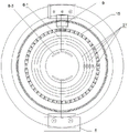
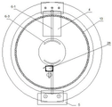
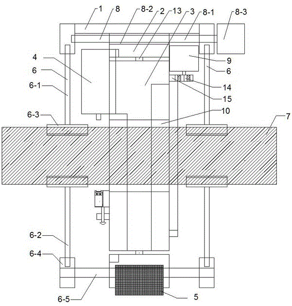
as shown in fig. 1 to 8, the high-voltage cable outer sheath and metal sheath nondestructive circular cutting device of the utility model comprises a sliding table device 1, a circular cutting fixing device 2, a circular cutting rotating device 3, a circular cutting tool 4 and a control system 5;
the sliding table device 1 is detachably arranged outside a cable 7 to be subjected to circular cutting through a cable fixing device 6, and the circular cutting fixing device 2 is connected with the lower surface of the sliding table device 1 in a sliding mode through a horizontal moving device 8; the circular cutting fixing device 2 is coaxially provided with a rotary accommodating cavity along the front and back direction, a circular cutting rotating device 3 is coaxially and rotatably arranged in the rotary accommodating cavity, and the circular cutting rotating device 3 is driven by a rotary driving device 9 to rotate in the rotary accommodating cavity; the circular cutting rotating device 3 is coaxially provided with a cable accommodating cavity 10 along the front and back direction, and the cable 7 to be circular cut is coaxially arranged in the cable accommodating cavity 10 of the circular cutting rotating device 3; the circular cutting tool 4 is fixed on the front side surface of the circular cutting rotating device 3 and synchronously rotates along with the circular cutting rotating device 3, a circular cutting head 12 driven by a linear driving device 11 is arranged in the circular cutting tool 4, and the circular cutting head 12 is used for circularly cutting the cable 7 to be circularly cut; the control system 5 is respectively connected with the horizontal moving device 8, the rotary driving device 9 and the linear driving device 11 and respectively controls the horizontal movement of the circular cutting fixing device 2, the rotation of the circular cutting rotating device 3 and the extension and retraction of the circular cutting head 12.
In the implementation, the cable fixing device 6 comprises cable clamps which are respectively arranged in front of and behind the circular cutting fixing device 2, each cable clamp comprises an upper threaded rod 6-1 and a lower threaded rod 6-2, the lower end of the upper threaded rod 6-1 and the upper end of the lower threaded rod 6-2 are respectively and rotatably provided with an arc-shaped clamping part 6-3 matched with the outer wall of the cable 7 to be circularly cut, and the upper ends of the two upper threaded rods 6-1 are respectively in threaded connection with the front part and the rear part of the sliding table device 1; the lower ends of the two lower threaded rods 6-2 are respectively in threaded connection with corresponding threaded sleeves 6-4, and a circular cutting fixing device sliding rod 6-5 is horizontally arranged between the two threaded sleeves 6-4.
The horizontal moving device 8 adopts a ball screw; the front end and the rear end of a screw rod 8-1 in the ball screw are respectively and rotatably connected with the front part and the rear part of a sliding table device 1 through screw bearings, a sliding table sliding block 8-2 is arranged on the lower surface of the sliding table device 1 in a sliding mode, the lower end of the sliding table sliding block 8-2 is fixed on the upper end face of a circular cutting fixing device 2, and the screw rod 8-1 is driven by a screw rod motor 8-3 which is coaxially connected; the circular cutting fixing device 2 is sleeved outside the sliding rods 6-5 of the circular cutting fixing device.
In the embodiment, the sliding table device 1 can adopt a double-optical-axis sliding table module, and the sliding table sliding block 8-2 is connected with the lower surface of the sliding table 1-1 in a sliding manner through the sliding table optical axes 1-2 at two sides; the lead screw motor 8-3 can adopt a rotary stepping motor with the model number of 86BYGH 7803.
In the implementation, the two cable clamps can adjust the distance between the two arc-shaped clamping parts 6-3 by rotating the upper threaded rod 6-1 and the lower threaded rod 6-2, so that the two arc-shaped clamping parts 6-3 are utilized to clamp the to-be-girth cable 7. The upper portion of the circular cutting fixing device 2 is connected with the lower surface of the sliding table device 1 in a sliding mode through a sliding table sliding block 8-2, the circular cutting fixing device 2 is sleeved on the outer side of a sliding rod 6-5 of the circular cutting fixing device and is connected with the sliding rod 6-5 of the circular cutting fixing device in a sliding mode, and after the sliding table device 1 and the circular cutting fixing device 2 are fixed on the outer side of a cable 7 to be circularly cut through the cable fixing device 6, namely a cable clamp, the circular cutting fixing device 2 can move back and forth under the action of a lead screw motor 8-3. The sliding table device 1 and the circular cutting fixing device 2 are coaxially fixed with the to-be-circular-cut cable 7 in a detachable mode, so that the fixing function can be realized, and the rotation of the circular cutting rotating device 3 cannot be influenced.
Threaded rods in the cable clamp can be selected from threaded rods with different fixed lengths, the threaded rods with different fixed lengths are respectively matched with the outer diameters of the circular cutting cables 7 to be in different specifications, two threaded rods with corresponding lengths are selected and rotated to the designated positions, and then the circular cutting cables 7 to be in corresponding specifications can be clamped tightly, so that the circular cutting cables 7 and the cable accommodating cavities 10 are arranged coaxially. The threaded rods in the cable clamp can be set to be uniform in length, corresponding marks are marked at different positions on the threaded rods, different marks correspond to cables 7 to be annularly cut in different specifications, and after the two threaded rods are rotated to correspond to the marks, the cables 7 to be annularly cut in the corresponding specifications can be clamped tightly, so that the cables 7 to be annularly cut and the cable accommodating cavity 10 are coaxially arranged.
The circular cutting fixing device 2 is coaxially provided with a circular rotary accommodating cavity with two ends communicated with the outside along the front and back directions, the circular cutting rotating device 3 is a circular ring with the outer diameter matched with the rotary accommodating cavity, and the circular cutting rotating device 3 is rotatably connected with the rotary accommodating cavity through a circular cutting bearing 13.
The rotary driving device 9 adopts a rotary motor which is arranged on the rear side surface of the upper end of the circular cutting fixing device 2 through a rotary motor bracket; the output end of the rotating motor is arranged downwards, the end part of the rotating motor is provided with a driving bevel gear 14, the rear side surface of the circular cutting rotating device 3 is coaxially provided with an annular driven bevel gear 15, and the driving bevel gear 14 is meshed with the driven bevel gear 15. The rotating motor drives the driven bevel gear 15 to synchronously rotate through the driving bevel gear 14, so that the purpose of driving the circular cutting rotating device 3 to synchronously rotate is achieved. In this embodiment, the rotary electric machine may be a rotary electric machine having a model number of DM07RA-106I 70F.
The circular cutting tool 4 is fixed on the front side surface of the upper end of the circular cutting rotating device 3, and the circular cutting tool bit 12 is driven by the linear driving device 11 to move upwards to realize the storage function or move downwards to realize the circular cutting function. In this embodiment, the circular cutting tool 4 includes a hollow mounting housing 16, an end cover 17 is provided at an upper opening of the mounting housing 16, and the end cover 17 is connected to the mounting housing 16 by a feed fixing screw 18. A driving device mounting seat 19 is arranged on the lower surface of the end cover 17, the linear driving device 11 is vertically arranged in the driving device mounting seat 19, feeding guide rails 20 are arranged in the mounting shells 16 on two sides of the driving device mounting seat 19, the lower ends of the feeding guide rails 20 are connected with the lower ends of the mounting shells 16 through threads, the upper end portions of the feeding guide rails 20 penetrate through the end cover 17 and are positioned outside the end cover 17, sliding tool holders 21 are arranged on the two feeding guide rails 20 below the linear driving device 11 in a sliding mode, springs 22 are arranged on the feeding guide rails 20 between the sliding tool holders 21 and the end cover 17, and the upper ends and the lower ends of the springs 22 are respectively connected with the lower surface of the end cover 17 and the upper surface of the sliding tool holders 21; a pressure sensor groove 23 is formed in the position, corresponding to the output shaft of the linear driving device 11, of the upper surface of the sliding cutter holder 21, a pressure sensor 24 is arranged in the pressure sensor groove 23, a cutter propelling sleeve 26 is arranged on the output shaft of the linear driving device 11, the outer diameter of the cutter propelling sleeve 26 is matched with the inner diameter of the pressure sensor groove 23, the stress detection end of the pressure sensor 24 is in contact with the lower end of the cutter propelling sleeve 26 when the cable is subjected to circular cutting, and the signal output end of the pressure sensor 24 is connected with the signal input end of the control system 5; the lower surface of the sliding tool holder 21 is in threaded connection with the circular cutting head 12 through a threaded hole, and the lower end of the circular cutting head 12 passes through the mounting shell 16 through a head through hole arranged at the lower end of the mounting shell 16.
The driving device mounting seat 19 can be directly welded with the lower surface of the end cover 17 to improve the connection stability of the linear driving device 11. The side surface of the driving device mounting seat 19 is provided with a linear driving device mounting channel, so that the linear driving device can be conveniently placed into the driving device mounting seat 19 from the side surface, and the mounting channel is also provided with a detachable baffle plate so as to fix a linear driving motor after being mounted in place and ensure the stability of the linear driving motor. The end cap 17 is connected to the mounting housing 16 by a feed set screw 18 and is capable of receiving an upward reaction force when the linear drive 11 drives the ring cutter head 12 down for ring cutting. On the set screw 18 between end cover 17 and the installation casing 16, can be through the standard gasket of cover establishing different thickness, the height that the output shaft of adjustment linear drive device 11 descends to the distance between adjustment circular cutting end and the cable 7 of waiting to circular cutting, in order to adapt to the cable circular cutting demand of different external diameters, improve the commonality of this device. The upper surface of the end cover 17 is provided with a pull ring 24, which is convenient for mounting and dismounting the end cover 17. The upper end of the feeding guide rail 20 may be in a hexagonal column shape, which facilitates manual twisting by a worker. The lower end of the mounting shell 16 outside the through hole of the cutter head is also provided with a cutting edge protective sleeve 25. The blade protective sheath 25 is used for plugging the cutter head, protecting the cutter, and simultaneously avoiding scratching the cable 7 to be ring-cut in the installation process. The spring 22 is initially in its original elongated condition with the lower end of the ring cutter head 12 just inside the blade guard 25. In this embodiment, the pressure sensor 24 may be a pressure sensor of type AT 8101.
In the utility model, the control system 5 can drive the output shaft of the linear driving device 11 to move downwards and control the depth of the lower cutter, and along with the downward movement of the output shaft of the linear driving device 11, the output shaft of the linear driving device 11 drives the sliding cutter holder 21 to move downwards by overcoming the tension of the spring 22 through the cutter propelling sleeve 26 and the pressure sensor 24, and the lower end part of the circular cutter head 12 passes through the mounting shell 16 to move downwards. In the descending process and the circular cutting process of the circular cutting head 12, the pressure sensor 24 collects pressure change signals in real time and transmits the pressure change signals to the control system 5, and when the pressure change signals are abnormal, the control system 5 controls the linear driving device 11 to stop working and timely retract the cutter so as to prevent damage to cables.
When the pressure change signal is judged to be abnormal, a coordinate system is established by taking the tool tip as an origin, the central line of the tool as a y-axis and the tangent line of the circle circum-tangential at the tool tip as an x-axis.
The force applied to the cutter in the y-axis direction is the reaction force for cutting the material and the upward friction force of the material, and the force applied by the linear driving motor in the direction can be sensed by the pressure sensor. The stress of the cutter in the x-axis direction is also the reaction and friction force of the cut material, and the force is exerted by the rotating motor in the direction which is not sensed by the pressure sensor. For outer sheath circular cutting, when the cutter enters the next layer, namely the metal sheath, the Y-axis directionSuddenly increasing the stress; for the metal sheath, when the cutter enters the next layer, namely the waterproof belt, the stress in the y-axis direction is reduced suddenly, so that whether the cutter enters the next layer in the circular cutting process can be judged according to the sudden change of the stress in the y-axis direction (abnormal pressure change signal). The cutter can be divided into three stages in the whole process of circular cutting: the first stage is that the cutter moves from no load to just touch the surface of the object to be circularly cut to generate reaction force; the second stage is when the preset depth of feed and circular cutting are finished; the third stage is when the cut is complete or forced to reposition away from the object to be ring cut. Obviously the tool goes into the next layer and only the second stage is possible. And the first stage has a remarkable ending mark, namely the linear driving motor is started, the stress of the y axis is remarkably increased for the first time, and the third stage has a remarkable starting mark, namely the circular cutting is finished or the pressure is abnormal, so that the data collected by the pressure sensor in the second stage only needs to be judged. Suppose a time series yt1、yt2……ytnCorresponding to the measured pressure value Pt1、Pt2……PtnIn which P istnFor the currently collected pressure, the data fitting and prediction are carried out on the n-1 pressure difference values measured in the previous step to obtain PtnY, considering the influence of factors such as system mechanical fluctuation, measurement error and the like, and setting the P when the measurement is actually carried outtn>2*PtnAnd Y, judging that the pressure is abnormal and the cutter enters the next layer.
In this embodiment, the linear driving device 11 employs a two-phase linear stepping motor, such as a linear stepping motor with model number 42H 40-0802-100. Because the two-phase linear stepping motor rotates synchronously with the circular cutting rotating device 3 all the time, in order to avoid the winding of the power supply lead of the two-phase linear stepping motor, the utility model is specially designed with a power supply circuit of the linear stepping motor. Four concentrically arranged annular power supply conducting bars 27 connected with a power supply are arranged on the front side surface of the circular cutting fixing device 2, and the rear side surfaces of the four annular power supply conducting bars 27 are all glued on the surface of the circular cutting fixing device 2 through matched annular insulating sheets; the terminals of the A + pole, the A-pole, the B + pole and the B-pole of the linear stepping motor are respectively contacted with the corresponding annular power supply conducting strips 27 through metal rolling wheels; so as to ensure stable power supply in the process that the two-phase linear stepping motor synchronously rotates along with the circular cutting rotating device 3. The annular power supply conducting strips 27 can be arranged on the front side surface of the circular cutting fixing device 2, and the terminals of the linear stepping motor are directly contacted with the corresponding annular power supply conducting strips 27 through the metal rolling wheels; it is also possible to arrange the circular power supply conductive strips 27 on the rear side surface of the circular cutting fixture 2, and the terminals of the linear stepping motor are brought into contact with the corresponding circular power supply conductive strips 27 by means of metal rolling wheels arranged on the rear side surface of the circular cutting fixture 2 after passing through the circular cutting fixture 2 by means of conductive wires.
In order to perform circular cutting operation at an accurate circular cutting position, the front side surface of the lower end of the circular cutting rotating device 3 is also provided with a color recognition device 28 which is used for recognizing a circular cutting position marked and positioned by colors on the cable 7 to be circular cut and is matched with the horizontal moving device 8 to drive the circular cutting fixing device 2 to realize accurate positioning of a positioning mark.
In this embodiment, the color recognition device 28 includes a rotating device connecting block 29 fixedly arranged on the front side surface of the circular cutting rotating device 3, a color recognition threaded rod 30 is arranged on a vertical thread in the rotating device connecting block 29, a color recognition sensor mounting box 31 is connected to the upper end of the color recognition threaded rod 30 through a thread, an observation window 32 and a key 34 are arranged on the color recognition sensor mounting box 31, the color recognition sensor is arranged in the color recognition sensor mounting box 31, and the signal output end of the color recognition sensor is connected with the signal input end of the control system 5. The end of the color recognition threaded rod 30 is provided with a handle 35 for the worker to manually rotate and adjust the distance between the color recognition device 28 and the detected object to reach the optimal detection position. The color recognition module may employ an LZ-MK10 type color recognition module in the form of an NPN output.
In the utility model, the power module adopts a 24V storage battery, is independently arranged and is connected with each electric device through a lead. The control system 5 is arranged on the lower surface of the circular cutting fixing device 2, so that the size and the weight of the circular cutting rotating device 3 can be reduced, the operation and control of workers are facilitated, and the problems that the cable accessory manufacturing site operation space is narrow and small and a power supply is lacked are solved. The control system 5 is connected with an input module for the staff to input control commands.
In the present invention, the ring-cutting head 12 includes an outer sheath ring-cutting head and a metal sheath ring-cutting head.
After the cable 7 to be girdled is subjected to outer sheath girdling, the outer sheath is required to be stripped and cut in the axial direction. Therefore, the present invention also has a special design of the outer sheath ring cutter head 12 which is suitable for both ring cutting and axial peeling cutting.
The outer sheath circular cutting head 12 comprises an integrally arranged outer sheath circular cutting head connecting screw rod 36 and an outer sheath circular cutting head body 37, the lower end face of the outer sheath circular cutting head body 37 is an inverted triangular pyramid 38, one side face of the triangular pyramid is perpendicular to the bottom face, and edges of three side faces of the triangular pyramid are cutting edges. The edges 39 on both sides of the triangular pyramid side surface perpendicular to the bottom surface serve as blades for girdling the cable, and the edge 40 opposite to the triangular pyramid side surface perpendicular to the bottom surface serves as a blade for peeling the cable in the axial direction.
Metal sheath ring cutter head 12, including integrative metal sheath ring cutter head connecting screw 41 and the metal sheath ring cutter head body 42 that sets up, the lower terminal surface 43 of metal sheath ring cutter head body is provided with the cutting edge, and evenly sets up a plurality of sawtooth on the cutting edge.
The ring cutting method by utilizing the high-voltage cable outer sheath and the metal sheath lossless ring cutting device comprises the following steps:
in a first step, the cable holder and ring cutter head 12 type is determined according to the actual use requirements.
And selecting a matched cable clamp for clamping the cable 7 to be circularly cut according to the outer diameter of the cable 7 to be circularly cut. The cable clamp can adopt threaded rods with fixed lengths correspondingly, and can also adopt threaded rods with uniform lengths marked with corresponding marks.
According to the object to be ring-cut, the corresponding ring-cutting bit 12 is selected. When the cable outer sheath needs to be subjected to circular cutting, an outer sheath circular cutting tool bit 12 is selected; when the cable metal sheath needs to be subjected to circular cutting, the metal sheath circular cutting head 12 is selected.
Secondly, the annular cutting fixing device 2 is sleeved outside the cable 7 to be annularly cut by using the cable accommodating cavity 10, when the annular cutting fixing device is placed, the position of the annular cutting tool bit 12 is near one side of a positioning mark of the annular cutting of the cable, then the annular cutting fixing device 2 is fixed on the cable 7 to be annularly cut through cable clamps on the front side and the rear side, and at the moment, the cable 7 to be annularly cut and the annular cutting rotating device 3 are coaxially arranged. The staff controls the horizontal moving device 8 through the control module to drive the circular cutting fixing device 2 to move along the axial direction of the cable from the initial position, the color recognition device 28 moves synchronously with the circular cutting fixing device 2 and continuously recognizes and detects the positioning marks on the surface of the cable 7 to be cut circularly, and when the color recognition device 28 detects the circular cutting position of the positioning marks marked by colors, the control system 5 controls the horizontal moving device 8 to drive the circular cutting fixing device 2 to adjust and stop moving.
Because this device fore-and-aft direction length is about 28cm, and the interval is about 16cm between the cable holder of both sides, is provided with the slip table by the ring cutting part upside, and the downside still is provided with two diameter 12 mm's optical axis, can effectively ensure that the cable treats the ring cutting part and can not take place the bending.
Thirdly, the operator controls the linear driving device 11 to act through the control module, and an output shaft of the linear driving device 11 drives the circular cutting head 12 to move downwards through the pressure sensor 24 and the sliding cutter seat 21; when the circular cutting head 12 abuts against the outer surface of the cable 7 to be circularly cut, the pressure sensor 24 detects the pressure change and transmits the pressure change to the control system 5, and the control system 5 controls the linear driving device 11 to stop working.
Fourthly, the worker measures the thickness of the outer sheath or the metal sheath by using a vernier caliper, 2/3 of the thickness of the outer sheath or the metal sheath is used as the total girdling depth, and the girdling work can be carried out in one or more times. The operator inputs the cutting depth to the control system 5 through the input module, and the control system 5 drives the ring cutter head 12 to move downwards to the designated total ring cutting depth. Then the control system 5 controls the rotary driving device 9 to work so as to drive the circular cutting rotating device 3 to rotate, and the circular cutting work of the cable 7 to be circularly cut is completed. In the ring cutting process, if the pressure sensor 24 does not detect the pressure variation, the control system 5 controls the rotary driving device 9 and the linear driving device 11 to continuously work until the ring cutting head 12 reaches the specified total ring cutting depth; when the pressure sensor 24 detects a pressure variation caused by uneven thickness or mounting, the control system 5 controls the rotary drive device 9 and the linear drive device 11 to stop working in time and reset to the initial positions, and then the examination is released by the staff.
And fifthly, if the outer sheath needs to be stripped and cut axially, the control module controls the horizontal moving device 8 to drive the circular cutting fixing device 2 to move forwards along the axial direction of the cable in the stripping and cutting direction until the cable reaches a set position, and the outer sheath is cut axially by using the cutting edge of the outer sheath circular cutting tool bit 12.
Sixthly, after the circular cutting operation is finished, the control system 5 controls the horizontal moving device 8, the rotary driving device 9 and the linear driving device 11 to reset to the initial position (when the linear driving device 11 resets to the initial position, the circular cutting tool bit 12 is contained in the blade protective sleeve 25, when the rotary driving device 9 resets to the initial position, the circular cutting tool 4 is located at the top of the circular cutting rotating device 3), and then the worker loosens the cable clamp to take the circular cutting fixing device 2 out of the cable 7 to be circularly cut.