CN216815856U - Tee bend slot pipe fitting gas tightness check out test set - Google Patents
Tee bend slot pipe fitting gas tightness check out test set Download PDFInfo
- Publication number
- CN216815856U CN216815856U CN202123201429.1U CN202123201429U CN216815856U CN 216815856 U CN216815856 U CN 216815856U CN 202123201429 U CN202123201429 U CN 202123201429U CN 216815856 U CN216815856 U CN 216815856U
- Authority
- CN
- China
- Prior art keywords
- pipe fitting
- fixedly connected
- base
- way
- rotating shaft
- Prior art date
- Legal status (The legal status is an assumption and is not a legal conclusion. Google has not performed a legal analysis and makes no representation as to the accuracy of the status listed.)
- Expired - Fee Related
Links
- 238000007789 sealing Methods 0.000 claims abstract description 30
- 238000001514 detection method Methods 0.000 claims abstract description 19
- 238000009434 installation Methods 0.000 claims abstract description 19
- 230000006835 compression Effects 0.000 description 2
- 238000007906 compression Methods 0.000 description 2
- 238000000034 method Methods 0.000 description 2
- 229910000831 Steel Inorganic materials 0.000 description 1
- 230000009286 beneficial effect Effects 0.000 description 1
- 238000010586 diagram Methods 0.000 description 1
- 230000000694 effects Effects 0.000 description 1
- 238000005516 engineering process Methods 0.000 description 1
- 238000007689 inspection Methods 0.000 description 1
- 239000007788 liquid Substances 0.000 description 1
- 238000004519 manufacturing process Methods 0.000 description 1
- 230000004048 modification Effects 0.000 description 1
- 238000012986 modification Methods 0.000 description 1
- 239000010959 steel Substances 0.000 description 1
- 238000003466 welding Methods 0.000 description 1
Images


Landscapes
- Examining Or Testing Airtightness (AREA)
Abstract
本实用新型公开了一种三通沟槽管件气密性检测设备,所述三通沟槽管件气密性检测设备包括:安装腔和所述安装腔底侧壁上固定连接的底座,所述底座上表面呈曲面设置,所述底座用于对三通管件的放置,密封部件,所述密封部件包括竖板,转轴、电动伸缩杆,所述转轴呈横向贯穿在所述底座上,两个所述竖板均滑动连接在所述安装腔上,所述转轴两端分别设有丝纹,两个所述竖板分别螺纹连接在所述转轴两端,所述电动伸缩杆固定连接在所述安装腔上侧壁上,本实用新型在两个推板居中移动时通过滑杆以及第一弹簧挤压夹块,使得两个夹块达到对位于底座上的三通沟槽管件具有夹持、固定的作用,避免在检测气密性时出现三通管件的不稳定性。
The utility model discloses an air-tightness detection device for a three-way grooved pipe fitting, the air-tightness detection device for a three-way grooved pipe fitting comprises: an installation cavity and a base fixedly connected on the bottom side wall of the installation cavity; The upper surface of the base is provided with a curved surface, the base is used for placing the three-way pipe fittings, and the sealing part includes a vertical plate, a rotating shaft, and an electric telescopic rod. The vertical plates are all slidably connected to the installation cavity, the two ends of the rotating shaft are respectively provided with thread patterns, the two vertical plates are respectively screwed to the two ends of the rotating shaft, and the electric telescopic rod is fixedly connected to the two ends of the rotating shaft. On the upper side wall of the installation cavity, the utility model squeezes the clamping block through the sliding rod and the first spring when the two push plates move in the center, so that the two clamping blocks can clamp the three-way groove pipe on the base. , fixed role, to avoid the instability of the three-way pipe fittings when testing the air tightness.
Description
技术领域technical field
本实用新型涉及管件检测设备技术领域,尤其涉及一种三通沟槽管件气密性检测设备。The utility model relates to the technical field of pipe fitting detection equipment, in particular to a three-way grooved pipe fitting air tightness detection equipment.
背景技术Background technique
沟槽管件是一种新型的钢管连接管件,也叫卡箍连接,具有很多优点,已成为当前液体、气体管道连接的首推技术,已逐渐取代了法兰和焊接的两种传统管道连接方式。Grooved pipe fitting is a new type of steel pipe connection pipe fitting, also known as clamp connection. It has many advantages and has become the first technology for liquid and gas pipeline connection. It has gradually replaced the two traditional pipe connection methods of flange and welding. .
在沟槽管件包装前需要对其进行气密型性检测,而现有三通沟槽管件气密性检测设备因不具有对沟槽管件时的快速固定以及密封结构,导致对批量生产的沟槽管件进行大规模检测效率较慢。Before the grooved pipe fittings are packaged, they need to be tested for air tightness. However, the existing three-way grooved pipe fittings air tightness testing equipment does not have the fast fixing and sealing structure for grooved pipe fittings, which leads to the failure of mass-produced grooved pipe fittings. Large-scale inspection of pipe fittings is slow.
实用新型内容Utility model content
本实用新型的目的是为了解决现有技术中以下缺点,现有三通沟槽管件气密性检测设备因不具有对沟槽管件时的快速固定以及密封结构,导致对批量生产的沟槽管件进行大规模检测效率较慢,而提出的一种三通沟槽管件气密性检测设备。The purpose of this utility model is to solve the following shortcomings in the prior art. The existing three-way grooved pipe fittings air tightness detection equipment does not have the fast fixing and sealing structure for grooved pipe fittings, resulting in the mass production of grooved pipe fittings. The large-scale detection efficiency is relatively slow, and a kind of air tightness detection equipment for three-way grooved pipe fittings is proposed.
为了实现上述目的,本实用新型采用了如下技术方案:In order to achieve the above-mentioned purpose, the utility model adopts the following technical scheme:
一种三通沟槽管件气密性检测设备,所述三通沟槽管件气密性检测设备包括:A three-way grooved pipe fittings air tightness detection equipment, the three-way grooved pipe fittings air tightness detection equipment comprises:
安装腔和所述安装腔底侧壁上固定连接的底座,所述底座上表面呈曲面设置,所述底座用于对三通管件的放置;a base fixedly connected to the installation cavity and the bottom side wall of the installation cavity, the upper surface of the base is provided with a curved surface, and the base is used for placing the three-way pipe fittings;
密封部件,所述密封部件包括竖板,转轴、电动伸缩杆,所述转轴呈横向贯穿在所述底座上,两个所述竖板均滑动连接在所述安装腔上,所述转轴两端分别设有丝纹,两个所述竖板分别螺纹连接在所述转轴两端,所述电动伸缩杆固定连接在所述安装腔上侧壁上,所述竖板与所述电动伸缩杆上均固定连接有密封塞,所述密封部件用于对三通沟槽管件的密封;A sealing member, the sealing member includes a vertical plate, a rotating shaft, and an electric telescopic rod, the rotating shaft transversely penetrates the base, the two vertical plates are both slidably connected to the installation cavity, and both ends of the rotating shaft They are respectively provided with thread patterns, the two vertical plates are screwed on the two ends of the rotating shaft respectively, the electric telescopic rod is fixedly connected to the upper side wall of the installation cavity, and the vertical plates are connected to the electric telescopic rod. Both are fixedly connected with sealing plugs, and the sealing components are used for sealing the three-way grooved pipe fittings;
夹持部件包括固定腔、推板、夹块,两个所述固定腔均固定连接在所述安装腔上,且位于所述底座两侧,两个所述推板下端分别滑动连接在所述固定腔内,所述推板上滑动连接有滑杆,两个所述夹块分别固定连接在所述滑杆上。The clamping part includes a fixing cavity, a push plate, and a clamping block. The two fixing cavities are fixedly connected to the mounting cavity and are located on both sides of the base, and the lower ends of the two push plates are respectively slidably connected to the mounting cavity. In the fixing cavity, a sliding rod is slidably connected to the push plate, and the two clamping blocks are respectively fixedly connected to the sliding rod.
优选的,所述密封部件还包括转盘,所述转盘固定连接在所述转轴的一端。Preferably, the sealing member further comprises a turntable, and the turntable is fixedly connected to one end of the shaft.
优选的,所述夹持部件还包括第一弹簧、第二弹簧,两个所述第一弹簧分别固定连接在推板与所述滑杆之间,两个所述第二弹簧分别固定连接在所述固定腔与所述推板之间。Preferably, the clamping member further comprises a first spring and a second spring, the two first springs are respectively fixedly connected between the push plate and the sliding rod, and the two second springs are respectively fixedly connected to between the fixed cavity and the push plate.
优选的,所述固定腔两端分别滑动连接有斜块,所述斜块与所述竖板之间固定连接有推杆。Preferably, two ends of the fixing cavity are respectively slidably connected with inclined blocks, and a push rod is fixedly connected between the inclined blocks and the vertical plate.
优选的,所述密封塞上固定连接有输气管。Preferably, an air delivery pipe is fixedly connected to the sealing plug.
优选的,两个所述夹块上均设有防滑垫片。Preferably, anti-skid pads are provided on both of the clamping blocks.
优选的,两个所述竖板均呈凸字形设置,且位于所述底座两侧。Preferably, both of the vertical plates are arranged in a convex shape and are located on both sides of the base.
与现有技术相比,本实用新型的有益效果是:Compared with the prior art, the beneficial effects of the present utility model are:
1、两个竖板继续集中移动时,分别通过密封塞对于位于底座上的三通管件的两端开口进行密封,此时驱动电动伸缩杆伸长并推动密封塞向下移动,达到对三通管件另一个开口进行密封,输气管连接外部的空气压缩设备,从而将气压通过输气管进入三通管件内,进行气密性的检测。1. When the two vertical plates continue to move in a concentrated manner, the openings at both ends of the three-way pipe fittings located on the base are sealed by the sealing plugs. At this time, the electric telescopic rod is driven to extend and the sealing plug is pushed down, so as to reach the opposite ends of the three-way pipe. The other opening of the pipe fitting is sealed, and the air delivery pipe is connected to the external air compression equipment, so that the air pressure enters the three-way pipe fitting through the gas delivery pipe to perform air tightness detection.
2、两个竖板居中移动时,首先分别通过推杆挤压斜块居中移动,两个斜块同时挤压推板,在两个推板居中移动时通过滑杆以及第一弹簧挤压夹块,使得两个夹块达到对位于底座上的三通沟槽管件具有夹持、固定的作用,避免在检测气密性时出现三通管件的不稳定性。2. When the two vertical plates move in the center, firstly, the inclined blocks are squeezed through the push rods to move in the center, and the two inclined blocks squeeze the push plates at the same time. The two clamping blocks achieve the function of clamping and fixing the three-way grooved pipe fitting located on the base, so as to avoid the instability of the three-way pipe fitting during air tightness detection.
附图说明Description of drawings
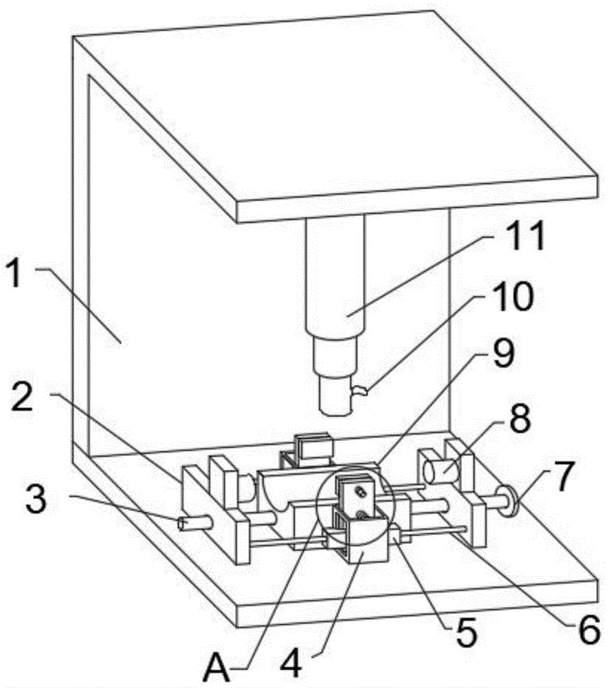
图1为本实用新型提出的一种三通沟槽管件气密性检测设备的正面结构示意图;Fig. 1 is the front structure schematic diagram of a kind of three-way grooved pipe fitting air tightness detection equipment proposed by the utility model;
图2为图1中A的局部放大图。FIG. 2 is a partial enlarged view of A in FIG. 1 .
图中:1安装腔、2竖板、3转轴、4固定腔、5斜块、6推杆、7转盘、8密封塞、9底座、10输气管、11电动伸缩杆、12夹块、13第一弹簧、14滑杆、15第二弹簧、16推板。In the picture: 1 installation cavity, 2 vertical plate, 3 rotating shaft, 4 fixed cavity, 5 inclined block, 6 push rod, 7 turntable, 8 sealing plug, 9 base, 10 gas pipeline, 11 electric telescopic rod, 12 clamping block, 13 First spring, 14 sliding rod, 15 second spring, 16 push plate.
具体实施方式Detailed ways
下面将结合本实用新型实施例中的附图,对本实用新型实施例中的技术方案进行清楚、完整地描述,显然,所描述的实施例仅仅是本实用新型一部分实施例,而不是全部的实施例。The technical solutions in the embodiments of the present utility model will be clearly and completely described below with reference to the accompanying drawings in the embodiments of the present utility model. Obviously, the described embodiments are only a part of the embodiments of the present utility model, rather than all the implementations. example.
本实用新型中所引用的如“上”、“下”、“左”、“右”、“中间”及“一”等的用语,亦仅为便于叙述的明了,而非用以限定本实用新型可实施的范围,其相对关系的改变或调整,在无实质变更技术内容下,当亦视为本实用新型可实施的范畴。Terms such as "up", "down", "left", "right", "middle" and "one" quoted in the present utility model are only for the convenience of description and clarity, and are not used to limit the present utility model. The applicable scope of the new model and the change or adjustment of its relative relationship shall be regarded as the applicable scope of the present invention without substantially changing the technical content.
参照图1-2,一种三通沟槽管件气密性检测设备,三通沟槽管件气密性检测设备包括:Referring to Figure 1-2, a three-way grooved pipe fittings air tightness testing equipment, the three-way grooved pipe fittings air tightness testing equipment includes:
安装腔1和安装腔1底侧壁上固定连接的底座9,底座9上表面呈曲面设置,底座9用于对三通管件的放置。The
密封部件,密封部件包括竖板2,转轴3、电动伸缩杆11,转轴3呈横向贯穿在底座9上,两个竖板2均滑动连接在安装腔1上,两个竖板2均呈凸字形设置,且位于底座9两侧,转轴3两端分别设有丝纹,转轴3两端的丝纹开口方向相对,使得在转轴3旋转时,螺纹连接在转轴3两端的竖板2居中移动,两个竖板2分别螺纹连接在转轴3两端,电动伸缩杆11固定连接在安装腔1上侧壁上,竖板2与电动伸缩杆11上均固定连接有密封塞8,密封部件用于对三通沟槽管件的密封,两个竖板2继续集中移动时,分别通过密封塞8对于位于底座9上的三通管件的两端开口进行密封,此时外界电源电性连接电动伸缩杆11,驱动电动伸缩杆11伸长并推动密封塞8向下移动,达到对三通管件另一个开口进行密封作用,密封塞8上固定连接有输气管10,输气管10连接外部的空气压缩设备,从而将气压通过输气管10进入三通管件内,进行气密性的检测,密封部件还包括转盘7,转盘7固定连接在转轴3的一端。Sealing component, the sealing component includes a
夹持部件包括固定腔4、推板16、夹块12,两个固定腔4均固定连接在安装腔1上,且位于底座9两侧,固定腔4两端分别滑动连接有斜块5,斜块5呈三角型设置,斜块5与竖板2之间固定连接有推杆6,两个推板16下端分别滑动连接在固定腔4内,推板16上滑动连接有滑杆14,两个夹块12分别固定连接在滑杆14上,两个夹块12上均设有防滑垫片,夹持部件还包括第一弹簧13、第二弹簧15,两个第一弹簧13分别固定连接在推板16与滑杆14之间,在两个推板16居中移动时,通过拉伸第一弹簧13,使得两个夹块12分别在第一弹簧的拉力下居中移动,从而达到对管件的夹持固定,两个第二弹簧15分别固定连接在固定腔4与推板16之间,在两个竖板2相互远离时,斜块5不再挤压推板16时,推板16便在第二弹簧5的拉力下进行复位移动。The clamping component includes a
本实用新型中,在对沟槽管件检测时,首先将管件放置在底座9上,通过转动转盘7并带动转轴3旋转,使得两个竖板2居中移动,在两个竖板2居中移动时,首先分别通过推杆6挤压斜块5居中移动,两个斜块5同时挤压推板16,并拉伸第二弹簧15,在两个推板16居中移动时通过滑杆14以及第一弹簧13挤压夹块12,使得两个夹块12达到对位于底座9上的三通沟槽管件具有夹持、固定的作用。In the present utility model, when detecting the grooved pipe fittings, the pipe fittings are firstly placed on the base 9, and the two
在夹块12对管件固定时,两个竖板2继续集中移动时,分别通过密封塞8对于位于底座9上的三通管件的两端开口进行密封,此时外界电源电性连接电动伸缩杆11,驱动电动伸缩杆11伸长并推动密封塞8向下移动,达到对三通管件另一个开口进行密封,此时将位于电动伸缩杆11上的密封带8上的输气管10连接外部的空气压缩设备,从而将气压通过输气管10进入三通管件内,进行气密性的检测。When the
在本实用新型中,除非另有明确的规定和限定,术语“安装”、“相连”、“连接”、“固定”等术语应做广义理解。In the present invention, unless otherwise expressly specified and limited, terms such as "installation", "connection", "connection", "fixing" and the like should be understood in a broad sense.
以上所述,仅为本实用新型较佳的具体实施方式,但本实用新型的保护范围并不局限于此,任何熟悉本技术领域的技术人员在本实用新型揭露的技术范围内,根据本实用新型的技术方案及其实用新型构思加以等同替换或改变,都应涵盖在本实用新型的保护范围之内。The above description is only a preferred embodiment of the present invention, but the protection scope of the present invention is not limited to this. Equivalent replacement or modification of the new technical solution and its utility model concept shall be included within the protection scope of the present utility model.
Claims (7)
Priority Applications (1)
| Application Number | Priority Date | Filing Date | Title |
|---|---|---|---|
| CN202123201429.1U CN216815856U (en) | 2021-12-20 | 2021-12-20 | Tee bend slot pipe fitting gas tightness check out test set |
Applications Claiming Priority (1)
| Application Number | Priority Date | Filing Date | Title |
|---|---|---|---|
| CN202123201429.1U CN216815856U (en) | 2021-12-20 | 2021-12-20 | Tee bend slot pipe fitting gas tightness check out test set |
Publications (1)
| Publication Number | Publication Date |
|---|---|
| CN216815856U true CN216815856U (en) | 2022-06-24 |
Family
ID=82053795
Family Applications (1)
| Application Number | Title | Priority Date | Filing Date |
|---|---|---|---|
| CN202123201429.1U Expired - Fee Related CN216815856U (en) | 2021-12-20 | 2021-12-20 | Tee bend slot pipe fitting gas tightness check out test set |
Country Status (1)
| Country | Link |
|---|---|
| CN (1) | CN216815856U (en) |
Cited By (2)
| Publication number | Priority date | Publication date | Assignee | Title |
|---|---|---|---|---|
| CN116164897A (en) * | 2023-04-21 | 2023-05-26 | 潍坊福泰机械有限公司 | Trench pipe fitting gas tightness check out test set |
| CN118362267A (en) * | 2024-06-20 | 2024-07-19 | 潍坊泰捷机械配件有限公司 | Groove pipe fitting air tightness detection equipment and detection method |
-
2021
- 2021-12-20 CN CN202123201429.1U patent/CN216815856U/en not_active Expired - Fee Related
Cited By (2)
| Publication number | Priority date | Publication date | Assignee | Title |
|---|---|---|---|---|
| CN116164897A (en) * | 2023-04-21 | 2023-05-26 | 潍坊福泰机械有限公司 | Trench pipe fitting gas tightness check out test set |
| CN118362267A (en) * | 2024-06-20 | 2024-07-19 | 潍坊泰捷机械配件有限公司 | Groove pipe fitting air tightness detection equipment and detection method |
Similar Documents
| Publication | Publication Date | Title |
|---|---|---|
| CN217765890U (en) | Pipeline mechanics test detection device | |
| CN211856111U (en) | A device for testing the hardness of PVC hoses | |
| CN205352837U (en) | A anchor clamps for detecting sealed tension and compression performance of gluing | |
| CN115078113B (en) | Pressure detection device for rubber sealing element production and use method | |
| CN109870277B (en) | Device for testing air tightness of water pump cavity | |
| CN110887624A (en) | Sealing detection system of leak detector with clamping and positioning functions | |
| CN208171544U (en) | A kind of seal for pipe joints vacuum checking device | |
| CN209542025U (en) | A kind of device for testing pump chamber air-tightness | |
| CN209811553U (en) | Sheet filling material laser welding fixture | |
| CN109211680B (en) | Valve welding end pressure test seal structure | |
| CN207649857U (en) | A kind of full-automatic four stations air tightness detection machine | |
| CN217878225U (en) | Test bench for detecting air tightness of valve parts | |
| CN215262304U (en) | Silane crosslinked polyethylene pipe airtightness testing device | |
| CN217561171U (en) | Electricity core deformation detection device | |
| CN217276656U (en) | High pressure hydrogen measurement is with hydrogen manometer that has joint seal structure | |
| CN209802609U (en) | A fixture for detecting three-phase power connection lines of electric vehicles | |
| CN207036370U (en) | A hydraulic test device for testing the welding and sealing performance of aluminum shell batteries | |
| CN212363143U (en) | Pipeline inspection tool and air tightness testing device thereof | |
| CN204988651U (en) | Graphite cake machine of leaking hunting | |
| CN205940905U (en) | Annotate liquid machine anchor clamps airtightness detecting device | |
| CN103759909A (en) | Device and method for detecting rubber shield air tightness | |
| CN213225811U (en) | Detection equipment for pipeline welding seam | |
| CN210293555U (en) | Quick-mounting air tightness test device | |
| CN202956250U (en) | Repair inspection device of polish rod sealer | |
| CN209727641U (en) | A kind of tubing internal pressure detection device |
Legal Events
| Date | Code | Title | Description |
|---|---|---|---|
| GR01 | Patent grant | ||
| GR01 | Patent grant | ||
| CF01 | Termination of patent right due to non-payment of annual fee |
Granted publication date: 20220624 |
|
| CF01 | Termination of patent right due to non-payment of annual fee |