CN216801880U - Steel cutting device - Google Patents
Steel cutting device Download PDFInfo
- Publication number
- CN216801880U CN216801880U CN202123280257.1U CN202123280257U CN216801880U CN 216801880 U CN216801880 U CN 216801880U CN 202123280257 U CN202123280257 U CN 202123280257U CN 216801880 U CN216801880 U CN 216801880U
- Authority
- CN
- China
- Prior art keywords
- fixedly connected
- block
- connecting frame
- steel
- cutting device
- Prior art date
- Legal status (The legal status is an assumption and is not a legal conclusion. Google has not performed a legal analysis and makes no representation as to the accuracy of the status listed.)
- Active
Links
- 229910000831 Steel Inorganic materials 0.000 title claims abstract description 45
- 239000010959 steel Substances 0.000 title claims abstract description 45
- 230000007246 mechanism Effects 0.000 claims abstract description 12
- 239000007787 solid Substances 0.000 claims description 14
- 230000002457 bidirectional effect Effects 0.000 claims description 9
- 239000000463 material Substances 0.000 claims description 4
- 238000000034 method Methods 0.000 abstract description 6
- 230000008569 process Effects 0.000 abstract description 5
- 230000009286 beneficial effect Effects 0.000 abstract 1
- 230000000694 effects Effects 0.000 description 2
- 230000004048 modification Effects 0.000 description 2
- 238000012986 modification Methods 0.000 description 2
- 230000008859 change Effects 0.000 description 1
- 230000008602 contraction Effects 0.000 description 1
- 238000010586 diagram Methods 0.000 description 1
Images


Landscapes
- Sawing (AREA)
Abstract
本实用新型公开了一种钢材切割装置,其技术方案是:包括连接架,连接架内部设有切割机构,切割机构延伸至连接架一侧;切割机构包括电机一,电机一固定连接在连接架一侧,一种钢材切割装置有益效果是:通过滚轴带动切割盘高速转动,随后根据钢材的高度与厚度,转动双向螺纹杆,带动两个螺纹块相向移动,横板通过与两个螺纹块、多个铰链和两个斜板相配合,使得横板向下移动,横板带动切割盘向下移动,对钢材进行切割,当钢材切通后,轴承座带动连接板左右往复移动,从而实现当需要对不同厚度钢材进行切割时,只需根据需要将切割盘的高度进行调节即可,操作过程方便,扩大了该装置切割的适用范围。
The utility model discloses a steel cutting device, the technical scheme of which is that it comprises a connecting frame, a cutting mechanism is arranged inside the connecting frame, and the cutting mechanism extends to one side of the connecting frame; the cutting mechanism comprises a motor one, and the first motor is fixedly connected to the connecting frame On one side, a steel cutting device has the beneficial effect of: driving the cutting disc to rotate at high speed through the roller, and then rotating the two-way threaded rod according to the height and thickness of the steel to drive the two threaded blocks to move toward each other, and the horizontal plate passes through the two threaded blocks. , Multiple hinges and two inclined plates cooperate to make the horizontal plate move downward, and the horizontal plate drives the cutting disc to move downward to cut the steel. When it is necessary to cut steel with different thicknesses, it is only necessary to adjust the height of the cutting disc according to the needs, the operation process is convenient, and the applicable range of the device for cutting is expanded.
Description
技术领域technical field
本实用新型涉及切割技术领域,具体涉及一种钢材切割装置。The utility model relates to the technical field of cutting, in particular to a steel cutting device.
背景技术Background technique
在现代工业行业中,钢材是一种广泛被使用的材料,然而刚购买的钢材有轻有重、有厚有薄难以进行加工,需要进行切割才能进一步加工。In the modern industrial industry, steel is a widely used material. However, the newly purchased steel is light or heavy, thick or thin, which is difficult to process and needs to be cut for further processing.
现有的切割装置都是靠转动切割盘对钢材进行切割,但切割盘结构单一,只能适用于一种规格厚度的钢材,不能针对不同规格厚度的钢材来调节切割盘的高度,使加工的速度大大降低,从而降低了该装置的实用性,有待改进。The existing cutting devices all use the rotating cutting disc to cut the steel, but the cutting disc has a single structure and can only be applied to the steel of one specification and thickness. The speed is greatly reduced, thereby reducing the usefulness of the device, which needs to be improved.
发明内容SUMMARY OF THE INVENTION
为此,本实用新型提供一种钢材切割装置,通过两个螺纹块相向移动,横板通过与两个螺纹块、多个铰链和两个斜板相配合,使得横板向下移动,横板带动切割盘向下移动,对钢材进行切割,以解决切割盘结构单一的问题。Therefore, the utility model provides a steel cutting device, through which two threaded blocks move toward each other, and the horizontal plate is matched with two threaded blocks, a plurality of hinges and two inclined plates, so that the horizontal plate moves downward, and the horizontal plate moves downward. Drive the cutting disc to move down to cut the steel, so as to solve the problem of the single structure of the cutting disc.
为了实现上述目的,本实用新型提供如下技术方案:一种钢材切割装置,包括连接架,所述连接架内部设有切割机构,所述切割机构延伸至连接架一侧;In order to achieve the above purpose, the present invention provides the following technical solutions: a steel cutting device, comprising a connecting frame, a cutting mechanism is arranged inside the connecting frame, and the cutting mechanism extends to one side of the connecting frame;
所述切割机构包括电机一,所述电机一固定连接在连接架一侧,所述电机一输出轴固定连接有往复丝杆,所述往复丝杆一端延伸至连接架另一侧内部,所述往复丝杆外侧套设有轴承座,所述轴承座与往复丝杆通过滚珠螺母副连接,所述轴承座底部固定连接有连接板,所述连接板底部固定连接有两个连接块,两个所述连接块内部嵌设有双向螺纹杆,所述双向螺纹杆外侧套设有固定块和两个螺纹块,两个所述螺纹块与双向螺纹杆均通过螺纹连接,两个所述螺纹块底部设有横板,所述横板与两个螺纹块内部均设有斜板,两个所述斜板与横板和两个螺纹块均通过铰链连接,所述横板底部固定连接有弹簧伸缩杆,所述弹簧伸缩杆底端固定连接有实心块,所述实心块后侧固定连接有电机二,所述电机二输出轴固定连接有滚轴,所述滚轴前端延伸至实心块前侧,所述滚轴外侧固定套接有切割盘。The cutting mechanism includes a motor 1, the motor 1 is fixedly connected to one side of the connecting frame, and the output shaft of the motor 1 is fixedly connected with a reciprocating screw rod, one end of the reciprocating screw rod extends to the inside of the other side of the connecting frame, the The outer side of the reciprocating screw rod is sleeved with a bearing seat, the bearing seat and the reciprocating screw rod are connected by a ball nut pair, the bottom of the bearing seat is fixedly connected with a connecting plate, and the bottom of the connecting plate is fixedly connected with two connecting blocks, two A two-way threaded rod is embedded inside the connecting block, a fixing block and two threaded blocks are sleeved on the outside of the two-way threaded rod, and the two threaded blocks are connected with the two-way threaded rod by threads. The bottom is provided with a horizontal plate, the horizontal plate and the two threaded blocks are both provided with inclined plates, the two inclined plates are connected with the horizontal plate and the two threaded blocks by hinges, and the bottom of the horizontal plate is fixedly connected with a spring A telescopic rod, the bottom end of the spring telescopic rod is fixedly connected with a solid block, the rear side of the solid block is fixedly connected with the second motor, the output shaft of the second motor is fixedly connected with a roller, and the front end of the roller extends to the front of the solid block A cutting disc is fixedly sleeved on the outer side of the roller.
优选的,所述固定块与横板内侧固定连接有伸缩杆,所述双向螺纹杆一端固定连接有方形块。Preferably, a telescopic rod is fixedly connected to the inner side of the fixed block and the horizontal plate, and a square block is fixedly connected to one end of the two-way threaded rod.
优选的,所述方形块外侧套设有套筒,所述套筒内部开设有限位槽,所述方形块外侧固定套接有限位块,所述限位块外侧延伸至限位槽内部,所述限位块与限位槽相匹配。Preferably, a sleeve is sleeved on the outer side of the square block, a limit groove is formed inside the sleeve, the limit block is fixedly sleeved on the outside of the square block, and the outside of the limit block extends to the inside of the limit groove, so The limit block is matched with the limit slot.
优选的,所述连接板一侧表面开设有圆孔,所述套筒外侧固定连接有多个插销,多个所述插销呈环形状均匀分布,其中一个所述插销延伸至圆孔内部,所述套筒一侧固定连接有把手。Preferably, a circular hole is formed on a surface of one side of the connecting plate, a plurality of pins are fixedly connected to the outer side of the sleeve, and the plurality of pins are evenly distributed in a ring shape, and one of the pins extends into the inside of the circular hole. A handle is fixedly connected to one side of the sleeve.
优选的,所述连接板底部表面开设有两个导向槽,两个所述螺纹块顶部分别延伸至两个导向槽内部,所述螺纹块与导向槽相匹配。Preferably, the bottom surface of the connecting plate is provided with two guide grooves, the tops of the two threaded blocks respectively extend into the interior of the two guide grooves, and the threaded blocks are matched with the guide grooves.
优选的,所述连接架顶部内侧开设有滑槽,所述轴承座顶部固定连接有滑块,所述滑块顶部延伸至滑槽内部,所述滑块与滑槽相匹配。Preferably, a chute is provided on the inner side of the top of the connecting frame, a slider is fixedly connected to the top of the bearing seat, the top of the slider extends to the inside of the chute, and the slider matches the chute.
优选的,所述连接架底部内侧开设有内腔,所述内腔内部设有连接杆,所述连接杆顶端延伸至连接架内部并固定连接有固定架,所述固定架内部设有钢材。Preferably, an inner cavity is opened on the inner side of the bottom of the connecting frame, a connecting rod is arranged inside the inner cavity, the top end of the connecting rod extends into the interior of the connecting frame and is fixedly connected with a fixing frame, and steel is provided inside the fixing frame.
优选的,所述连接杆外侧固定套接有蜗轮,所述蜗轮后侧设有蜗杆,所述蜗轮与蜗杆相啮合,所述蜗杆一端延伸至连接架一侧并固定连接有旋钮。Preferably, a worm wheel is fixedly sleeved on the outer side of the connecting rod, a worm screw is arranged on the rear side of the worm wheel, the worm wheel is engaged with the worm screw, and one end of the worm screw extends to one side of the connecting frame and is fixedly connected with a knob.
优选的,所述往复丝杆、连接杆和蜗杆与连接架连接处均通过轴承活动连接。Preferably, the reciprocating screw, the connecting rod and the worm are all movably connected with the connecting frame through bearings.
优选的,所述双向螺纹杆与固定块和两个连接块连接处通过轴承活动连接,所述滚轴与实心块连接处通过轴承活动连接。Preferably, the connection between the two-way threaded rod and the fixed block and the two connection blocks is movably connected through a bearing, and the connection between the roller and the solid block is movably connected through a bearing.
本实用新型实施例具有如下优点:The embodiments of the present utility model have the following advantages:
1、通过滚轴带动切割盘高速转动,随后根据钢材的高度与厚度,转动双向螺纹杆,带动两个螺纹块相向移动,横板通过与两个螺纹块、多个铰链和两个斜板相配合,使得横板向下移动,横板带动切割盘向下移动,对钢材进行切割,当钢材切通后,轴承座带动连接板左右往复移动,从而实现当需要对不同厚度钢材进行切割时,只需根据需要将切割盘的高度进行调节即可,操作过程方便,扩大了该装置切割的适用范围;1. Drive the cutting disc to rotate at high speed through the roller, and then rotate the two-way threaded rod according to the height and thickness of the steel to drive the two threaded blocks to move toward each other. When the steel is cut through, the bearing seat drives the connecting plate to reciprocate left and right, so that when it is necessary to cut steel with different thicknesses, only the The height of the cutting disc needs to be adjusted according to the needs, the operation process is convenient, and the applicable scope of the cutting device is expanded;
2、通过转动旋钮带动蜗杆转动,蜗杆通过与蜗轮相配合,使得蜗轮进行转动,蜗轮带动连接杆转动,连接杆带动固定架转动,固定架带动钢材转动,从而实现便于根据所要切割的角度,对钢材进行转动,该结构灵活性较好,操作简单,增加了实用性,进而提高装置的使用效率。2. Turn the knob to drive the worm to rotate, the worm cooperates with the worm wheel to make the worm wheel rotate, the worm wheel drives the connecting rod to rotate, the connecting rod drives the fixed frame to rotate, and the fixed frame drives the steel to rotate, so as to facilitate the cutting according to the angle to be cut. The steel is rotated, and the structure has good flexibility, simple operation, increased practicability, and improved use efficiency of the device.
附图说明Description of drawings
为了更清楚地说明本实用新型的实施方式或现有技术中的技术方案,下面将对实施方式或现有技术描述中所需要使用的附图作简单地介绍。显而易见地,下面描述中的附图仅仅是示例性的,对于本领域普通技术人员来讲,在不付出创造性劳动的前提下,还可以根据提供的附图引伸获得其它的实施附图。In order to more clearly illustrate the embodiments of the present invention or the technical solutions in the prior art, the following briefly introduces the accompanying drawings that are required to be used in the description of the embodiments or the prior art. Obviously, the drawings in the following description are only exemplary, and for those of ordinary skill in the art, other implementation drawings can also be obtained according to the extension of the drawings provided without creative efforts.
本说明书所绘示的结构、比例、大小等,均仅用以配合说明书所揭示的内容,以供熟悉此技术的人士了解与阅读,并非用以限定本实用新型可实施的限定条件,故不具技术上的实质意义,任何结构的修饰、比例关系的改变或大小的调整,在不影响本实用新型所能产生的功效及所能达成的目的下,均应仍落在本实用新型所揭示的技术内容得能涵盖的范围内。The structures, proportions, sizes, etc. shown in this specification are only used to cooperate with the contents disclosed in the specification, so as to be understood and read by those who are familiar with the technology, and are not used to limit the conditions that the present invention can be implemented. The technical substantive significance, the modification of any structure, the change of the proportional relationship or the adjustment of the size, without affecting the effect that the utility model can produce and the purpose that can be achieved, should still fall within the scope disclosed in the present utility model. The technical content must be within the scope of coverage.
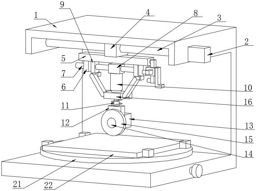
图1为本实用新型提供的整体结构示意图;Fig. 1 is the overall structure schematic diagram that the utility model provides;
图2为本实用新型提供的整体结构剖视图;Fig. 2 is the overall structure sectional view provided by the utility model;
图3为本实用新型提供的图2中A部结构放大图;Fig. 3 is an enlarged view of the structure of part A in Fig. 2 provided by the utility model;
图4为本实用新型提供的方形块、套筒和插销立体图。Figure 4 is a perspective view of a square block, a sleeve and a latch provided by the utility model.
图中:1连接架、2电机一、3往复丝杆、4轴承座、5连接板、6连接块、7双向螺纹杆、8固定块、9螺纹块、10横板、11弹簧伸缩杆、12实心块、13电机二、14滚轴、15切割盘、16伸缩杆、17方形块、18套筒、19插销、20连接杆、21固定架、22钢材、23蜗轮、24蜗杆。In the picture: 1 connecting frame, 2 motor one, 3 reciprocating screw rod, 4 bearing seat, 5 connecting plate, 6 connecting block, 7 two-way threaded rod, 8 fixed block, 9 threaded block, 10 horizontal plate, 11 spring telescopic rod, 12 solid blocks, 13 motor two, 14 rollers, 15 cutting discs, 16 telescopic rods, 17 square blocks, 18 sleeves, 19 bolts, 20 connecting rods, 21 fixing frames, 22 steel, 23 worm gears, 24 worms.
具体实施方式Detailed ways
以下由特定的具体实施例说明本实用新型的实施方式,熟悉此技术的人士可由本说明书所揭露的内容轻易地了解本实用新型的其他优点及功效,显然,所描述的实施例是本实用新型一部分实施例,而不是全部的实施例。基于本实用新型中的实施例,本领域普通技术人员在没有做出创造性劳动前提下所获得的所有其他实施例,都属于本实用新型保护的范围。The embodiments of the present invention will be described below by specific specific embodiments. Those who are familiar with the technology can easily understand other advantages and effects of the present invention from the contents disclosed in this specification. Obviously, the described embodiments are of the present invention. Some examples, but not all examples. Based on the embodiments of the present invention, all other embodiments obtained by those of ordinary skill in the art without creative work fall within the protection scope of the present invention.
参照附图1-4,本实用新型提供的一种钢材切割装置,包括连接架1,连接架1内部设有切割机构,切割机构延伸至连接架1一侧;1-4, a steel cutting device provided by the present invention includes a connecting frame 1, and a cutting mechanism is arranged inside the connecting frame 1, and the cutting mechanism extends to one side of the connecting frame 1;
切割机构包括电机一2,电机一2固定连接在连接架1一侧,电机一2输出轴固定连接有往复丝杆3,往复丝杆3一端延伸至连接架1另一侧内部,往复丝杆3外侧套设有轴承座4,轴承座4与往复丝杆3通过滚珠螺母副连接,轴承座4底部固定连接有连接板5,连接板5底部固定连接有两个连接块6,两个连接块6内部嵌设有双向螺纹杆7,双向螺纹杆7外侧套设有固定块8和两个螺纹块9,两个螺纹块9与双向螺纹杆7均通过螺纹连接,两个螺纹块9底部设有横板10,横板10与两个螺纹块9内部均设有斜板,两个斜板与横板10和两个螺纹块9均通过铰链连接,横板10底部固定连接有弹簧伸缩杆11,弹簧伸缩杆11底端固定连接有实心块12,实心块12后侧固定连接有电机二13,电机二13输出轴固定连接有滚轴14,滚轴14前端延伸至实心块12前侧,滚轴14外侧固定套接有切割盘15;The cutting mechanism includes a motor one 2, the motor one 2 is fixedly connected to one side of the connecting frame 1, the output shaft of the motor one 2 is fixedly connected with a
本实施方案中,接通电源,电机二13带动滚轴14转动,滚轴14带动切割盘15高速转动,随后根据钢材22的高度与厚度,转动双向螺纹杆7,因双向螺纹杆7外侧两段螺纹方向相反,使得双向螺纹杆7转动时带动两个螺纹块9相向移动,同时两个螺纹块9只能沿着两个导向槽做直线移动,使得两个螺纹块9不会跟随双向螺纹杆7一同转动,横板10通过与两个螺纹块9、多个铰链和两个斜板相配合,使得横板10向下移动,横板10带动弹簧伸缩杆11、实心块12和切割盘15向下移动,对钢材22进行切割,当钢材22切通后,再启动电机一2,电机一2带动往复丝杆3转动,往复丝杆3通过与轴承座4相配合,使得轴承座4带动连接板5左右往复移动,从而实现当需要对不同厚度钢材22进行切割时,只需根据需要将切割盘15的高度进行调节即可,操作过程方便,扩大了该装置切割的适用范围。In this embodiment, when the power is turned on, the
其中,为了实现固定的目的,本装置采用如下技术方案实现的:固定块8与横板10内侧固定连接有伸缩杆16,双向螺纹杆7一端固定连接有方形块17,方形块17外侧套设有套筒18,套筒18内部开设有限位槽,方形块17外侧固定套接有限位块,限位块外侧延伸至限位槽内部,限位块与限位槽相匹配,连接板5一侧表面开设有圆孔,套筒18外侧固定连接有多个插销19,多个插销19呈环形状均匀分布,其中一个插销19延伸至圆孔内部,套筒18一侧固定连接有把手,握住把手向右移动,带动套筒18和多个插销19向右移动,当插销19远离圆孔内部时,转动把手带动套筒18转动,套筒18带动方形块17转动,方形块17与其他结构相配合,完成对切割盘15的高度调节,当调节到合适位置后,握住把手向左移动,带动套筒18和插销19向左移动,插销19进入运漕内部后,即可对套筒18固定,从而实现避免切割盘15在进行切割时,位置发生移动;Among them, in order to achieve the purpose of fixing, the device adopts the following technical solutions: a
其中,为了实现转动的目的,本装置采用如下技术方案实现的:连接架1底部内侧开设有内腔,内腔内部设有连接杆20,连接杆20顶端延伸至连接架1内部并固定连接有固定架21,固定架21内部设有钢材22,连接杆20外侧固定套接有蜗轮23,蜗轮23后侧设有蜗杆24,蜗轮23与蜗杆24相啮合,蜗杆24一端延伸至连接架1一侧并固定连接有旋钮,当需要对钢材22进行不同角度地切割时,转动旋钮带动蜗杆24转动,蜗杆24通过与蜗轮23相配合,使得蜗轮23进行转动,蜗轮23带动连接杆20转动,连接杆20带动固定架21转动,固定架21带动钢材22转动,从而实现便于根据所要切割的角度,对钢材22进行转动,该结构灵活性较好,操作简单,增加了实用性,进而提高装置的使用效率。Wherein, in order to achieve the purpose of rotation, the device adopts the following technical solutions: an inner cavity is opened on the inner side of the bottom of the connecting frame 1, a connecting
本实用新型的使用过程如下:在使用本实用新型时,工作人员接通电源后,电机二13带动滚轴14转动,滚轴14带动切割盘15高速转动,随后根据钢材22的高度与厚度,握住把手向右移动,带动套筒18和多个插销19向右移动,当插销19远离圆孔内部时,转动把手带动套筒18转动,套筒18带动方形块17转动,方形块17带动双向螺纹杆7转动,因双向螺纹杆7外侧两段螺纹方向相反,使得双向螺纹杆7转动时带动两个螺纹块9相向移动,同时两个螺纹块9只能沿着两个导向槽做直线移动,使得两个螺纹块9不会跟随双向螺纹杆7一同转动,横板10通过与两个螺纹块9、多个铰链和两个斜板相配合,使得横板10向下移动,横板10带动弹簧伸缩杆11、实心块12和切割盘15向下移动,对钢材22进行切割,当钢材22切通后,再启动电机一2,电机一2带动往复丝杆3转动,往复丝杆3通过与轴承座4相配合,使得轴承座4带动连接板5左右往复移动,从而实现当需要对不同厚度钢材22进行切割时,只需根据需要将切割盘15的高度进行调节即可。The use process of the present utility model is as follows: when the utility model is used, after the worker turns on the power supply, the
以上所述,仅是本实用新型的较佳实施例,任何熟悉本领域的技术人员均可能利用上述阐述的技术方案对本实用新型加以修改或将其修改为等同的技术方案。因此,依据本实用新型的技术方案所进行的任何简单修改或等同置换,尽属于本实用新型要求保护的范围。The above are only preferred embodiments of the present invention, and any person skilled in the art may modify the present invention by using the technical solutions described above or modify them into equivalent technical solutions. Therefore, any simple modification or equivalent replacement performed according to the technical solution of the present invention falls within the protection scope of the present invention.
Claims (10)
Priority Applications (1)
| Application Number | Priority Date | Filing Date | Title |
|---|---|---|---|
| CN202123280257.1U CN216801880U (en) | 2021-12-24 | 2021-12-24 | Steel cutting device |
Applications Claiming Priority (1)
| Application Number | Priority Date | Filing Date | Title |
|---|---|---|---|
| CN202123280257.1U CN216801880U (en) | 2021-12-24 | 2021-12-24 | Steel cutting device |
Publications (1)
| Publication Number | Publication Date |
|---|---|
| CN216801880U true CN216801880U (en) | 2022-06-24 |
Family
ID=82055383
Family Applications (1)
| Application Number | Title | Priority Date | Filing Date |
|---|---|---|---|
| CN202123280257.1U Active CN216801880U (en) | 2021-12-24 | 2021-12-24 | Steel cutting device |
Country Status (1)
| Country | Link |
|---|---|
| CN (1) | CN216801880U (en) |
-
2021
- 2021-12-24 CN CN202123280257.1U patent/CN216801880U/en active Active
Similar Documents
| Publication | Publication Date | Title |
|---|---|---|
| CN221436054U (en) | A pipe opening grinding device for pipe processing | |
| CN219837473U (en) | Multi-angle four-axis processing frock | |
| CN221676023U (en) | A nut inner hole thread processing device | |
| CN206780209U (en) | A kind of hand-rail type clamping device | |
| CN210677941U (en) | Turning device precision finishing structure | |
| CN109277608B (en) | Double-milling-head machining device | |
| CN217122387U (en) | Turning and milling combined machine tool capable of adjusting position of cutter | |
| CN212145487U (en) | Positioning tool for machining motor shell | |
| CN219464970U (en) | Angle-adjustable device for conical gear production | |
| CN219005316U (en) | A support height adjustment mechanism for mechanical processing | |
| CN208433832U (en) | It is a kind of can the fixed stepper motor of multi-angle | |
| CN219521702U (en) | An automatic steel pipe polishing machine | |
| CN212398863U (en) | Anchor clamps for machining convenient to adjust | |
| CN211728785U (en) | Piston rod polishes and uses fixing device | |
| CN217776225U (en) | Swinging transmission mechanism for machining and assembling of five-axis linkage numerical control machine tool | |
| CN211332638U (en) | A high-efficiency spindle mechanism | |
| CN221833822U (en) | Workpiece clamping device for machine manufacturing | |
| CN218396801U (en) | Rolling spline tool for machining motor shaft | |
| CN222327328U (en) | Milling surface processing device for high-purity aluminum plate | |
| CN218965574U (en) | Adjusting structure of splitting machine | |
| CN221910771U (en) | A CNC rotary fixture | |
| CN222405235U (en) | A clamp for machining sector gears | |
| CN218192960U (en) | Multifunctional gear grinding machining device for agricultural machinery gear | |
| CN224002323U (en) | Adjustable non-90 aluminum template | |
| CN221110065U (en) | Metal processing equipment convenient to installation |
Legal Events
| Date | Code | Title | Description |
|---|---|---|---|
| GR01 | Patent grant | ||
| GR01 | Patent grant |