CN216785779U - Detachable cavitation device of multi-structure combination - Google Patents
Detachable cavitation device of multi-structure combination Download PDFInfo
- Publication number
- CN216785779U CN216785779U CN202122792674.8U CN202122792674U CN216785779U CN 216785779 U CN216785779 U CN 216785779U CN 202122792674 U CN202122792674 U CN 202122792674U CN 216785779 U CN216785779 U CN 216785779U
- Authority
- CN
- China
- Prior art keywords
- cavitation
- orifice plate
- triangular
- venturi tube
- venturi
- Prior art date
- Legal status (The legal status is an assumption and is not a legal conclusion. Google has not performed a legal analysis and makes no representation as to the accuracy of the status listed.)
- Expired - Fee Related
Links
- XLYOFNOQVPJJNP-UHFFFAOYSA-N water Substances O XLYOFNOQVPJJNP-UHFFFAOYSA-N 0.000 claims abstract description 15
- 230000008602 contraction Effects 0.000 claims 1
- 239000012530 fluid Substances 0.000 abstract description 5
- 238000007789 sealing Methods 0.000 abstract description 4
- 239000007788 liquid Substances 0.000 description 9
- 238000000034 method Methods 0.000 description 6
- 230000000694 effects Effects 0.000 description 5
- 239000007789 gas Substances 0.000 description 2
- 239000002184 metal Substances 0.000 description 2
- 229920006395 saturated elastomer Polymers 0.000 description 2
- UFHFLCQGNIYNRP-UHFFFAOYSA-N Hydrogen Chemical compound [H][H] UFHFLCQGNIYNRP-UHFFFAOYSA-N 0.000 description 1
- QVGXLLKOCUKJST-UHFFFAOYSA-N atomic oxygen Chemical compound [O] QVGXLLKOCUKJST-UHFFFAOYSA-N 0.000 description 1
- 230000009286 beneficial effect Effects 0.000 description 1
- 230000005540 biological transmission Effects 0.000 description 1
- 239000001257 hydrogen Substances 0.000 description 1
- 229910052739 hydrogen Inorganic materials 0.000 description 1
- 125000004435 hydrogen atom Chemical group [H]* 0.000 description 1
- 125000002887 hydroxy group Chemical group [H]O* 0.000 description 1
- 239000001301 oxygen Substances 0.000 description 1
- 229910052760 oxygen Inorganic materials 0.000 description 1
- 239000002245 particle Substances 0.000 description 1
- 238000000926 separation method Methods 0.000 description 1
- 230000035939 shock Effects 0.000 description 1
- 210000003934 vacuole Anatomy 0.000 description 1
Images




Landscapes
- Details Of Valves (AREA)
Abstract
Description
技术领域technical field
本实用新型设计了一种在流体流动过程中产生流体动力空化的装置,属于流体动力空化领域。The utility model designs a device for generating hydrodynamic cavitation in a fluid flow process, which belongs to the field of hydrodynamic cavitation.
背景技术Background technique
流体空化是当液体中某处的局部压力低于该处饱和蒸汽压力(气液分离压力)时,在液体中会有许多气体空穴产生,这些空穴(空泡)随液体流动到高压区内,在高压区的压力梯度下收缩、溃灭的整个过程就称为空化。Fluid cavitation is that when the partial pressure in a liquid is lower than the saturated vapor pressure (gas-liquid separation pressure), many gas cavities will be generated in the liquid, and these cavities (cavities) will flow with the liquid to high pressure. The whole process of shrinking and collapsing under the pressure gradient of the high pressure region is called cavitation.
据研究表明,空化会在局部产生5000K以上的高温和50MPa左右的高压,并伴有强烈的冲击波和时速达400km/h的射流,这股空化的能量,会打开水分子间的氢氧键,使水分解为羟基和氢基,而且会使液体中产生一些其它的自由基,以及一定量新的带电粒子。According to research, cavitation will locally generate a high temperature above 5000K and a high pressure of about 50MPa, accompanied by a strong shock wave and a jet with a speed of 400km/h. This cavitation energy will open the hydrogen and oxygen between the water molecules. bond, which splits water into hydroxyl and hydrogen groups, and generates some other free radicals in the liquid, as well as a certain amount of new charged particles.
实用新型内容Utility model content
本发明提出了一种多结构组合可拆卸式空化装置,他是由入水口管端(1)、管道与孔板螺纹连接处(2)、可拆卸单圆形孔板(14)、单孔板与二级并联空腔型文丘里管螺纹连接处(4)、二级并联空腔型文丘里管(13)、文丘里管与可拆卸三角形五孔孔板螺纹连接处(9)、可拆卸三角形五孔孔板(12)以及出水口管道(11)组成。本发明可以进行多级串联空化,但由于空化管道过长会导致能量损失严重固以三级串联空化为代表。The invention provides a multi-structure combined detachable cavitation device, which is composed of a water inlet pipe end (1), a threaded connection between a pipe and an orifice plate (2), a detachable single circular orifice plate (14), a single The threaded connection between the orifice plate and the secondary parallel cavity type Venturi tube (4), the secondary parallel cavity type Venturi tube (13), the threaded connection between the Venturi tube and the detachable triangular five-hole orifice plate (9), It is composed of a detachable triangular five-hole orifice plate (12) and a water outlet pipe (11). The present invention can carry out multi-stage series cavitation, but because the cavitation pipeline is too long, it will lead to serious energy loss, which is represented by three-stage series cavitation.
该结构特征在于,这是一个可以发生三级空化的串联整体式结构,且二级并联空腔型文丘里管(13)与三角形五孔孔板(12)可以发生并联空化效果,可以有效的弥补空化不充分现象;在入水口管段端(1)设有变量泵与结构配合使用保证入水口出压力稳定。在并联文丘里管处(13)设有两个文丘里管口(5),来把大股的水流分散成小股,在喉部处进行二级空化。尾部文丘里管扩散段(8)使水流更加全面的接触到三角形五孔孔板(12),发生三级空化。The structure is characterized in that it is a series integral structure capable of tertiary cavitation, and the parallel cavitation effect can occur between the two-stage parallel cavity-type venturi tube (13) and the triangular five-hole orifice plate (12), which can Effectively compensate for insufficient cavitation; at the end of the pipe section of the water inlet (1), a variable pump is arranged in conjunction with the structure to ensure the stability of the outlet pressure of the water inlet. Two venturi nozzles (5) are arranged at the parallel venturi tube (13) to disperse the large stream of water into small streams, and perform secondary cavitation at the throat. The diffuser section (8) of the tail venturi tube makes the water flow more comprehensively contact with the triangular five-hole orifice plate (12), and tertiary cavitation occurs.
作为优选:入水口管道(1)与单圆孔孔板(14),单圆孔孔板(14)和三角形五孔孔板(12)与二级并联空腔型文丘里管(13)以及三角形五孔孔板(12)与出水口管道连接时采用梯形螺纹进行连接(梯形螺纹传动效果好便于拆卸)内部连接时采用垫片来增加密封性。As a preference: the water inlet pipe (1) and the single circular hole orifice plate (14), the single circular hole orifice plate (14) and the triangular five-hole orifice plate (12) and the secondary parallel cavity type Venturi tube (13) and When the triangular five-hole orifice plate (12) is connected with the water outlet pipe, the trapezoidal thread is used for connection (the trapezoidal thread has a good transmission effect and is easy to disassemble). When the internal connection is made, a gasket is used to increase the tightness.
作为优选:单圆形孔板(14)、二级并联空腔型文丘里管(13)与三角形五孔孔板(12)采用一体式圆柱体金属棒材直接进行加工,既避免了组合式加工带来的密封性差的问题又可以通过孔与轴连接的直径同一选取金属棒材进行加工。As a preference, the single circular orifice plate (14), the two-stage parallel cavity type Venturi tube (13) and the triangular five-hole orifice plate (12) are directly processed with an integrated cylindrical metal bar, which not only avoids the need for a combined type The problem of poor sealing caused by processing can also be processed by selecting a metal bar with the same diameter of the connection between the hole and the shaft.
作为优选:一级空化发生出处主要采用单个孔板(14)来达到最大压降来增强空化效果,二级空化采用圆形并联型文丘里管增大发生空化的面积(13)。三级空化采用五孔三角形孔板(12)通过增加流道内结构尺寸突变来增加发生空化的效果,避免空化发生的不全面。As a preference: a single orifice plate (14) is mainly used at the source of the primary cavitation to achieve the maximum pressure drop to enhance the cavitation effect, and a circular parallel Venturi tube is used for the secondary cavitation to increase the area where cavitation occurs (13) . The three-stage cavitation adopts the five-hole triangular orifice plate (12) to increase the effect of cavitation by increasing the sudden change of the structure size in the flow channel, so as to avoid the incomplete occurrence of cavitation.
作为优选:本发明结构上包含了多种可变性,孔板与文丘里管的组合从孔板的孔型、孔数到孔的排布以及文丘里管的并联级数和形状拥有不下二十多种组合形式。在应用过程中可以随工作环境和空化介质的不同进行空化组合的变化。As a preference: the structure of the present invention includes a variety of variability, the combination of the orifice plate and the venturi tube has no less than twenty from the hole type of the orifice plate, the number of holes to the arrangement of the holes, and the parallel series and shape of the venturi tube. Various combinations. During the application process, the cavitation combination can be changed according to the working environment and the cavitation medium.
本发明的有益效果有:The beneficial effects of the present invention are:
本发明采用的是三级空化结构,在三级空化的每个部分进行了空化流道的变形状化来增加空化过程中空泡的产生面积。通过一级一级的空化,可以有效地防止空化的不充分,从而有效地提高空化的效率。The present invention adopts a three-stage cavitation structure, and the cavitation flow channel is deformed in each part of the three-stage cavitation to increase the generation area of cavitation in the cavitation process. Through the cavitation step by step, the insufficiency of cavitation can be effectively prevented, thereby effectively improving the efficiency of cavitation.
两段孔板之间由加工的内螺纹进行连接,整体加长了内螺纹的长度来提高螺纹旋合的长度来提高空化装置的密封性,防止压力的损失。The two orifice plates are connected by the machined internal thread, and the length of the internal thread is lengthened as a whole to increase the length of the thread to improve the sealing performance of the cavitation device and prevent the loss of pressure.
在二级空化处,文丘里管部分采用的是锥形结构加长了喉部直径,提高了粗糙度加强了空化效率;In the secondary cavitation, the conical structure of the venturi tube is used to lengthen the throat diameter, improve the roughness and strengthen the cavitation efficiency;
该发明的设计结构是一种便拆卸组合式空化设计,包含了多种可变性。因此可以适用于多种空化环境要求。The design structure of the invention is an easily disassembled combined cavitation design, which includes a variety of variability. Therefore, it can be applied to a variety of cavitation environment requirements.
附图说明Description of drawings
附图1,本发明的装配结构剖视图。Figure 1 is a cross-sectional view of the assembly structure of the present invention.
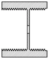
附图2,单圆孔孔板左剖视图Accompanying
附图3,内孔式并联文丘里管左剖视图Accompanying
附图4,三角形五孔孔板左剖视图Accompanying drawing 4, the left sectional view of triangular five-hole orifice plate
附图5,单圆孔孔板主剖视图Accompanying drawing 5, single round hole orifice main sectional view
附图6,内孔式并联文丘里管主剖视图Accompanying
附图7,三角形五孔孔板主剖视图Accompanying drawing 7, the main sectional view of triangular five-hole orifice plate
图中:入水口管端(1)、管道与孔板螺纹连接处(2)、圆形孔板口(3)、单孔板与二级并联空腔型文丘里管螺纹连接处(4)、文丘里管收缩段(5)、文丘里管喉部(6)、并联内孔式文丘里管(7、13)、文丘里管扩张段(8)、并联文丘里管与孔三角形孔板螺纹连接处(9)、三角形孔板(10)、三角形孔板与出口管道螺纹连接处(11)、三角形五孔孔板(12)、单圆形孔板(14)。In the picture: the pipe end of the water inlet (1), the threaded connection between the pipe and the orifice plate (2), the mouth of the circular orifice plate (3), the threaded connection between the single orifice plate and the secondary parallel cavity type Venturi pipe (4) , Venturi constriction section (5), Venturi throat (6), parallel inner hole Venturi (7, 13), Venturi expansion section (8), parallel Venturi and hole triangular orifice A threaded connection (9), a triangular orifice plate (10), a threaded connection between the triangular orifice plate and the outlet pipe (11), a triangular five-hole orifice plate (12), and a single circular orifice plate (14).
具体实施方式:Detailed ways:
以下结合附图进一步说明本发明的具体结构及实施方式。The specific structure and embodiments of the present invention are further described below with reference to the accompanying drawings.
结合图1至图7,本发明的结构组成包括:入水口管端(1)、管道与孔板螺纹连接处(2)、圆形孔板口(3)、单孔板与二级并联空腔型文丘里管螺纹连接处(4)、文丘里管收缩段(5)、文丘里管喉部(6)、并联内孔式文丘里管(7、13)、文丘里管扩张段(8)、并联文丘里管与孔三角形孔板螺纹连接处(9)、三角形孔板(10)、三角形孔板与出口管道螺纹连接处(11)、三角形五孔孔板(12)、单圆形孔板(14)。1 to 7 , the structure of the present invention includes: the water inlet pipe end (1), the threaded connection between the pipe and the orifice plate (2), the circular orifice plate mouth (3), the single-orifice plate and the secondary parallel air Cavity Venturi threaded connection (4), Venturi constriction section (5), Venturi throat (6), parallel bore Venturi (7, 13), Venturi expansion section (8) ), the threaded connection between the parallel Venturi tube and the triangular orifice plate (9), the triangular orifice plate (10), the threaded connection between the triangular orifice plate and the outlet pipe (11), the triangular five-hole orifice plate (12), the single circular orifice plate (14).
本发明结构中单圆形孔板(14)、并联内孔式文丘里管(7、13)和三角形五孔孔板(12)之间采用梯形螺纹进行连接。增加了两部分孔板的厚度,提高了其耐磨损性。采用并联内孔式文丘里管来提高空化面积。所有零件采用一体式加工工艺,提高了装置的密封性和加工简便性。In the structure of the present invention, trapezoidal threads are used for connection between the single circular orifice plate (14), the parallel inner hole type Venturi tubes (7, 13) and the triangular five-hole orifice plate (12). The thickness of the two-part orifice plate has been increased to improve its wear resistance. The cavitation area is increased by using parallel bore venturi tubes. All parts are processed in one piece, which improves the sealing of the device and the simplicity of processing.
本发明的工作过程如下:The working process of the present invention is as follows:
当流体流经圆形孔板口(3)处时发生了第一级空化,选取单孔来提高压降效果,一级空化的空泡生长周期较短。随后流体流经文丘里管收缩段(5)时压力再次开始降低到文丘里管喉部(6)处这段流道时间内,由于压力不断降低,直到低于饱和蒸气压后,液体内部溶解的气体以及部分汽化的液体从液体中析出。从而文丘里管内壁面有空泡的产生、生长以及溃灭,发生了二级空化。随后流经文丘里管扩张段(8)到达三角形孔板(10),此处由于孔板形状突变又是多孔排布流道内发生空化会更加充分。When the fluid flows through the circular orifice orifice (3), the first-stage cavitation occurs, and a single hole is selected to improve the pressure drop effect, and the growth period of the first-stage cavitation is short. Then, when the fluid flows through the constricted section (5) of the venturi tube, the pressure begins to decrease again to the throat of the venturi tube (6) during this period of time, due to the continuous decrease of the pressure, the liquid dissolves inside the liquid until it is lower than the saturated vapor pressure. The gas and partially vaporized liquid are precipitated from the liquid. As a result, the inner wall of the Venturi tube has the generation, growth and collapse of vacuoles, and secondary cavitation occurs. Then flow through the venturi expansion section (8) to reach the triangular orifice plate (10), where cavitation will be more sufficient due to the sudden change in the shape of the orifice plate and the porous arrangement of the flow channel.
以上显示和描述了本发明的基本原理和主要特征。本发明不受上述实施例的限制,上述实施例和说明书描述的只是发明的原理,在不脱离本发明的精神和范围的前提下,本发明还会有各种变化和改进,这些改进都属于要求保护的本发明范围内。The basic principles and main features of the present invention have been shown and described above. The present invention is not limited by the above-mentioned embodiments. The above-mentioned embodiments and descriptions only describe the principles of the invention. Without departing from the spirit and scope of the present invention, the present invention will also have various changes and improvements. These improvements belong to within the scope of the claimed invention.
Claims (3)
Priority Applications (1)
| Application Number | Priority Date | Filing Date | Title |
|---|---|---|---|
| CN202122792674.8U CN216785779U (en) | 2021-11-16 | 2021-11-16 | Detachable cavitation device of multi-structure combination |
Applications Claiming Priority (1)
| Application Number | Priority Date | Filing Date | Title |
|---|---|---|---|
| CN202122792674.8U CN216785779U (en) | 2021-11-16 | 2021-11-16 | Detachable cavitation device of multi-structure combination |
Publications (1)
| Publication Number | Publication Date |
|---|---|
| CN216785779U true CN216785779U (en) | 2022-06-21 |
Family
ID=82002943
Family Applications (1)
| Application Number | Title | Priority Date | Filing Date |
|---|---|---|---|
| CN202122792674.8U Expired - Fee Related CN216785779U (en) | 2021-11-16 | 2021-11-16 | Detachable cavitation device of multi-structure combination |
Country Status (1)
| Country | Link |
|---|---|
| CN (1) | CN216785779U (en) |
Cited By (5)
| Publication number | Priority date | Publication date | Assignee | Title |
|---|---|---|---|---|
| CN115215521A (en) * | 2022-08-01 | 2022-10-21 | 陕西航天德林科技集团有限公司 | Oil sludge treatment process and equipment |
| CN116422264A (en) * | 2023-05-11 | 2023-07-14 | 迈安德集团有限公司 | Multi-combination easy-to-control cavitation generator |
| CN118878098A (en) * | 2024-07-16 | 2024-11-01 | 中北大学 | A hydraulic cavitation combined with electromagnetic descaling device and method |
| CN120513736A (en) * | 2025-04-25 | 2025-08-22 | 哈尔滨工程大学 | A large-scale water pool air nucleus seeding system under negative pressure environment |
| CN120551258A (en) * | 2025-07-30 | 2025-08-29 | 太原理工大学 | High-pressure controllable cavitation jet forming device and method for manufacturing thin-strip microstructures |
-
2021
- 2021-11-16 CN CN202122792674.8U patent/CN216785779U/en not_active Expired - Fee Related
Cited By (5)
| Publication number | Priority date | Publication date | Assignee | Title |
|---|---|---|---|---|
| CN115215521A (en) * | 2022-08-01 | 2022-10-21 | 陕西航天德林科技集团有限公司 | Oil sludge treatment process and equipment |
| CN116422264A (en) * | 2023-05-11 | 2023-07-14 | 迈安德集团有限公司 | Multi-combination easy-to-control cavitation generator |
| CN118878098A (en) * | 2024-07-16 | 2024-11-01 | 中北大学 | A hydraulic cavitation combined with electromagnetic descaling device and method |
| CN120513736A (en) * | 2025-04-25 | 2025-08-22 | 哈尔滨工程大学 | A large-scale water pool air nucleus seeding system under negative pressure environment |
| CN120551258A (en) * | 2025-07-30 | 2025-08-29 | 太原理工大学 | High-pressure controllable cavitation jet forming device and method for manufacturing thin-strip microstructures |
Similar Documents
| Publication | Publication Date | Title |
|---|---|---|
| CN104675760B (en) | A kind of nozzle-adjustable steam ejector | |
| CN102588353B (en) | Self excited oscillation type jet vacuum pump | |
| CN104772241B (en) | Ejector with convergent-divergent nozzle type receiving chamber | |
| CN201949953U (en) | High-efficiency energy-saving nozzle and steam injection pump with nozzle | |
| CN106861961A (en) | A kind of self-adjustable injector | |
| CN101936309A (en) | Two-phase flow jet-type boosting heat exchanger | |
| CN107930548A (en) | A kind of cavitation generator of achievable two-stage cavitation | |
| CN106064122A (en) | Sawtooth injecting type evacuation | |
| CN104772239A (en) | Supersonic speed chrysanthemum-shaped nozzle and gas jet vacuum pump provided with same | |
| CN109956520A (en) | A two-stage cavitation generator with a composite structure | |
| CN104828884A (en) | Multilayer nested cavitator capable of forming large-range cavitation | |
| CN204512014U (en) | A kind of nozzle-adjustable steam ejector | |
| CN112047425A (en) | Three-stage hydrodynamic cavitation device | |
| CN101798518B (en) | Top gas confluence method and device of atmospheric and vacuum distillation tower | |
| CN219879579U (en) | Microbubble generating device | |
| CN207192866U (en) | A kind of tandem Venturi tube cavitation apparatus | |
| CN119288728B (en) | A device for preventing backflow aeration and reducing cavitation | |
| CN207981121U (en) | A kind of cavitation generator of achievable two-stage cavitation | |
| CN210919593U (en) | Jet pump capable of automatically and uniformly supplementing air and reducing corrosion | |
| CN205654618U (en) | Steam -jet ejector water pump | |
| CN112627780B (en) | an ejector | |
| CN219730612U (en) | Cavitation generator with conical multistage annular gap | |
| CN110685964A (en) | A Jet Pump for Automatic and Uniform Air Supplementation and Corrosion Reduction | |
| CN216395931U (en) | Novel ejector | |
| RU106924U1 (en) | LIQUID-JET COMPRESSOR |
Legal Events
| Date | Code | Title | Description |
|---|---|---|---|
| GR01 | Patent grant | ||
| GR01 | Patent grant | ||
| CF01 | Termination of patent right due to non-payment of annual fee |
Granted publication date: 20220621 |
|
| CF01 | Termination of patent right due to non-payment of annual fee |