SUMMERY OF THE UTILITY MODEL
The utility model aims to provide a feeding shell, a sowing system and unmanned equipment, which can improve the synchronism of material sowing so as to improve the sowing effect.
The embodiment of the utility model is realized by the following steps:
in a first aspect, an embodiment of the present invention provides a feeding housing, including a housing body, where the housing body is provided with a feeding port and an accommodating cavity;
the feed inlet is used for being arranged corresponding to the discharge hole of the storage container;
the number of the accommodating cavities comprises two, the two accommodating cavities are both communicated with the feed inlet, and the two accommodating cavities are both used for installing conveying assemblies capable of conveying materials;
the shell body is integrally formed.
Further, in an alternative embodiment, the feed housing further comprises a partition;
the partition part is arranged in the shell body and divides the inner cavity of the shell body into two containing cavities.
Further, in an alternative embodiment, the housing body includes a first side wall, a second side wall, a first end wall, and a second end wall;
the first side wall and the second side wall are oppositely arranged, one end of the first side wall is connected with one end of the second side wall through the first end wall, and the other end of the first side wall is connected with the other end of the second side wall through the second end wall;
the two ends of the partition part are respectively connected with the first side wall and the second side wall, the partition part comprises a first guide surface and a second guide surface which are arranged in a back-to-back mode, one of the accommodating cavities is formed by the first side wall, the first end wall, the second side wall and the first guide surface in a surrounding mode, and the other accommodating cavity is formed by the first side wall, the second end wall, the second side wall and the second guide surface in a surrounding mode.
Further, in an alternative embodiment, the first guide surface and the second guide surface are both obliquely arranged, and a top side of the first guide surface and a top side of the second guide surface are connected and form an inverted V-shaped structure.
Further, in an optional embodiment, a mounting cavity is formed by recessing one side of the partition part opposite to the containing cavity, and the mounting cavity is used for containing and mounting a driving motor in transmission connection with the conveying assembly.
Further, in an optional embodiment, the feeding housing further includes a transmission housing disposed at one side of the housing body, a matching cavity is disposed in the transmission housing, and the matching cavity is respectively communicated with the mounting cavity and the accommodating cavity, and is used for accommodating and mounting a transmission assembly in transmission connection with the conveying assembly;
the transmission shell and the shell body are integrally formed.
Further, in an optional embodiment, the feeding housing further includes a fixed housing disposed at one side of the housing body, an insertion channel is disposed in the fixed housing, and the insertion channel is communicated with the accommodating cavity and is used for inserting the conveying assembly into the accommodating cavity;
the fixed shell and the shell body are integrally formed.
Further, in an optional embodiment, a material leaking hole corresponding to the feed inlet is formed at the bottom of each accommodating cavity.
In a second aspect, an embodiment of the present invention provides a sowing system, including a storage container, a conveying assembly, a sowing device, and the feeding housing according to any one of the foregoing embodiments, wherein the housing body is connected to the storage container, the feeding port is disposed corresponding to the discharging port of the storage container, and at least a portion of the conveying assembly is accommodated in the accommodating cavity and connected to the sowing device.
In a third aspect, an embodiment of the present invention provides an unmanned device, which includes the sowing system as described in the foregoing embodiments.
The feeding shell, the sowing system and the unmanned equipment provided by the embodiment of the utility model have the beneficial effects that: shell body integrated into one piece and two accept the chamber all with the feed inlet intercommunication, two accept the chamber can the sharing feed inlet, the material of storing container output like this can get into two by the feed inlet and accept the intracavity, can effectively improve the synchronism of feeding to improve the synchronism that the material was scattered, improve and scatter the effect.
Detailed Description
In order to make the objects, technical solutions and advantages of the embodiments of the present invention clearer, the technical solutions in the embodiments of the present invention will be clearly and completely described below with reference to the drawings in the embodiments of the present invention, and it is obvious that the described embodiments are some, but not all, embodiments of the present invention. The components of embodiments of the present invention generally described and illustrated in the figures herein may be arranged and designed in a wide variety of different configurations.
Thus, the following detailed description of the embodiments of the present invention, presented in the figures, is not intended to limit the scope of the utility model, as claimed, but is merely representative of selected embodiments of the utility model. All other embodiments, which can be derived by a person skilled in the art from the embodiments given herein without making any creative effort, shall fall within the protection scope of the present invention.
It should be noted that: like reference numbers and letters refer to like items in the following figures, and thus, once an item is defined in one figure, it need not be further defined and explained in subsequent figures.
In the description of the present invention, it should be noted that the terms "center", "upper", "lower", "left", "right", "vertical", "horizontal", "inner", "outer", and the like indicate orientations or positional relationships based on the orientations or positional relationships shown in the drawings or orientations or positional relationships that the products of the present invention are conventionally placed in use, and are only for convenience of describing the present invention and simplifying the description, but do not indicate or imply that the device or element to which the description refers must have a specific orientation, be constructed in a specific orientation, and be operated, and thus should not be construed as limiting the present invention. Furthermore, the terms "first," "second," "third," and the like are used solely to distinguish one from another and are not to be construed as indicating or implying relative importance.
Furthermore, the terms "horizontal", "vertical" and the like do not imply that the components are required to be absolutely horizontal or pendant, but rather may be slightly inclined. For example, "horizontal" merely means that the direction is more horizontal than "vertical" and does not mean that the structure must be perfectly horizontal, but may be slightly inclined.
In the description of the present invention, it should also be noted that, unless otherwise explicitly specified or limited, the terms "disposed," "mounted," "connected," and "connected" are to be construed broadly and may, for example, be fixedly connected, detachably connected, or integrally connected; can be mechanically or electrically connected; they may be connected directly or indirectly through intervening media, or they may be interconnected between two elements. The specific meanings of the above terms in the present invention can be understood in specific cases to those skilled in the art.
The designer of the utility model finds that the spreading effect of the spreading device on the unmanned equipment is poor in the related art, and the spreading device is provided with a plurality of spreading devices, each spreading device is provided with one conveying assembly in a matching way, the feeding shells are also provided with a plurality of feeding shells which are independently arranged, the plurality of conveying assemblies are respectively arranged on the plurality of feeding shells in a one-to-one correspondence way, and each feeding shell is provided with one feeding hole which is used for corresponding to the discharge hole on the storage container. Like this, it is asynchronous to lead to the storing container to carry the material to every pay-off casing easily to cause the material to scatter asynchronous, lead to scattering the effect not good. Therefore, the embodiment of the utility model provides a feeding shell, which can effectively solve the problem of poor synchronism of spreading materials.
Referring to fig. 1, an embodiment of the present invention provides a feeding housing, which is applied to a spreading system 10 of an unmanned aerial vehicle 1, and is used to improve the synchronicity of spreading materials by the spreading system 10, so as to improve the spreading effect. The drone 1 may be used to spray pesticides, moisture or other liquids, or may also spray solid materials. This unmanned aerial vehicle 1 can be unmanned car, unmanned aerial vehicle or unmanned ship etc. can be applied to in scenes such as agriculture, industry, in the plant protection field, can install various operation equipment on unmanned aerial vehicle 1 to realize operations such as spraying medicament, seed, powder.
The unmanned vehicle can walk on land, can be applied to the farming industry, and is used for carrying out plant protection operation activities such as pesticide spraying or water sprinkling irrigation on crops; the fire extinguishing agent can also be applied to forest fires and is used for spraying fire extinguishing liquid and other operation activities; or the target area may be sprayed with solid material.
The unmanned aerial vehicle can be applied to farming and plant protection operation, can spray liquid such as pesticide and water to crops; the fire extinguishing agent can also be applied to operation activities such as spraying of fire extinguishing liquid in forest fires and the like; or the target area may be sprayed with solid material.
The unmanned ship can be applied to water spraying operation and can spray liquid such as pesticide, water and the like; or the target area may be sprayed with solid material.
In this embodiment, the unmanned apparatus 1 is used as an unmanned aerial vehicle and used for spraying solid materials.
The drone 1 includes a fuselage 2, a horn 3, landing gear 4, a power assembly 5, and a seeding system 10. Wherein, the horn 3 distributes in the both sides of fuselage 2 and is connected with fuselage 2. The landing gear 4 is fixed below the fuselage 2 to ensure the stability of the drone 1 in takeoff and landing. The power assembly 5 is fixed at the end of the horn 3 far away from the fuselage 2, and the power assembly 5 provides lift for the flight of the unmanned device 1. The spreading system 10 is disposed on the body 2 for receiving and spreading the material.
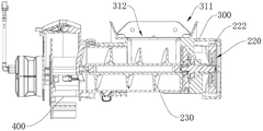
Referring to fig. 2-4, the sowing system 10 includes a container 100, a conveyor 200, and a sowing device 400. The conveying device 200 includes a driving motor 210, a transmission assembly 220, a conveying assembly 230, and the feeding housing 300. The storage container 100 is connected to the feeding housing 300 for storing the material. The storage container 100 is provided with a discharge hole for discharging the material to the feeding housing 300. The driving motor 210, the transmission assembly 220 and the conveying assembly 230 are all arranged on the feeding shell 300, the driving motor 210 is in transmission connection with the conveying assembly 230 through the transmission assembly 220 and is used for driving the conveying assembly 230 to convey materials in the feeding shell 300 through the transmission assembly 220, the conveying assembly 230 is connected with the scattering device 400, the conveying assembly 230 conveys the materials to the scattering device 400, and the scattering device 400 scatters the materials, so that the scattering operation of the materials is completed.
The number of the conveying assemblies 230 and the spreading devices 400 is two, and the two conveying assemblies 230 and the two spreading devices 400 are connected in a one-to-one correspondence. Alternatively, the conveyor assembly 230 may be capable of auger delivery to convey the material within the feeder housing 300 to the spreading device 400.
The transmission assembly 220 may include a driving gear 221 and two driven gears 222, the driving gear 221 is in transmission connection with an output shaft of the driving motor 210, and the driving gear 221 is respectively engaged with the two driven gears 222. The two driven gears 222 are respectively connected with the two transmission assemblies 230 in a one-to-one correspondence manner. The driving motor 210 drives the driving gear 221, the driving gear 221 drives the driven gear 222, and the driven gear 222 drives the conveying assembly 230 to rotate, so as to convey the material.
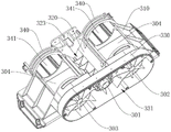
Referring to fig. 5 and 6, the feeding housing 300 includes a housing body 310, a partition 320, a transmission housing 330, and a fixing housing 340. Wherein, the transmission housing 330 and the fixed housing 340 are respectively connected with both sides of the case body 310. The partition 320 is disposed in the case body 310 and connected to the case body 310. It should be noted that the feeding housing 300 is integrally formed, that is, the housing body 310, the partition 320, the transmission housing 330 and the fixing housing 340 are integrally formed to form a whole. Can be favorable to reducing assembly work load, the structure integrates the degree height, makes pay-off casing 300 structure compacter.
Wherein, the housing body 310 is provided with a feed inlet 311 and a containing cavity 312. The inlet 311 is disposed corresponding to the outlet of the storage container 100. It should be understood that the housing body 310 is connected to the storage container 100, and the inlet 311 may be located below the outlet of the storage container 100 or may communicate with the outlet of the storage container 100. The number of the accommodating cavities 312 comprises two, the two accommodating cavities 312 are communicated with the feed inlet 311, and the two accommodating cavities 312 are used for installing the conveying assembly 230 capable of conveying materials. The transmission assembly 230 is at least partially received in the receiving cavity 312, and one end of the transmission assembly extends out of the receiving cavity 312 and is connected to the sowing device 400. In this way, the material falling from the discharge port of the storage container 100 can enter the two receiving cavities 312 through the feed port 311, so that the conveying assemblies 230 in the two receiving cavities 312 respectively convey the material until the material is conveyed to the corresponding spreading devices 400.
It should be noted that the housing body 310 is integrally formed, and both of the two receiving cavities 312 are communicated with the feeding hole 311. Like this, can be integrated together two receipts chamber 312, two are acceptd chamber 312 and can share feed inlet 311, and the material of storing container 100 output can get into two by feed inlet 311 like this and accept the chamber 312 in, can effectively improve the synchronism of feeding to improve the synchronism that the material was scattered, improve and scatter the effect.
In addition, the number of the receiving cavities 312 in the embodiment of the present invention includes two, it is considered that the number of the receiving cavities 312 may be two, three, or more, when the number of the receiving cavities 312 is greater than two, the corresponding conveying assemblies 230 and the spreading devices 400 are correspondingly increased, the plurality of receiving cavities 312 may be sequentially arranged, and the structure between any two adjacent receiving cavities 312 is similar to the structure of the two receiving cavities 312, so the embodiment only takes the case of two receiving cavities 312 as an example, and should not be understood as a specific limitation on the number of the receiving cavities 312.
In this embodiment, the housing body 310 is provided with a top wall 313, the feeding port 311 is opened on the top wall 313, and the two accommodating cavities 312 are opened upwards and are communicated with the feeding port 311 on the top wall 313. The feed opening 311 may be opened to a larger extent, in this embodiment, only a portion of the peripheral edge of the top wall 313 is left, and the rest of the top wall is opened to form the feed opening 311, so that the material output from the storage container 100 can more easily enter the two receiving cavities 312 through the feed opening 311.
The housing body 310 may include a first sidewall 314, a second sidewall 315, a first end wall 316, and a second end wall 317. The first side wall 314 is disposed opposite to the second side wall 315, one end of the first side wall 314 is connected to one end of the second side wall 315 by a first end wall 316, and the other end of the first side wall 314 is connected to the other end of the second side wall 315 by a second end wall 317. The top sides of the first side wall 314, the second side wall 315, the first end wall 316 and the second end wall 317 are all connected to the top wall 313, thereby forming a substantially rectangular feed opening 311 in the top wall 313.
The partition 320 is disposed in the housing body 310 and divides the internal cavity of the housing body 310 into two receiving cavities 312. Two containing cavities 312 can be defined by the partition 320, optionally, the top of the partition 320 may have a predetermined distance from the top wall 313 in the height direction, for example, may be slightly lower than the top wall 313, so that the top spaces of the two containing cavities 312 are communicated with each other through the space above the top of the partition 320 and are simultaneously communicated with the feed opening 311, and therefore, one feed opening 311 may be simultaneously communicated with the two containing cavities 312.
It should be noted that, in other embodiments, if the number of the receiving cavities 312 is greater than two, the partition 320 may be disposed between two adjacent receiving cavities 312, so as to define two adjacent receiving cavities 312.
The partition 320 has an inverted V-shaped longitudinal section, and two ends of the partition are connected to the first side wall 314 and the second side wall 315, respectively. The partition 320 may include first and second guide surfaces 321 and 322 disposed opposite to each other. The first side wall 314, the first end wall 316, the second side wall 315 and the first guide surface 321 together define one of the receiving cavities 312, and the first side wall 314, the second end wall 317, the second side wall 315 and the second guide surface 322 together define the other receiving cavity 312. By arranging the first guide surface 321 and the second guide surface 322, the material entering the receiving cavity 312 from the feeding hole 311 can be received and guided into the conveying assembly 230.
Alternatively, the first guide surface 321 and the second guide surface 322 are both obliquely disposed, and a top side of the first guide surface 321 and a top side of the second guide surface 322 are connected and form an inverted V-shaped structure. That is, the first guide surface 321 and the second guide surface 322 are connected to form an inverted V-shaped structure, so that the materials on the first guide surface 321 and the second guide surface 322 respectively fall into the conveying assembly 230 in the directions away from each other. Further, the first end wall 316 and the second end wall 317 are both disposed obliquely, the first end wall 316 and the first guiding surface 321 form a funnel-shaped wall surface, the second end wall 317 and the second guiding surface 322 form a funnel-shaped wall surface, and the first end wall 316 and the second end wall 317 can also guide the material, so as to guide the material into the conveying assembly 230 at the bottom of the receiving cavity 312.
Referring to fig. 7, a mounting cavity 323 is formed by recessing a side of the partition 320 opposite to the receiving cavity 312, and the mounting cavity 323 is used for receiving and mounting the driving motor 210 in transmission connection with the transmission assembly 230. It is understood that the mounting cavity 323 is formed at the rear of the inverted V-shaped structure formed by the first and second guide surfaces 321 and 322.
By forming the mounting cavity 323 for mounting the driving motor 210 on the partition 320, the driving motor 210 can be mounted on the feeding housing 300 and accommodated in the mounting cavity 323, so that the structure is more compact and the layout is more reasonable.
Referring to fig. 5-7, the transmission housing 330 is disposed on one side of the housing body 310 and has a substantially racetrack-shaped housing structure. The transmission housing 330 is provided with a matching cavity 331 therein, and the matching cavity 331 is respectively communicated with the mounting cavity 323 and the accommodating cavity 312, and is used for accommodating and mounting the transmission assembly 220 in transmission connection with the transmission assembly 230. The transmission assembly 220 is arranged in the matching cavity 331, so that the transmission assembly 220 is positioned on one side of the shell body 310, the structure is more compact, and the layout is more reasonable.
In this embodiment, the transmission housing 330 and the outer sidewall of the casing body 310 jointly enclose a fitting cavity 331. The outer side wall of the housing body 310 for forming the matching cavity 331 is provided with a first through hole 301, a second through hole 302 and a third through hole 303, wherein the first through hole 301 is located between the second through hole 302 and the third through hole 303, and the second through hole 302, the first through hole 301 and the third through hole 303 are sequentially arranged. The fitting cavity 331 communicates with the mounting cavity 323 through the first through hole 301, communicates with one of the receiving cavities 312 through the second through hole 302, and communicates with the other receiving cavity 312 through the third through hole 303. Further, the driving gear 221 and the two driven gears 222 are accommodated in the matching cavity 331, and the driving gear 221 is located between the two driven gears 222. The driving gear 221 is disposed at the first through hole 301, so that the driving motor 210 is connected to the driving gear 221 through a connection structure passing through the first through hole 301. Similarly, the two driven gears 222 are respectively disposed at the second through hole 302 and the third through hole 303, so that the transmission assemblies 230 in the two receiving cavities 312 are respectively connected with the driven gears 222 through the connection structure passing through the second through hole 302 and the connection structure passing through the third through hole 303. Therefore, transmission can be realized, and the structure can be compact. The connection structure passing through the through hole is not particularly limited as long as the driving gear 221 and the driving motor 210 can be in transmission connection, and the driven gear 222 and the transmission assembly 230 can be in transmission connection.
The fixed casing 340 is disposed on a side of the casing body 310 away from the transmission casing 330, and the fixed casing 340 is substantially a circular casing structure. The fixed housing 340 is provided with a plug channel 341 therein, and the plug channel 341 is communicated with the receiving cavity 312 for the transmission assembly 230 to be inserted into the receiving cavity 312. In this embodiment, two fixed housings 340 are provided, and each of the two fixed housings 340 is provided with an insertion passage 341 through which one of the transfer assemblies 230 is inserted into the receiving cavity 312 until the transfer assembly 230 is matched with the connection structure passing through the second through hole 302 and the connection structure passing through the third through hole 303, so as to achieve transmission connection with the driven gear 222. For example, a plug-in fit may be used between the transfer assembly 230 and the connection structure through the through-hole. In this embodiment, by arranging the fixing housing 340, the conveying assembly 230 can be conveniently inserted into the accommodating cavity 312 through the inserting passage 341, so that the conveying assembly 230 is convenient to install, compact in overall structure and more reasonable in layout.
Referring to fig. 8, the transfer assembly 230 includes an outer sleeve 231 and an auger 232 disposed within the outer sleeve 231. The outer sleeve 231 has a substantially cylindrical structure, and the shape of the outer sleeve matches the shape of the plug channel 341, so that the outer sleeve can be inserted into the plug channel 341 and the installation is stable. The auger 232 is in transmission connection with the driven gear 222 when the outer sleeve 231 is inserted into the receiving cavity 312, and the top opening of the outer sleeve 231 is used for allowing the falling materials guided by the first guide surface 321 and the first end wall 316 to pass through or allowing the falling materials guided by the second guide surface 322 and the second end wall 317 to pass through, so that the materials fall into the outer sleeve 231, and the auger 232 performs spiral conveying. One end of the outer sleeve 231 is communicated with the scattering device 400, so that the materials conveyed by the auger 232 enter the scattering device 400 for scattering.
With reference to fig. 5-7, in addition, a material leaking hole 304 corresponding to the feeding hole 311 is formed at the bottom of each accommodating cavity 312. When the conveying assembly 230 is inserted into the accommodating cavity 312, the outer sleeve 231 can shield the material leaking hole 304, and if part of the material enters between the outer sleeve 231 and the inner wall of the accommodating cavity 312 and is difficult to be conveyed by the auger 232, the material can be discharged through the material leaking hole 304, so that parts such as a transmission bearing in the spreading system 10 are difficult to abrade and corrode. When the conveying assembly 230 is pulled out of the accommodating cavity 312, the material in the storage container 100 can fall out along the material leakage hole 304, and the storage container 100 does not need to be provided with other holes for cleaning the material.
In summary, according to the feeding housing 300, the scattering system 10 and the unmanned device 1 provided by the embodiment of the utility model, the feeding housing 300 is integrally formed, for example, the housing body 310, the partition 320, the transmission housing 330 and the fixing housing 340 are integrally formed, and both of the two accommodating cavities 312 are communicated with the feeding port 311, and the two accommodating cavities 312 can share the feeding port 311, so that the material output from the storage container 100 can enter the two accommodating cavities 312 through the feeding port 311, and the synchronism of feeding can be effectively improved, thereby improving the synchronism of material scattering and the scattering effect of scattering. In addition, the partition part 320 can separate the two accommodating cavities 312 and effectively guide the materials, and the mounting cavity 323 on the back side of the partition part is convenient for accommodating the driving motor 210. The transmission housing 330 and the fixed housing 340 are arranged reasonably, so as to accommodate the transmission assembly 220 and facilitate the installation of the transmission assembly 230. Therefore, the feeding shell 300 is more compact in overall structure and can enable the layout of parts to be more reasonable.
The above description is only a preferred embodiment of the present invention and is not intended to limit the present invention, and various modifications and changes may be made by those skilled in the art. Any modification, equivalent replacement, or improvement made within the spirit and principle of the present invention should be included in the protection scope of the present invention.