CN216783462U - End face cleaning and maintaining device for urban rail wheel - Google Patents
End face cleaning and maintaining device for urban rail wheel Download PDFInfo
- Publication number
- CN216783462U CN216783462U CN202220473469.7U CN202220473469U CN216783462U CN 216783462 U CN216783462 U CN 216783462U CN 202220473469 U CN202220473469 U CN 202220473469U CN 216783462 U CN216783462 U CN 216783462U
- Authority
- CN
- China
- Prior art keywords
- horizontal cavity
- water
- fixedly connected
- cavity
- side wall
- Prior art date
- Legal status (The legal status is an assumption and is not a legal conclusion. Google has not performed a legal analysis and makes no representation as to the accuracy of the status listed.)
- Expired - Fee Related
Links
Images


Landscapes
- Cleaning In General (AREA)
Abstract
城轨车轮用端面清洁维护装置,涉及城轨车轮维护技术领域,包括推车,推车的顶面设置有竖直腔,竖直腔上通过升降机构连接有水平腔,水平腔的侧壁中部转动连接有转杆,转杆位于水平腔外部的一端可拆卸的连接有刷头,水平腔内中部设置有带动转杆进行转动的驱动机构,水平腔上还安装有喷水机构和烘干机构,喷水机构和烘干机构分别位于所述刷头的两侧。本实用新型中通过推车推动该装置,先使喷水机构先对车轮端面进行喷水,再使刷头的刷毛与车轮端面相接触,启动驱动电机带动刷头转动,进而对车轮的端面进行清洗,清洗过后推动该推车使烘干机构对着车轮端面进行烘干,保证清洗后的车轮端面处于洁净干燥。
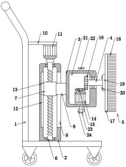
The utility model relates to an end face cleaning and maintenance device for urban rail wheels, which relates to the technical field of urban rail wheel maintenance, and includes a cart. The top surface of the cart is provided with a vertical cavity. A rotating rod is rotatably connected, and one end of the rotating rod located outside the horizontal cavity is detachably connected with a brush head. A driving mechanism is arranged in the middle of the horizontal cavity to drive the rotating rod to rotate, and a water spray mechanism and a drying mechanism are also installed on the horizontal cavity. , the water spray mechanism and the drying mechanism are respectively located on both sides of the brush head. In the utility model, the device is pushed by a cart, the water spray mechanism first sprays water on the end face of the wheel, and then the bristles of the brush head are in contact with the end face of the wheel, and the driving motor is started to drive the brush head to rotate, and then the end face of the wheel is sprayed with water. After cleaning, push the trolley to make the drying mechanism dry against the end surface of the wheel to ensure that the end surface of the wheel after cleaning is clean and dry.
Description
技术领域technical field
本实用新型涉及城轨车轮维护技术领域,具体涉及城轨车轮用端面清洁维护装置。The utility model relates to the technical field of urban rail wheel maintenance, in particular to an end surface cleaning and maintenance device for urban rail wheels.
背景技术Background technique
城轨的车轮需要进行定期的保养和维护,在这之前需要对城轨的车轮进行清洗,将其表面沾上的泥等清洗掉,目前在城轨车轮进行清洗时通常采用人工,人工清洗工作效率低且清洗效果较差,目前急需一种可以替代人工的清洁维护装置对城轨车轮端面清洁。The wheels of the urban rail need to be regularly maintained and maintained. Before that, the wheels of the urban rail need to be cleaned to remove the mud on the surface. At present, the wheels of the urban rail are usually cleaned manually. Manual cleaning work The efficiency is low and the cleaning effect is poor. At present, there is an urgent need for a cleaning and maintenance device that can replace manual cleaning of the end surfaces of urban rail wheels.
实用新型内容Utility model content
针对上述存在的问题,本实用新型提供城轨车轮用端面清洁维护装置。In view of the above existing problems, the utility model provides an end surface cleaning and maintenance device for urban rail wheels.
技术方案为:包括推车,所述推车的顶面设置有竖直腔,所述竖直腔上通过升降机构连接有水平腔,所述水平腔的侧壁中部转动连接有转杆,所述转杆位于所述水平腔外部的一端可拆卸的连接有刷头,所述水平腔内中部设置有带动所述转杆进行转动的驱动机构,所述水平腔上还安装有喷水机构和烘干机构,所述喷水机构和烘干机构分别位于所述刷头的两侧。The technical solution is: comprising a cart, the top surface of the cart is provided with a vertical cavity, the vertical cavity is connected with a horizontal cavity through a lifting mechanism, and a rotating rod is rotatably connected to the middle of the side wall of the horizontal cavity, so A brush head is detachably connected to one end of the rotating rod outside the horizontal cavity, a driving mechanism for driving the rotating rod to rotate is arranged in the middle of the horizontal cavity, and a water spray mechanism and a water spraying mechanism are also installed on the horizontal cavity. A drying mechanism, the water spraying mechanism and the drying mechanism are respectively located on both sides of the brush head.
优选地,所述升降机构包括转动连接在所述竖直腔内部的螺纹杆,所述螺纹杆上通过螺纹连接有螺纹套,所述螺纹套的侧壁固定连接有连杆,所述连杆贯穿所述竖直腔侧壁的长条孔并与所述水平腔的侧壁固定连接,所述推车上固定连接有电机板,所述电机板的底面安装有动力电机,所述螺纹杆的顶部贯穿所述竖直腔的顶面并与所述动力电机的输出轴固定连接。Preferably, the lifting mechanism includes a threaded rod rotatably connected inside the vertical cavity, a threaded sleeve is threadedly connected to the threaded rod, a connecting rod is fixedly connected to a side wall of the threaded sleeve, and the connecting rod The long hole penetrates through the side wall of the vertical cavity and is fixedly connected to the side wall of the horizontal cavity. The cart is fixedly connected with a motor plate, and a power motor is installed on the bottom surface of the motor plate. The threaded rod The top of the vertical cavity penetrates through the top surface of the vertical cavity and is fixedly connected with the output shaft of the power motor.
优选地,所述竖直腔的侧壁开设有滑槽,所述螺纹套的侧壁固定连接有与所述滑槽相配合滑动的滑块。Preferably, the side wall of the vertical cavity is provided with a sliding groove, and the side wall of the threaded sleeve is fixedly connected with a sliding block which cooperates with the sliding groove and slides.
优选地,所述驱动机构包括安装在所述水平腔内部的驱动电机,所述驱动电机的输出轴固定连接主动锥齿轮,所述转杆位于所述水平腔内部的一端固定连接有从动锥齿轮,所述主动锥齿轮与所述从动锥齿轮相啮合。Preferably, the drive mechanism includes a drive motor installed inside the horizontal cavity, an output shaft of the drive motor is fixedly connected with a driving bevel gear, and an end of the rotating rod located inside the horizontal cavity is fixedly connected with a driven cone gear, the driving bevel gear meshes with the driven bevel gear.
优选地,所述刷头包括刷板,所述刷板上设置有若干刷毛,所述转杆位于所述水平腔外部的一端固定连接有连接板,所述刷板与所述连接板通过若干螺栓固定连接。Preferably, the brush head includes a brush plate, a number of bristles are arranged on the brush plate, a connecting plate is fixedly connected to one end of the rotating rod outside the horizontal cavity, and the brush plate and the connecting plate pass through several Bolted connection.
优选地,所述喷水机构包括安装在所述水平腔内部的水箱,所述水箱的顶面和底面分别连通有进水管、出水管,所述出水管上安装有出水阀门,所述水箱的侧壁固定连接有抽水管,所述抽水管位于所述水箱内部的一端延伸至所述水箱内部底面,所述水平腔的侧壁固定连接有喷水管,所述水平腔内侧壁安装有液泵,所述液泵的进水端与所述抽水管连接,所述液泵的出水端与所述喷水管连接,所述喷水管的末端连接有喷水头,所述喷水头上安装有若干喷嘴。Preferably, the water spraying mechanism includes a water tank installed inside the horizontal cavity, the top surface and the bottom surface of the water tank are respectively connected with a water inlet pipe and a water outlet pipe, and a water outlet valve is installed on the water outlet pipe. The side wall is fixedly connected with a water suction pipe, and one end of the water suction pipe located inside the water tank extends to the bottom surface of the water tank, the side wall of the horizontal cavity is fixedly connected with a water spray pipe, and the inner side wall of the horizontal cavity is installed with a liquid pump, the water inlet end of the liquid pump is connected with the water suction pipe, the water outlet end of the liquid pump is connected with the water spray pipe, the end of the water spray pipe is connected with a water spray head, the water spray head Several nozzles are installed on it.
优选地,所述进水管的顶部盖合有顶盖。Preferably, the top cover of the water inlet pipe is closed with a top cover.
优选地,所述烘干机构包括安装在所述水平腔内部的热风机,所述水平腔的侧壁固定连接有送风管,所述热风机的出风口与所述送风管连接。Preferably, the drying mechanism includes a hot air blower installed inside the horizontal cavity, an air supply pipe is fixedly connected to the side wall of the horizontal cavity, and an air outlet of the hot air blower is connected to the air supply pipe.
本实用新型提供城轨车轮用端面清洁维护装置,与现有技术相比有益效果为:The utility model provides an end surface cleaning and maintenance device for urban rail wheels, and compared with the prior art, the beneficial effects are as follows:
(1):本实用新型中通过推车推动该装置,先使喷水机构先对车轮端面进行喷水,再使刷头的刷毛与车轮端面相接触,启动驱动电机带动刷头转动,进而对车轮的端面进行清洗,清洗过后推动该推车使烘干机构对着车轮端面进行烘干,保证清洗后的车轮端面处于洁净干燥;(1): In this utility model, the device is pushed by a cart, and the water spray mechanism is first used to spray water on the end face of the wheel, and then the bristles of the brush head are in contact with the end face of the wheel, and the driving motor is started to drive the brush head to rotate, and then the brush head is rotated. The end face of the wheel is cleaned, and after cleaning, the cart is pushed to make the drying mechanism dry against the end face of the wheel to ensure that the end face of the wheel is clean and dry;
(2):本实用新型中刷毛、喷水机构、烘干机构的高度可根据清洗车轮的需要进行调节,为使用带来便利。(2): The heights of the bristles, the water spraying mechanism and the drying mechanism in the utility model can be adjusted according to the needs of cleaning the wheels, which brings convenience for use.
附图说明Description of drawings
图1:是本实用新型中整体结构图。Figure 1: is the overall structure diagram of the utility model.
图2:是本实用新型中整体侧视图。Figure 2: is the overall side view of the utility model.
图3:是本实用新型中水平腔内部俯视图。Figure 3: is a top view of the interior of the horizontal cavity in the present invention.
图4:是本实用新型中水平腔外部侧视图。Figure 4: is the external side view of the horizontal cavity in the utility model.
图中:1-推车、2-竖直腔、3-水平腔、4-转杆、5-刷头、6-螺纹杆、7-螺纹套、8-连杆、9-长条孔、10-电机板、11-动力电机、12-滑槽、13-滑块、14-驱动电机、15-主动锥齿轮、16-从动锥齿轮、17-刷板、18-刷毛、19-连接板、20-螺栓、21-水箱、22-进水管、23-出水管、24-出水阀门、25-抽水管、26-喷水管、27-液泵、28-喷水头、29-喷嘴、30-顶盖、31-送风管、32-热风机。In the picture: 1-cart, 2-vertical cavity, 3-horizontal cavity, 4-rotating rod, 5-brush head, 6-threaded rod, 7-threaded sleeve, 8-connecting rod, 9-long hole, 10-motor plate, 11-power motor, 12-chute, 13-slider, 14-drive motor, 15-drive bevel gear, 16-driven bevel gear, 17-brush plate, 18-bristles, 19-connection Plate, 20-bolt, 21-water tank, 22-water inlet pipe, 23-water outlet pipe, 24-water outlet valve, 25-water pumping pipe, 26-water spray pipe, 27-liquid pump, 28-water spray head, 29-nozzle , 30-top cover, 31-air supply pipe, 32-hot air blower.
具体实施方式Detailed ways
以下将结合附图对本实用新型各实施例的技术方案进行清楚、完整的描述,显然,所描述的实施例仅仅是本实用新型的一部分实施例,而不是全部的实施例。基于本实用新型的实施例,本领域普通技术人员在没有做出创造性劳动的前提下所得到的所有其它实施例,都属于本实用新型所保护的范围,在本实用新型的描述中,需要说明的是,术语“中心”、“上”、“下”、“左”、“右”、“竖直”、“水平”、“内”、“外”等指示的方位或位置关系为基于附图所示的方位或位置关系,仅是 为了便于描述本实用新型和简化描述,而不是指示或暗示所指的装置或元件必须具有特定的方位、以特定的方位构造和操作,因此不能理解为对本实用新型的限制。The technical solutions of the embodiments of the present invention will be clearly and completely described below with reference to the accompanying drawings. Obviously, the described embodiments are only a part of the embodiments of the present invention, rather than all the embodiments. Based on the embodiments of the present utility model, all other embodiments obtained by those of ordinary skill in the art without creative work fall within the scope of protection of the present utility model. In the description of the present utility model, it is necessary to explain It should be noted that the orientation or positional relationship indicated by the terms "center", "upper", "lower", "left", "right", "vertical", "horizontal", "inner", "outer", etc. The orientation or positional relationship shown in the figures is only for the convenience of describing the present invention and simplifying the description, rather than indicating or implying that the device or element referred to must have a specific orientation, be constructed and operated in a specific orientation, and therefore cannot be understood as Limitations of the present invention.
此外,术语“第一”、“第二”、“第三”仅用于描述目的,而不能理解为指示或暗示相对重要性在本实用新型的描述中,需要说明的是,除非另有明确的规定和限定,术语“安装”、“相连”、“连接”应做广义理解,例如,可以是固定连接,也可以是可拆卸连接,或一体地连接;可以是机械连接,也可以是电连接;可以是直接相连,也可以通过中间媒介间接相连,可以是两个元件内部的连通。对于本领域的普通技术人员而言,可以具体情况理解上述术语在本实用新型中的具体含义。In addition, the terms "first", "second" and "third" are only used for descriptive purposes, and should not be construed as indicating or implying relative importance. In the description of the present invention, it should be noted that unless otherwise specified The terms "installed", "connected" and "connected" should be understood in a broad sense, for example, it may be a fixed connection, a detachable connection, or an integral connection; it may be a mechanical connection or an electrical connection. Connection; it can be a direct connection, or an indirect connection through an intermediate medium, or the internal connection of two elements. For those of ordinary skill in the art, the specific meanings of the above terms in the present invention can be understood in specific situations.
下面通过具体的实施例子并结合附图对本实用新型做进一步的详细描述。The present utility model will be further described in detail below through specific embodiments and in conjunction with the accompanying drawings.
实施例一、如图1和2所示,城轨车轮用端面清洁维护装置,包括推车1,推车1采用现有技术,推车1的顶面设置有竖直腔2,竖直腔2焊接在推车1的顶面,竖直腔2上通过升降机构连接有水平腔3。
在本实施例中,升降机构包括通过轴承转动连接在竖直腔2内部的螺纹杆6,螺纹杆6上通过螺纹连接有螺纹套7,螺纹套7的侧壁焊接固定连接有连杆8,连杆8贯穿竖直腔2侧壁的长条孔9并与水平腔3的侧壁焊接固定连接,推车1上焊接固定连接有电机板10,电机板10的底面安装有动力电机11,动力电机11采用现有技术,动力电机11通过螺栓固定连接在电机板10的底面,螺纹杆6的顶部贯穿竖直腔2的顶面并与动力电机11的输出轴通过联轴器固定连接。In this embodiment, the lifting mechanism includes a threaded
竖直腔2的侧壁开设有滑槽12,螺纹套7的侧壁固定连接有与滑槽12相配合滑动的滑块13,滑块13与螺纹套7采用焊接固定连接。The side wall of the
升降机构工作原理:启动动力电机11,动力电机11带动螺纹杆6转动,螺纹杆6转动带动螺纹套7沿其上下移动,螺纹套7带动水平腔3上下移动。The working principle of the lifting mechanism: start the
水平腔3的侧壁中部通过轴承转动连接有转杆4,转杆4位于水平腔3外部的一端可拆卸的连接有刷头5,在本实施例中,刷头5包括刷板17,刷板17上设置有若干刷毛18,若干刷毛18通过胶水粘结在刷板17上,转杆4位于水平腔3外部的一端焊接固定连接有连接板19,刷板17与连接板19通过若干螺栓20固定连接。刷头5可进行拆卸,方便对刷头5进行更换。The middle of the side wall of the
如图3和4所示,水平腔3内中部设置有带动转杆4进行转动的驱动机构,在本实施例中驱动机构包括安装在水平腔3内部的驱动电机14,驱动电机14采用现有技术,驱动电机14通过螺钉固定在水平腔3内部,驱动电机14的输出轴固定连接主动锥齿轮15,主动锥齿轮15的中心孔与驱动电机14的输出轴通过键连接,转杆4位于水平腔3内部的一端固定连接有从动锥齿轮16,从动锥齿轮16的中心孔与转杆4焊接固定连接,主动锥齿轮15与从动锥齿轮16相啮合。启动驱动电机14,驱动电机14可带动主动锥齿轮15转动,主动锥齿轮15转动带动从动锥齿轮16转动,从动锥齿轮16转动带动转杆4转动,转杆4转动带动刷头5进行转动。As shown in Figures 3 and 4, a driving mechanism for driving the rotating
水平腔3上还安装有喷水机构和烘干机构,喷水机构和烘干机构分别位于刷头5的两侧。A water spray mechanism and a drying mechanism are also installed on the
在本实施例中,喷水机构包括安装在水平腔3内部的水箱21,水箱21可通过螺钉固定连接在水平腔3内部,水箱21的顶面和底面分别连通有进水管22、出水管23,进水管22、出水管23与水箱21一体成型设置,出水管23上安装有出水阀门24,出水阀门24采用现有技术。进水管22的顶部盖合有顶盖30,顶盖30通过螺纹连接在进水管22的顶部。进水管22用于向水箱21内部清洁水,出水管23用于将水箱21内部的水排出。In this embodiment, the water spraying mechanism includes a
水箱21的侧壁固定连接有抽水管25,抽水管25贯穿水箱21的侧壁并与水箱21采用焊接固定连接,抽水管25位于水箱21内部的一端延伸至水箱21内部底面。水平腔3的侧壁固定连接有喷水管26,喷水管26贯穿水平腔3的侧壁并与水平腔3焊接固定连接,水平腔3内侧壁安装有液泵27,液泵27采用现有技术,液泵27通过螺钉固定在水平腔3内侧壁,液泵27的进水端与抽水管25通过现有技术中的管箍固定连接,液泵27的出水端与喷水管26通过现有技术中的管箍连接,喷水管26的末端通过螺纹连接有喷水头28,喷水头28上安装有若干喷嘴29,喷嘴29通过螺纹连接在喷水头28上。The side wall of the
在本实施例中,烘干机构包括安装在水平腔3内部的热风机32,热风机32采用现有技术,热风机32通过螺钉固定在水平腔3内部,水平腔3的侧壁固定连接有送风管31,送风管31贯穿水平腔3的侧壁并与水平腔3焊接固定连接,热风机32的出风口与送风管31通过现有技术中的气体管道连接器连接。In this embodiment, the drying mechanism includes a
工作原理:本实用新型中通过推车1推动该装置,先使喷水机构先对车轮端面进行喷水,再使刷头5的刷毛18与车轮端面相接触,启动驱动电机14带动刷头5转动,进而对车轮的端面进行清洗,清洗过后推动该推车使烘干机构对着车轮端面进行烘干,保证清洗后的车轮端面处于洁净干燥;且通过升降机构可以调节刷毛18、喷水机构、烘干机构的高度,可根据实际车轮的高度进行调节,为使用带来便利。Working principle: In this utility model, the device is pushed by the
尽管结合优选实施方案具体展示和介绍了本实用新型,具体实现该技术方案方法和途径很多,以上所述仅是本实用新型的优选实施方式,但所属领域的技术人员应该明白,在不脱离所附权利要求书所限定的本实用新型的精神和范围内,在形式上和细节上可以对本实用新型做出各种变化,均为本实用新型的保护范围。Although the present invention has been specifically shown and introduced in conjunction with the preferred embodiments, there are many methods and approaches to realize the technical solution. Various changes can be made to the present utility model in form and detail within the spirit and scope of the present utility model defined by the appended claims, which are all within the protection scope of the present utility model.
Claims (8)
Priority Applications (1)
| Application Number | Priority Date | Filing Date | Title |
|---|---|---|---|
| CN202220473469.7U CN216783462U (en) | 2022-03-07 | 2022-03-07 | End face cleaning and maintaining device for urban rail wheel |
Applications Claiming Priority (1)
| Application Number | Priority Date | Filing Date | Title |
|---|---|---|---|
| CN202220473469.7U CN216783462U (en) | 2022-03-07 | 2022-03-07 | End face cleaning and maintaining device for urban rail wheel |
Publications (1)
| Publication Number | Publication Date |
|---|---|
| CN216783462U true CN216783462U (en) | 2022-06-21 |
Family
ID=82000768
Family Applications (1)
| Application Number | Title | Priority Date | Filing Date |
|---|---|---|---|
| CN202220473469.7U Expired - Fee Related CN216783462U (en) | 2022-03-07 | 2022-03-07 | End face cleaning and maintaining device for urban rail wheel |
Country Status (1)
| Country | Link |
|---|---|
| CN (1) | CN216783462U (en) |
Cited By (1)
| Publication number | Priority date | Publication date | Assignee | Title |
|---|---|---|---|---|
| CN115743046A (en) * | 2022-12-28 | 2023-03-07 | 深圳巴士集团股份有限公司第三分公司 | Rim cleaning equipment |
-
2022
- 2022-03-07 CN CN202220473469.7U patent/CN216783462U/en not_active Expired - Fee Related
Cited By (1)
| Publication number | Priority date | Publication date | Assignee | Title |
|---|---|---|---|---|
| CN115743046A (en) * | 2022-12-28 | 2023-03-07 | 深圳巴士集团股份有限公司第三分公司 | Rim cleaning equipment |
Similar Documents
| Publication | Publication Date | Title |
|---|---|---|
| CN212190454U (en) | Oil smoke pipeline cleaning robot | |
| CN211381122U (en) | A walking support type shopping mall cleaning sweeper | |
| CN210925207U (en) | Modeling device for architectural design | |
| CN216854596U (en) | Efficient cleaning mechanism for wall climbing robot | |
| CN211420996U (en) | Watering dust removal type road cleaning device | |
| CN112315388A (en) | House building wall cleaning device | |
| CN208250992U (en) | A kind of road guardrail cleaning device | |
| CN217419534U (en) | A kind of water conservancy project with sand blocking and water intake gate | |
| CN219638511U (en) | Device for cleaning swimming pool | |
| CN216728659U (en) | Air source heat pump's dirt treatment facility | |
| CN216275430U (en) | Stubborn stain cleaning device is used in tourist attraction | |
| CN217141595U (en) | Cleaning device for polysilicon storage tank equipment | |
| CN213286148U (en) | A kind of dust suppression equipment for construction site | |
| CN209237514U (en) | A kind of sewage precipitation device | |
| CN219541131U (en) | A cleaning device for chemical plant equipment | |
| CN115653332A (en) | Concrete building sprays maintenance system | |
| CN111701921B (en) | Automatic cleaning equipment for elevator car | |
| CN112568775B (en) | Small hand-push type glass scrubbing device capable of scrubbing inside and outside positively and negatively | |
| CN220705207U (en) | Concrete pumping equipment | |
| CN220786899U (en) | Storage tank convenient to clearance mud | |
| CN220970087U (en) | Special mould cleaning equipment of concrete production | |
| CN220468588U (en) | A highway bridge maintenance device | |
| CN218027077U (en) | Spraying device for concrete road maintenance | |
| CN212438489U (en) | Full-automatic ground cleaning device | |
| CN220615779U (en) | Cleaning structure for external overhaul of motor train unit |
Legal Events
| Date | Code | Title | Description |
|---|---|---|---|
| GR01 | Patent grant | ||
| GR01 | Patent grant | ||
| CF01 | Termination of patent right due to non-payment of annual fee | ||
| CF01 | Termination of patent right due to non-payment of annual fee |
Granted publication date: 20220621 |