Disclosure of Invention
The utility model aims to provide a 16+16 high-power full-power gear shifting gearbox, all gears can realize full-power gear shifting and power reversing, and the gearbox is complete in function, compact in structure, low in manufacturing cost and high in operating efficiency.
A16 +16 high-power full-power gear-shifting gearbox comprises a main speed changing device, an auxiliary speed changing device and a power output device, wherein the input end of the main speed changing device is connected with an output shaft of a main clutch, the output end of the main speed changing device is connected with the input end of the auxiliary speed changing device, and the output end of the auxiliary speed changing device is connected with the input end of the central transmission of a rear axle; the main transmission device is internally provided with a power input shaft S1, a second shaft S2 and a third shaft S3, and the three shafts are arranged in a triangular shape when viewed from the direction of the engine; the auxiliary transmission device comprises a four-shaft S4 and a five-shaft S5, wherein the four-shaft S4 is coaxial with the two-shaft S2, and the two shafts are connected through a spline sleeve. In addition, the PTO shaft S6 is coaxial with the power input shaft S1, and the two shafts are connected through a spline sleeve; the twenty-first gear 21 is fixedly connected to the power output shaft S7.
The power input shaft S1 is sequentially provided with a first gear 1, a first wet clutch C1, a third gear 3, a second wet clutch C2, a sixth gear 6 and a gear pump power take-off gear 12 from left to right; the first gear 1 and the gear pump power take-off gear 12 are fixedly connected to the power input shaft S1, the right end face of the first gear 1 is fixedly connected with an external spline, and the friction plate slides on the external spline; the third gear 3 and the sixth gear 6 are sleeved on the power input shaft S1, the left end face of the sixth gear 6 is fixedly connected with an external spline, and the friction plate slides on the external spline; the outer hubs of the first wet clutch C1 and the second wet clutch C2 are fixed to the left and right ends of the third gear 3, respectively. The electro-hydraulic control gear shifting cylinder respectively controls the first wet clutch C1 to be connected with the first gear 1, and the second wet clutch C2 to be connected with the sixth gear 6.
The second gear 2, the third wet clutch C3, the fourth gear 4, the fourth wet clutch C4, the seventh gear 7, the ninth gear 9 and the tenth gear 10 are sequentially mounted on the second shaft S2 from left to right. The seventh gear 7, the ninth gear 9 and the tenth gear 10 are fixedly connected to a second shaft S2, the left end face of the seventh gear 7 is fixedly connected with an external spline, and the friction plate slides on the external spline; the second gear 2 and the fourth gear 4 are sleeved on the second shaft S2, the right end face of the second gear 2 is fixedly connected with an external spline, and the friction plate slides on the external spline; outer hubs of the third wet clutch C3 and the fourth wet clutch C4 are fixed to left and right ends of the fourth gear 4, respectively; the electro-hydraulic control gear shifting cylinder respectively controls the third wet clutch C3 to be connected with the second gear 2, and the fourth wet clutch C4 to be connected with the seventh gear 7.
A fifth wet clutch C5, a fifth gear 5, a sixth wet clutch C6, an eighth gear 8 and an eleventh gear 11 are sequentially mounted on the three shaft S3 from left to right; the eleventh gear 11 is fixed to the third shaft S3; the fifth gear 5 and the eighth gear 8 are sleeved on the three shafts S3, the left end face of the eighth gear 8 is fixedly connected with an external spline, and the friction plate slides on the external spline; outer hubs of the fifth wet clutch C5 and the sixth wet clutch C6 are fixed to left and right ends of the fifth gear 5, respectively; the electro-hydraulic control shift cylinder controls the sixth wet clutch C6 to be connected with the eighth gear 8.
A thirteenth gear 13, a seventh wet clutch C7, a fifteenth gear 15, an eighth wet clutch C8, a seventeenth gear 17, a nineteenth gear 19 and a second twenty gear 22 are sequentially mounted on the four shaft S4 from left to right, wherein the nineteenth gear 19 and the second twenty gear 22 are duplicate gears; the thirteenth gear 13 is fixedly connected to the four shaft S4, an external spline is fixedly connected to the right end face of the thirteenth gear 13, and the friction plate slides on the external spline; the fifteenth gear 15, the seventeenth gear 17, the nineteenth gear 19 and the twenty-second gear 22 are sleeved on a four-shaft S4, an external spline is fixedly connected to the left end face of the seventeenth gear 17, and friction plates slide on the external spline; the outer hubs of the seventh wet clutch C7 and the eighth wet clutch C8 are welded to the left and right ends of the fifteenth gear 15, respectively; the electro-hydraulic control gear shifting cylinder respectively controls the seventh wet clutch C7 to be connected with the thirteenth gear 13, and the eighth wet clutch C8 to be connected with the seventeenth gear 17.
A fourteenth gear 14, a ninth wet clutch C9, a sixteenth gear 16, a tenth wet clutch C10, an eighteenth gear 18 and a twentieth gear 20 are sequentially mounted on the five shaft S5 from left to right; the eighteenth gear 18 and the twentieth gear 20 are fixedly connected to a five shaft S5, an external spline is fixedly connected to the left end face of the eighteenth gear 18, and a friction plate slides on the external spline; the fourteenth gear 14 and the sixteenth gear 16 are sleeved on a five shaft S5, an external spline is fixedly connected to the right end face of the fourteenth gear 14, and the friction plates slide on the external spline; outer hubs of the ninth wet clutch C9 and the tenth wet clutch C10 are fixed to left and right ends of the sixteenth gear 16, respectively; the electro-hydraulic control gear shifting cylinder respectively controls the ninth wet clutch C9 to be connected with the fourteenth gear 14, and the tenth wet clutch C10 to be connected with the sixteenth gear 16.
The power input shaft S1 transmits power to the PTO shaft S6 through spline connection; the power of each gear passes through the twenty-second twelve gears 22, is meshed through the twenty-first gears 21 and the twenty-second gears 22, and is transmitted to the twenty-first gears 21 which are fixedly connected to the power output shaft S7, and finally is transmitted to the power output shaft S7.
The utility model has the beneficial effects that:
the main transmission device and the auxiliary transmission device have 10 wet clutches in total, the electro-hydraulic control gear shifting oil cylinder controls the clutches, and the clutches are engaged after being filled with oil quickly to realize gear shifting under the condition of uninterrupted power; all keep off the position and can realize full power and shift gears and power switching-over, this gearbox is multiple functional, compact structure, low in manufacturing cost, and the operating efficiency is high.
Detailed Description
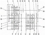
As shown in fig. 1, a 16+16 high-power full-power gear-shifting gearbox comprises a main transmission device, an auxiliary transmission device and a power output device, wherein the input end of the main transmission device is connected with the output shaft of a main clutch, the output end of the main transmission device is connected with the input end of the auxiliary transmission device, and the output end of the auxiliary transmission device is connected with the input end of a rear axle central transmission; the main transmission device is internally provided with a power input shaft S1, a second shaft S2 and a third shaft S3, and the three shafts are arranged in a triangular shape when viewed from the direction of the engine; the auxiliary speed changing device is provided with a four-shaft S4 and a five-shaft S5, wherein the four-shaft S4 is coaxial with a two-shaft S2, and the two shafts are connected through a spline sleeve. In addition, the PTO shaft S6 is coaxial with the power input shaft S1, and the two shafts are connected through a spline sleeve; the twenty-first gear 21 is fixedly connected to the power output shaft S7.
The power input shaft S1 is provided with a first gear 1, a first wet clutch C1, a third gear 3, a second wet clutch C2, a sixth gear 6 and a gear pump power take-off gear 12 from left to right in sequence. The first gear 1 and the gear pump power take-off gear 12 are fixedly connected to the power input shaft S1, the right end face of the first gear 1 is fixedly connected with an external spline, and the friction plate slides on the external spline; the third gear 3 and the sixth gear 6 are sleeved on the power input shaft S1, the left end face of the sixth gear 6 is fixedly connected with an external spline, and the friction plate slides on the external spline; outer hubs of the first wet clutch C1 and the second wet clutch C2 are fixed to left and right ends of the third gear 3, respectively; the electro-hydraulic control gear shifting cylinder respectively controls the first wet clutch C1 to be connected with the first gear 1, and the second wet clutch C2 to be connected with the sixth gear 6.
The second gear 2, the third wet clutch C3, the fourth gear 4, the fourth wet clutch C4, the seventh gear 7, the ninth gear 9 and the tenth gear 10 are sequentially arranged on the second shaft S2 from left to right; the seventh gear 7, the ninth gear 9 and the tenth gear 10 are fixedly connected to a second shaft S2, the left end face of the seventh gear 7 is fixedly connected with an external spline, and the friction plate slides on the external spline; the second gear 2 and the fourth gear 4 are sleeved on the second shaft S2, the right end face of the second gear 2 is fixedly connected with an external spline, and the friction plate slides on the external spline; outer hubs of the third wet clutch C3 and the fourth wet clutch C4 are fixed to left and right ends of the fourth gear 4, respectively; the electro-hydraulic control gear shifting cylinder respectively controls the third wet clutch C3 to be connected with the second gear 2, and the fourth wet clutch C4 to be connected with the seventh gear 7.
A fifth wet clutch C5, a fifth gear 5, a sixth wet clutch C6, an eighth gear 8 and an eleventh gear 11 are sequentially mounted on the three shaft S3 from left to right; the eleventh gear 11 is fixed to the third shaft S3; the fifth gear 5 and the eighth gear 8 are sleeved on the three shafts S3, the left end face of the eighth gear 8 is fixedly connected with an external spline, and the friction plate slides on the external spline; outer hubs of the fifth wet clutch C5 and the sixth wet clutch C6 are fixed to left and right ends of the fifth gear 5, respectively; the electro-hydraulic control shift cylinder controls the sixth wet clutch C6 to be connected with the eighth gear 8.
A thirteenth gear 13, a seventh wet clutch C7, a fifteenth gear 15, an eighth wet clutch C8, a seventeenth gear 17, a nineteenth gear 19 and a second twenty gear 22 are sequentially mounted on the four shaft S4 from left to right, wherein the nineteenth gear 19 and the second twenty gear 22 are duplicate gears; the thirteenth gear 13 is fixedly connected to the four shaft S4, an external spline is fixedly connected to the right end face of the thirteenth gear 13, and the friction plate slides on the external spline; the fifteenth gear 15, the seventeenth gear 17, the nineteenth gear 19 and the twenty-second gear 22 are sleeved on a four-shaft S4, an external spline is fixedly connected to the left end face of the seventeenth gear 17, and friction plates slide on the external spline; the outer hubs of the seventh wet clutch C7 and the eighth wet clutch C8 are welded to the left and right ends of the fifteenth gear 15, respectively; the electro-hydraulic control gear shifting cylinder respectively controls the seventh wet clutch C7 to be connected with the thirteenth gear 13, and the eighth wet clutch C8 to be connected with the seventeenth gear 17.
A fourteenth gear 14, a ninth wet clutch C9, a sixteenth gear 16, a tenth wet clutch C10, an eighteenth gear 18 and a twentieth gear 20 are sequentially mounted on the five shaft S5 from left to right; the eighteenth gear 18 and the twentieth gear 20 are fixedly connected to a five shaft S5, an external spline is fixedly connected to the left end face of the eighteenth gear 18, and a friction plate slides on the external spline; the fourteenth gear 14 and the sixteenth gear 16 are sleeved on a five shaft S5, an external spline is fixedly connected to the right end face of the fourteenth gear 14, and the friction plates slide on the external spline; outer hubs of the ninth wet clutch C9 and the tenth wet clutch C10 are fixed to left and right ends of the sixteenth gear 16, respectively; the electro-hydraulic control gear shifting cylinder respectively controls the ninth wet clutch C9 to be connected with the fourteenth gear 14, and the tenth wet clutch C10 to be connected with the sixteenth gear 16.
The power input shaft S1 transmits power to the PTO shaft S6 through spline connection; the power of each gear passes through the twenty-second twelve gears 22, is meshed through the twenty-first gears 21 and the twenty-second gears 22, and is transmitted to the twenty-first gears 21 which are fixedly connected to the power output shaft S7, and finally is transmitted to the power output shaft S7.
The gear shifting principle of the utility model is as follows:
the full-power gear shifting device can realize two gear shifting modes of forward and backward:
in the main transmission, the first wet clutch C1, the second wet clutch C2, the third wet clutch C3 and the fourth wet clutch C4 can form four forward gears, i.e., a forward first gear, a forward second gear, a forward third gear and a forward fourth gear; the first wet clutch C1, the third wet clutch C3, the fifth wet clutch C5 and the sixth wet clutch C6 can form four reverse gears, i.e., a reverse first gear, a reverse second gear, a reverse third gear and a reverse fourth gear; the power transmission route of each gear will be explained below.
In forward first gear, the second wet clutch C2 and the third wet clutch C3 are engaged, the first wet clutch C1 and the fourth wet clutch C4 are disengaged, and power is input from the power input shaft S1 → the first gear 1 → the second gear 2 → the third wet clutch C3 → the fourth gear 4 → the third gear 3 → the second wet clutch C2 → the sixth gear 6 → the ninth gear 9 → the second shaft S2 → the fourth shaft S4.
In the forward second gear, the first wet clutch C1 and the second wet clutch C2 are engaged, the third wet clutch C3 and the fourth wet clutch C4 are disengaged, and power is input from the power input shaft S1 → the first wet clutch C1 → the second wet clutch C2 → the sixth gear 6 → the ninth gear 9 → the second shaft S2 → the four shaft S4.
In the third forward gear, the third wet clutch C3 and the fourth wet clutch C4 are engaged, the first wet clutch C1 and the second wet clutch C2 are disengaged, and power is input from the power input shaft S1 → the first gear 1 → the second gear 2 → the third wet clutch C3 → the fourth wet clutch C4 → the second shaft S2 → the four shaft S4.
In the fourth forward gear, the first clutch C1 and the fourth clutch C4 are engaged, the second wet clutch C2 and the third wet clutch C3 are disengaged, and power is input from the power input shaft S1 → the first wet clutch C1 → the third gear 3 → the fourth gear 4 → the fourth wet clutch C4 → the second shaft S2 → the fourth shaft S4.
In the reverse first gear, the third wet clutch C3 and the fifth wet clutch C5 are engaged, the first wet clutch C1 and the sixth wet clutch C6 are disengaged, and power is input from the power input shaft S1 → the first gear 1 → the second gear 2 → the third wet clutch C3 → the fourth gear 4 → the third gear 3 → the fifth gear 5 → the fifth wet clutch C5 → the third shaft 3 → the eleventh gear 11 → the tenth gear 10 → the second shaft S2 → the fourth shaft S4.
In the reverse second gear, the first wet clutch C1 and the fifth wet clutch C5 are engaged, the second wet clutch C2 and the sixth wet clutch C6 are disengaged, and power is input from the power input shaft S1 → the first wet clutch C1 → the third gear 3 → the fifth gear 5 → the fifth wet clutch C5 → the third shaft 3 → the eleventh gear 11 → the tenth gear 10 → the second shaft S2 → the fourth shaft S4.
In the third reverse gear, the third wet clutch C3 and the sixth wet clutch C6 are engaged, the first wet clutch C1 and the fifth wet clutch C5 are disengaged, and power is input from the power input shaft S1 → the first gear 1 → the second gear 2 → the third wet clutch C3 → the fourth gear 4 → the third gear 3 → the fifth gear 5 → the sixth wet clutch C6 → the eighth gear 8 → the seventh gear 7 → the second shaft S2 → the fourth shaft S4.
In the fourth reverse gear, the first wet clutch C1 and the sixth wet clutch C6 are engaged, the third wet clutch C3 and the fifth wet clutch C5 are disengaged, and power is input from the power input shaft S1 → the first wet clutch C1 → the third gear 3 → the fifth gear 5 → the sixth wet clutch C6 → the eighth gear 8 → the seventh gear 7 → the second shaft S2 → the fourth shaft S4.
In the sub-transmission, the seventh wet clutch C7, the eighth wet clutch C8, the ninth wet clutch C9, and the tenth wet clutch C10 can form four range gears, i.e., an LL gear, an L gear, an H gear, and an HH gear, and the rotation speed is sequentially increased. The power transmission route of each gear will be explained below.
In LL gear, the eighth wet clutch C8 and the ninth wet clutch C9 are engaged, the seventh wet clutch C7 and the tenth wet clutch C10 are disengaged, and power is transmitted from the four shaft S4 → the thirteenth gear 13 → the fourteenth gear 14 → the ninth wet clutch C9 → the sixteenth gear 16 → the fifteenth gear 15 → the eighth wet clutch C8 → the seventeenth gear 17 → the eighteenth gear 18 → the five shaft S5 → the twentieth gear 20 → the nineteenth gear 19 → the second twenty gear 22 → the twenty-first gear 21 → the power output shaft S7.
In the L range, the ninth wet clutch C9 and the tenth wet clutch C10 are engaged, the seventh wet clutch C7 and the eighth wet clutch C8 are disengaged, and power is transmitted from the four shaft S4 → the thirteenth gear 13 → the fourteenth gear 14 → the ninth wet clutch C9 → the tenth wet clutch C10 → the five shaft S5 → the twentieth gear 20 → the nineteenth gear 19 → the second gear 22 → the twenty-first gear 21 → the power output shaft S7.
In the H range, the seventh wet clutch C7 and the eighth wet clutch C8 are engaged, the ninth wet clutch C9 and the tenth wet clutch C10 are disengaged, and power is transmitted from the four shaft S4 → the seventh wet clutch C7 → the eighth wet clutch C8 → the seventeenth gear 17 → the eighteenth gear 18 → the five shaft S5 → the twentieth gear 20 → the nineteenth gear 19 → the second gear 22 → the twenty-first gear 21 → the power output shaft S7.
In HH gear, the seventh wet clutch C7 and the tenth wet clutch C10 are engaged, the eighth wet clutch C8 and the ninth wet clutch C9 are disengaged, and power is transmitted from the four shaft S4 → the seventh wet clutch C7 → the fifteenth gear 15 → the sixteenth gear 16 → the tenth wet clutch C10 → the five shaft S5 → the twentieth gear 20 → the nineteenth gear 19 → the second twenty gear 22 → the twenty-first gear 21 → the power take-off shaft S7.
After the power reaches the power output shaft S7, the power is finally transmitted to the central transmission input end of the rear axle.
In a word, the full-power gear shifting gearbox forms 16 forward gears and 16 backward gears through fewer gear combinations, the structure is compact, the cost is saved, the gear shifting time is short, and the operation efficiency is greatly improved.