CN216760181U - Numerical control cutting machine with tool changing function - Google Patents
Numerical control cutting machine with tool changing function Download PDFInfo
- Publication number
- CN216760181U CN216760181U CN202122730914.1U CN202122730914U CN216760181U CN 216760181 U CN216760181 U CN 216760181U CN 202122730914 U CN202122730914 U CN 202122730914U CN 216760181 U CN216760181 U CN 216760181U
- Authority
- CN
- China
- Prior art keywords
- dust collection
- driving
- axis
- replaceable
- tool
- Prior art date
- Legal status (The legal status is an assumption and is not a legal conclusion. Google has not performed a legal analysis and makes no representation as to the accuracy of the status listed.)
- Active
Links
- 238000005520 cutting process Methods 0.000 title claims abstract description 17
- 238000003801 milling Methods 0.000 claims abstract description 40
- 210000000078 claw Anatomy 0.000 claims abstract description 21
- 239000000428 dust Substances 0.000 claims description 98
- 239000000463 material Substances 0.000 claims description 29
- 230000006835 compression Effects 0.000 claims description 15
- 238000007906 compression Methods 0.000 claims description 15
- 238000013519 translation Methods 0.000 claims description 9
- 238000007599 discharging Methods 0.000 claims description 8
- 230000007246 mechanism Effects 0.000 claims description 7
- 238000006073 displacement reaction Methods 0.000 claims description 5
- 238000012545 processing Methods 0.000 abstract description 20
- 238000000034 method Methods 0.000 description 7
- 230000008569 process Effects 0.000 description 7
- 230000000694 effects Effects 0.000 description 5
- 238000003754 machining Methods 0.000 description 5
- 238000013461 design Methods 0.000 description 4
- 230000007704 transition Effects 0.000 description 3
- 230000008859 change Effects 0.000 description 2
- 230000005611 electricity Effects 0.000 description 2
- 238000012986 modification Methods 0.000 description 2
- 230000004048 modification Effects 0.000 description 2
- 230000009286 beneficial effect Effects 0.000 description 1
- 239000002131 composite material Substances 0.000 description 1
- 230000007547 defect Effects 0.000 description 1
- 238000010586 diagram Methods 0.000 description 1
- 238000004519 manufacturing process Methods 0.000 description 1
- 238000003825 pressing Methods 0.000 description 1
- 238000011160 research Methods 0.000 description 1
- 230000002441 reversible effect Effects 0.000 description 1
- 239000002023 wood Substances 0.000 description 1
Images




Landscapes
- Auxiliary Devices For Machine Tools (AREA)
Abstract
The utility model relates to a numerical control cutting machine with a replaceable cutter, which comprises a rack, a central control platform, an X axial driving device, a milling cutter device with a replaceable cutter head, a cross beam device and a first Y axial driving device, wherein the central control platform is arranged on the rack; the milling cutter device with the replaceable cutter head comprises a first cutter head, an electric spindle, a replaceable cutter library device and a first Z-axis driving device, wherein the X-axis driving device is connected with the first Z-axis driving device in a driving mode and moves in a reciprocating mode along the X-axis direction, so that the electric spindle and the first cutter head both move in a reciprocating mode along the X-axis direction; the replaceable tool magazine device comprises a plurality of second tool bits detachably connected with the electric spindle, a frame and a second Y-axis driving device, wherein a plurality of clamping claws are arranged on the tool rest side by side, the second tool bits are clamped on the clamping claws, the number of the second tool bits is smaller than that of the clamping claws, and the electric spindle can be selectively connected with the first tool bits or the second tool bits; compared with the traditional rotating disc type tool changing, the tool changing device saves the stroke of the tool bit to be changed, greatly improves the tool changing efficiency, then improves the subsequent processing efficiency and reduces the processing cost.
Description
Technical Field
The utility model relates to the technical field of wood processing, in particular to a cutter-replaceable numerical control cutting machine.
Background
The existing carving and cutting single machine can not meet the requirement of composite processing, especially in the production process of molded door plates and office furniture, because of the increase of the modeling complexity of the office furniture, a plurality of knife shapes need to be added, and one whole plate can often be simultaneously selected from 6 to 8 knives for processing during processing. The existing general adoption carousel formula tool changing, it all needs the carousel to rotate earlier to the idle position usually when the tool changing at every turn, and the electricity main shaft moves to the idle position again and unloads the sword, then the carousel rotates to the corresponding tool bit position of waiting to change again, and the electricity main shaft moves the tool bit position tool changing of waiting to change at last, and whole tool changing process is complicated, leads to the tool changing required time long, influences machining efficiency and processing cost then.
Therefore, in the patent application of the utility model, the applicant elaborately researches a numerical control cutting machine capable of changing a cutter to solve the problems.
SUMMERY OF THE UTILITY MODEL
Aiming at the defects of the prior art, the utility model mainly aims to provide the numerical control cutting machine capable of changing the cutter, which saves the stroke of the cutter head to be changed compared with the traditional rotating disc type cutter changing, greatly improves the cutter changing efficiency, improves the subsequent processing efficiency and reduces the processing cost.
In order to achieve the purpose, the utility model adopts the following technical scheme:
a numerical control cutting machine with replaceable cutters comprises a rack, a center console, an X-axis driving device, a milling cutter device with replaceable cutters, a beam device which is positioned above the rack and stretches across the rack along the X-axis direction, and a first Y-axis driving device which is used for driving the beam device to reciprocate along the Y-axis direction;
the milling cutter device with the replaceable cutter head is arranged on the cross beam device, the X-axis driving device drives the milling cutter device connected with the replaceable cutter head to enable the milling cutter device with the replaceable cutter head to reciprocate along the X-axis direction, the rack is provided with a working table, and the milling cutter device with the replaceable cutter head moves in the working table;
the milling cutter device with the replaceable cutter head comprises a first cutter head, an electric spindle detachably connected with the first cutter head, a replaceable cutter library device positioned below the electric spindle and a first Z-axis driving device used for driving the electric spindle to reciprocate along the Z-axis direction, wherein the X-axis driving device is connected with the first Z-axis driving device in a driving mode and reciprocates along the X-axis direction so that the electric spindle and the first cutter head can reciprocate along the X-axis direction;
the replaceable tool magazine device comprises a plurality of second tool bits detachably connected with the electric spindle, a tool rest extending along the X-axis direction and a second Y-axis driving device used for driving the tool rest to reciprocate along the Y-axis direction, a plurality of clamping claws are arranged on the tool rest side by side along the X-axis direction, the second tool bits are clamped on the clamping claws, the number of the second tool bits is smaller than that of the clamping claws, and the electric spindle can be selectively connected with the first tool bits or the second tool bits;
the center console is electrically connected with the X-axis driving device, the first Y-axis driving device, the second Y-axis driving device, the electric spindle and the first Z-axis driving device respectively.
Preferably, the milling cutter device with the replaceable cutter head is provided with a first dust suction device, the first dust suction device comprises a first dust suction cover, a second Z-axis driving device arranged on the electric spindle and a dust collection unit communicated with the first dust suction cover, and the second Z-axis driving device is connected with the first dust suction cover in a driving mode and moves back and forth along the Z-axis direction, so that the first dust suction cover can cover or expose the first cutter head.
As a preferable scheme, a dust collection box and a second dust collection device for discharging and dedusting are arranged on the cross beam device, the second dust collection device comprises a second dust collection cover and an inclined push cylinder for driving the second dust collection cover to lift, and a dust collection outlet of the second dust collection cover is communicated with the dust collection unit through the dust collection box.
As a preferable scheme, the dust collecting unit includes a dust collecting three-way joint, a dust collecting pipe and an L-shaped bracket for fixing the dust collecting pipe, the dust collecting three-way joint includes a first joint, a second joint and a third joint respectively communicated with the first joint and the second joint, the first joint is communicated with a dust collecting outlet of the first dust collecting hood through a first pipeline, the second joint is communicated with the dust collecting box through a second pipeline, the third joint is communicated with the dust collecting pipe, and the L-shaped bracket is disposed on the beam device.
As a preferable scheme, the second Y-axis driving device includes a Y-axis translational sliding seat and a Y-axis translational driving mechanism for driving the Y-axis translational sliding seat to move along the Y-axis, the tool holder is disposed on the Y-axis translational sliding seat, the cross beam device is provided with a Y-axis auxiliary sliding rail, and the Y-axis translational sliding seat is mounted along the Y-axis auxiliary sliding rail in a reciprocating displacement manner.
As a preferable scheme, the beam device is provided with a material suction device for feeding and discharging and a side positioning device for side positioning, the material suction device and the side positioning device move in the Y-axis direction in the workbench surface along with the movement of the beam device, and the central control console is electrically connected to the material suction device and the side positioning device respectively.
As a preferred scheme, inhale the material device including the sucking disc, install bracing piece on the beam device and be used for driving sucking disc material lift cylinder of inhaling that goes up and down, the bracing piece extends the setting along the Y axial, inhale material lift cylinder and install on the extension tip of bracing piece, sucking disc and the milling cutter device of interchangeable tool bit are located the opposite side of beam device respectively.
As a preferred scheme, the device also comprises a compression roller device, wherein the compression roller device comprises a compression roller bracket and driving cylinders for driving the compression roller bracket to lift together, and the driving cylinders are arranged on two sides of the rack along the Y-axis direction.
Compared with the prior art, the utility model has obvious advantages and beneficial effects, particularly:
the cutter head needs to be replaced mainly through the matching of a milling cutter device with replaceable cutter heads and an X axial driving device, an electric main shaft is driven to move to the front of an empty clamping claw through the X axial driving device and a first Z axial driving device respectively, a cutter frame is driven to move forwards through a second Y axial driving device, the clamping claw and a second cutter head are arranged on the cutter frame side by side along the X axial direction, the clamping claw and the second cutter head can move forwards while the cutter frame moves, the original cutter head (a first cutter head) is clamped at the moment, then the electric main shaft is reset and then moves to the position of the cutter head (a second cutter head) to be replaced to realize replacement, the cutter frame only needs to move in the whole replacement process, the travel of the cutter replacement is realized through the movement of the electric main shaft, compared with the traditional rotary disc type cutter replacement, the travel of the cutter head to be replaced is saved, and the cutter replacing efficiency is greatly improved, the subsequent processing efficiency is improved, and the processing cost is reduced;
secondly, through the design of the first dust suction device, dust generated in the routing process can be adsorbed, and through the matching of the second dust suction device, dust existing after the machining is finished can be adsorbed, so that the dust suction effect generated in the machining process is effectively improved, and a certain environment protection effect is achieved;
and through the design of the material suction device, automatic feeding and discharging are realized, the processing efficiency is improved, the cooperation of the side positioning device and the compression roller device is assisted, the stability and the reliability of the workpiece to be processed in the processing process are ensured, and the processing quality is further improved.
To more clearly illustrate the structural features and effects of the present invention, the following detailed description is given with reference to the accompanying drawings and specific embodiments.
Drawings
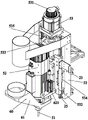
FIG. 1 is a perspective assembly structure of the preferred embodiment of the present invention;
FIG. 2 is a schematic view of another angle assembly structure according to the preferred embodiment of the present invention;
FIG. 3 is an enlarged schematic view of the structure at A in FIG. 2;
FIG. 4 is an enlarged view of the structure at B in FIG. 2;
FIG. 5 is a schematic view of a portion of a milling cutter device with replaceable cutting heads according to a preferred embodiment of the present invention (the replaceable magazine device is not shown);
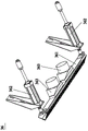
FIG. 6 is a schematic view of the replaceable magazine tool of the preferred embodiment of the present invention (showing the first tool bit);
FIG. 7 is a schematic structural view of a second vacuum cleaner according to a preferred embodiment of the present invention;
FIG. 8 is a schematic diagram of a rear positioning cylinder according to a preferred embodiment of the present invention.
The reference numbers illustrate:
10. frame 11, table top
12. Second rack 13, Y axial slide rail
20. X-axis driving device
21. First driving motor 22 and first mounting plate
23. X-axis slider 24 and first gear
25. Z-axis sliding rail
30. Cross beam device
31. Crossbeam 32, first stand
33. Second upright column 34 and first rack
35. X-axis sliding rail 36 and second dust suction device
361. Second dust hood 362 and oblique push cylinder
363. Auxiliary direction sliding rail for transitional dust collection shell 37 and Y axis
40. First Y-axis driving device
41. Second drive motor 42, third mounting plate
43. Y-axis sliding block
51. First tool bit 52 and electric spindle
53. First Z-axis driving device
531. Z-axis driving motor 532 and second mounting plate
533. First Z-axis slide block 534 and second Z-axis slide block
535. Screw mandrel
54. Replaceable tool magazine device
541. First gripper jaw 542 and second gripper jaw
543. Second tool bit 544, tool holder
56. Second Y-axis driving device
561. Y-axis translation sliding seat 562 and Y-axis translation driving mechanism
60. First dust-absorbing device
61. First dust hood 62 and second Z-axis driving device
621. Z-axis cylinder
63. Dust collecting unit 631 and dust collecting tee joint
6311. First joint 6312, second joint
6313. Third joint
632. Fixing ring 633, L-shaped bracket
64. Milling cutter protection cover 641, preceding curb plate
70. Material sucking device
71. Suction cup 72 and support rod
73. Material sucking lifting cylinder
81. Side positioning device 82 and press roller device
821. Compression roller support 822 and driving cylinder
83. Rear positioning device 831 and rear positioning cylinder
832. Lifting driving cylinder
91. Center console
911. Display screen 912 and universal caster
913. A support plate 92 and a fixed electric box.
Detailed Description
The utility model is further described with reference to the following detailed description and accompanying drawings.
As shown in fig. 1 to 8, a numerical control cutting machine with replaceable cutter comprises a rack 10, a center console 91, an X-axis driving device 20, a milling cutter device with replaceable cutter head, a beam device 30 located above the rack 10 and crossing the rack 10 along the X-axis direction, and a first Y-axis driving device 40 for driving the beam device 30 to reciprocate along the Y-axis direction; the X-axis direction means the left-right direction, the Y-axis direction means the front-rear direction, and the Z-axis direction means the up-down direction.
The milling cutter device with the replaceable cutter head is arranged on the beam device 30, the X-axis driving device 20 is connected with the milling cutter device with the replaceable cutter head in a driving mode so that the milling cutter device with the replaceable cutter head can reciprocate on the beam device 30 along the X-axis direction, the rack 10 is provided with a working table surface 11, and the milling cutter device with the replaceable cutter head moves in the working table surface 11;
in this embodiment, the X-axis driving device 20 includes a first driving motor 21, a first mounting plate 22, an X-axis slider 23, and a first gear 24, the milling cutter device with replaceable cutter head and the first driving motor 21 are both mounted on the first mounting plate 22, the first mounting plate 22 is mounted on the X-axis slider 23, the first gear 24 is mounted on an output shaft of the first driving motor 21, a first rack 34 and an X-axis slide rail 35 extending along the X-axis direction are mounted on a cross beam 31 of a cross beam device 30, the X-axis slider 23 is mounted along the X-axis slide rail 35 in a reciprocating displacement manner, and the milling cutter device with replaceable cutter head is slidably connected along the X-axis direction by meshing the first gear 24 with the corresponding first rack 34.
The milling cutter device with the replaceable cutter head comprises a first cutter head 51, an electric spindle 52 detachably connected to the first cutter head 51, a replaceable cutter library device 54 positioned below the electric spindle 52 and a first Z-axis driving device 53 for driving the electric spindle 52 to reciprocate along the Z-axis direction, wherein the X-axis driving device 20 is connected with the first Z-axis driving device 53 in a driving manner and reciprocates along the X-axis direction so that the electric spindle 52 and the first cutter head 51 both reciprocate along the X-axis direction;
in this embodiment, the first Z-axis driving device 53 includes a Z-axis driving motor 531, a second mounting plate 532, a first Z-axis sliding block 533, a second Z-axis sliding block 534, and a screw rod 535 extending along the Z-axis direction, and the first mounting plate 22 of the X-axis driving device 20 is provided with a Z-axis sliding rail 25 extending along the Z-axis direction;
the Z-axis driving motor 531 is disposed on the first mounting plate 22, the lead screw 535 is driven by the Z-axis driving motor 531, the first Z-axis sliding block 533 is adapted to the lead screw 535 and reciprocally slidably disposed along the lead screw 535, the electric spindle 52 is disposed on the second mounting plate 532, the second mounting plate 532 is mounted on the first Z-axis sliding block 533 so that the electric spindle 52 reciprocally slides along the lead screw 535 with the first Z-axis sliding block 533, the second Z-axis sliding block 534 is reciprocally movably mounted along the Z-axis sliding rail 25, and the second mounting plate 532 is mounted on the second Z-axis sliding block 534.
The replaceable tool magazine device 54 comprises a plurality of second tool bits 543 detachably connected to the electric spindle 52, tool rests 544 extending along the X-axis direction, and a second Y-axis driving device 56 for driving the tool rests 544 to reciprocate along the Y-axis direction, wherein a plurality of clamping claws are arranged on the tool rests 544 in parallel along the X-axis direction, the second tool bits 543 are clamped on the clamping claws, the number of the second tool bits 543 is smaller than that of the clamping claws, and the electric spindle 52 can be selectively connected with the first tool bits 51 or the second tool bits 543; the center console 91 is electrically connected to the X-axis driving device 20, the first Y-axis driving device 40, the second Y-axis driving device 56, the motorized spindle 52, and the first Z-axis driving device 53, respectively.
In this embodiment, the number of the clamping claws is 12, and 11 second tips 543 are provided. Of the 12 clamping jaws, any 11 clamping jaws are defined as 11 first clamping jaws 541, the other one is defined as a second clamping jaw 542, each first clamping jaw 541 is provided with a second tool bit 543, and the second clamping jaw 542 is empty. Next, the operation principle of the tool changer will be roughly described by taking the example in which the first tool bit 51 is connected to the electric spindle 52:
1. the X-axis driving device 20 drives the electric spindle 52 to move to a position right above the front side of the second clamping jaw 542;
2. the first Z-axis driving device 53 drives the electric spindle 52 to move downwards until the first tool bit 51 is positioned right in front of the second clamping jaw 542;
3. the second Y-axis driving device 56 drives the tool post 544 to drive the second clamping jaw 542 to move forward until the second clamping jaw 542 is matched with the first tool bit 51 (the two can be in snap fit), and at this time, the first Z-axis driving device 53 drives the electric spindle 52 to move upward until the electric spindle 52 is completely separated from the first tool bit 51, so as to complete the detachment of the first tool bit 51;
4. the X-axis driving device 20 drives the electric spindle 52 to move to a position right above the first clamping claw 541 to be replaced;
5. the first Z-axis driving device 53 drives the electric spindle 52 to move downward until the second tool tip 543 and the electric spindle 52 are connected, and at this time, the second Y-axis driving device 56 drives the tool post 544 to move backward until the replaced second tool tip 543 is completely separated from the corresponding first clamping claw 541, so that the replacement of the second tool tip 543 is completed.
The milling cutter device for the replaceable cutter head is provided with a first dust suction device 60, the first dust suction device 60 comprises a first dust suction cover 61, a second Z-axis driving device 62 arranged on the electric spindle 52 and a dust collection unit communicated with the first dust suction cover 61, and the second Z-axis driving device 62 is in driving connection with the first dust suction cover 61 to move back and forth along the Z-axis direction so that the first dust suction cover 61 can cover or expose the first cutter head 51. Preferably, the second Z-axis driving device 62 includes a Z-axis cylinder 621. The cross beam device 30 is provided with a dust collection box 38 and a second dust collection device 36 for discharging and dedusting, the second dust collection device 36 comprises a second dust collection cover 361 and an inclined push cylinder 362 for driving the second dust collection cover 361 to ascend and descend, and a dust collection outlet of the second dust collection cover 361 is communicated with a dust collection unit through the dust collection box 38. In this embodiment, the second dust collection cover 361 is connected with a transition dust collection housing 363, the transition dust collection housing 363 is communicated with the second dust collection cover 361, and a dust collection outlet of the transition dust collection housing 363 is communicated with the dust collection box 38.
The dust collection unit comprises a dust collection three-way joint 631, a dust collection pipe and an L-shaped support 633 for fixing the dust collection pipe, wherein the dust collection three-way joint 631 comprises a first joint 6311, a second joint 6312 and a third joint 6313 which is respectively communicated with the first joint 6311 and the second joint 6312, the first joint 6311 is communicated with a dust collection outlet of the first dust collection cover 61 through a first pipeline, the second joint 6312 is communicated with the dust collection box 38 through a second pipeline, the third joint 6313 is communicated with the dust collection pipe, the L-shaped support 633 is arranged on the beam device 30, and a fixing ring 632 is arranged on the L-shaped support 633 along the extending direction of the L-shaped support.
The milling cutter device aiming at the replaceable cutter head is also provided with a milling cutter protection cover 64, the milling cutter protection cover 64 is covered on the periphery of the electric spindle 52 and the first cutter head 51 thereof, and the upper end and the lower end of the milling cutter protection cover 64 are open. The milling cutter protection cover 64 has a front side plate 641, and the front side plate 641 is a reversible front side plate 641. Preferably, the router bit guard 64 is disposed on the second mounting plate 532.
The second Y-axis driving device 56 includes a Y-axis translational sliding seat 561 and a Y-axis translational driving mechanism 562 for driving the Y-axis translational sliding seat 561 to move along the Y-axis, the Y-axis translational driving mechanism 562 is installed on the cross beam device 30, the tool holder 544 is arranged on the Y-axis translational sliding seat 561, the cross beam device 30 is provided with a Y-axis auxiliary sliding rail 37, and the Y-axis translational sliding seat 561 is installed along the Y-axis auxiliary sliding rail 37 in a reciprocating displacement manner. Preferably, the Y-axis translation drive mechanism 562 is a Y-axis drive cylinder 822.
The cross beam device 30 is provided with a material suction device 70 for feeding and discharging and a side positioning device 81 for side positioning, the material suction device 70 and the side positioning device 81 both move along the Y-axis direction in the workbench surface 11 along with the movement of the cross beam device 30, the central control console 91 is electrically connected to the material suction device 70 and the side positioning device 81 respectively, and preferably, the side positioning device 81 comprises a side material pushing cylinder.
The device further comprises a compression roller device 82, a rear positioning device 83 and a fixed electric box 92 for supplying power, wherein the compression roller device 82 comprises a compression roller bracket 821 and a driving cylinder 822 for driving the compression roller bracket 821 to ascend and descend together, and the driving cylinder 822 is installed on two sides of the frame 10 along the Y-axis direction. The roll holder 821 spans across the work table 11.
The rear positioning device 83 is disposed on the beam device 30, the rear positioning device 83 includes a rear positioning cylinder 831 for pushing material behind and a lifting driving cylinder 832 for driving the rear positioning cylinder 831 to lift, and the lifting driving cylinder 832 is disposed on the beam device 30. In the present embodiment, the cross beam device 30 includes a cross beam 31 extending along the X-axis direction, and a first column 32 and a second column 33 respectively located at the left end and the right end of the cross beam 31, and the milling cutter device with replaceable cutter head, the L-shaped bracket 633 and the material suction device 70 are disposed on the cross beam 31, and of course, there are corresponding devices disposed on the cross beam 31, which are not listed here. The Y-axis translation drive mechanisms 562 are disposed on respective uprights.
In this embodiment, the first Y-axis driving device 40 includes a second driving motor 41, a third mounting plate 42, a Y-axis slider 43, and a second gear (not shown in the figure), the first upright column 32 and the second driving motor 41 are both mounted on the third mounting plate 42, the third mounting plate 42 is mounted on the Y-axis slider 43, the second gear is mounted on an output shaft of the second driving motor 41, a second rack 12 extending along the Y-axis direction and a Y-axis slide rail 13 are mounted on a side surface of the rack 10 corresponding to the first upright column 32, the Y-axis slider 43 is mounted in a reciprocating displacement manner along the Y-axis slide rail 13, and the cross beam device 30 is engaged with the corresponding second rack 12 through the second gear and is connected in a sliding manner along the Y-axis direction. The center console 91 is a movable console, and a display screen 911, a universal caster 912 and a supporting plate 913 for bearing a keyboard and a mouse are arranged on the movable console. Through the movable operation platform, the use convenience is provided.
The following working principle is explained in general:
placing a plate to be processed on an external lifting table, driving the beam device 30 to move through the first Y-axis driving device 40, adsorbing one end of the plate to be processed by the sucker 71 of the material sucking device 70 on the beam device 30, and dragging the plate to be processed to move to the working table surface 11;
when the plate to be processed is moved to a working position, the plate to be processed is firstly positioned through the matching of the rear positioning device 83 and the side positioning device 81, then the plate to be processed is fixed through the downward pressing of the press roller device 82, and then the plate to be processed can be processed (shaped, punched and cut) through the milling cutter device with the replaceable cutter head; after the processing is finished, the positioning and the fixing are released, and then the material is discharged by the material suction device 70.
The utility model is characterized in that the cutter head is required to be replaced mainly through the matching of a milling cutter device with a replaceable cutter head and an X-axis driving device, an electric spindle is driven to move to the front of an empty clamping claw through the X-axis driving device and a first Z-axis driving device respectively, a cutter frame is driven to move forwards through a second Y-axis driving device, the clamping claw and a second cutter head are arranged on the cutter frame side by side along the X-axis direction, the clamping claw and the second cutter head can move forwards while the cutter frame moves, the original cutter head (a first cutter head) is clamped, then the electric spindle is reset and then moves to the cutter head (a second cutter head) to be replaced, the cutter frame only needs to move in the whole replacing process, the cutter replacing stroke is realized through the movement of the electric spindle, and compared with the traditional rotary disc type cutter replacing, the stroke of the cutter head to be replaced is saved, the tool changing efficiency is greatly improved, the subsequent processing efficiency is improved, and the processing cost is reduced;
secondly, through the design of the first dust suction device, dust generated in the routing process can be adsorbed, and through the matching of the second dust suction device, dust existing after the machining is finished can be adsorbed, so that the dust suction effect generated in the machining process is effectively improved, and a certain environment protection effect is achieved;
and through the design of the material suction device, automatic feeding and discharging are realized, the processing efficiency is improved, the cooperation of the side positioning device and the compression roller device is assisted, the stability and the reliability of a workpiece to be processed in the processing process are ensured, and the processing quality is further improved.
The above description is only a preferred embodiment of the present invention, and is not intended to limit the technical scope of the present invention, so that any minor modifications, equivalent changes and modifications made to the above embodiment according to the technical spirit of the present invention are within the technical scope of the present invention.
Claims (8)
1. The utility model provides a material machine is driven in numerical control of interchangeable sword which characterized in that: the milling cutter comprises a rack, a center console, an X-axis driving device, a milling cutter device with replaceable cutter heads, a beam device which is positioned above the rack and crosses the rack along the X-axis direction, and a first Y-axis driving device which is used for driving the beam device to reciprocate along the Y-axis direction;
the milling cutter device with the replaceable cutter head is arranged on the cross beam device, the X-axis driving device drives the milling cutter device connected with the replaceable cutter head to enable the milling cutter device with the replaceable cutter head to reciprocate along the X-axis direction, the rack is provided with a working table, and the milling cutter device with the replaceable cutter head moves in the working table;
the milling cutter device with the replaceable cutter head comprises a first cutter head, an electric spindle detachably connected with the first cutter head, a replaceable cutter library device positioned below the electric spindle and a first Z-axis driving device used for driving the electric spindle to reciprocate along the Z-axis direction, wherein the X-axis driving device is connected with the first Z-axis driving device in a driving mode and reciprocates along the X-axis direction so that the electric spindle and the first cutter head can reciprocate along the X-axis direction;
the replaceable tool magazine device comprises a plurality of second tool bits detachably connected with the electric spindle, a tool rest extending along the X-axis direction and a second Y-axis driving device used for driving the tool rest to reciprocate along the Y-axis direction, a plurality of clamping claws are arranged on the tool rest side by side along the X-axis direction, the second tool bits are clamped on the clamping claws, the number of the second tool bits is smaller than that of the clamping claws, and the electric spindle can be selectively connected with the first tool bits or the second tool bits;
the center console is respectively and electrically connected with the X axial driving device, the first Y axial driving device, the second Y axial driving device, the electric spindle and the first Z axial driving device.
2. The numerical control cutting machine with the replaceable cutter according to claim 1, characterized in that: the milling cutter device aiming at the replaceable cutter head is provided with a first dust suction device, the first dust suction device comprises a first dust suction cover, a second Z-axis driving device arranged on the electric spindle and a dust collection unit communicated with the first dust suction cover, and the second Z-axis driving device is connected with the first dust suction cover in a driving mode and reciprocates along the Z-axis direction so that the first dust suction cover can cover or expose the first cutter head.
3. The numerical control cutting machine with the replaceable cutter according to claim 2, characterized in that: the beam device is provided with a dust collection box and a second dust collection device for discharging and dedusting, the second dust collection device comprises a second dust collection cover and an inclined push cylinder for driving the second dust collection cover to lift, and a dust collection outlet of the second dust collection cover is communicated with the dust collection unit through the dust collection box.
4. The tool-replaceable numerical control cutting machine according to claim 3, characterized in that: the dust collection unit comprises a dust collection three-way joint, a dust collection pipe and an L-shaped support used for fixing the dust collection pipe, wherein the dust collection three-way joint is provided with a first joint, a second joint and a third joint which is respectively communicated with the first joint and the second joint, the first joint is communicated with a dust collection outlet of the first dust collection cover through a first pipeline, the second joint is communicated with a dust collection box through a second pipeline, the third joint is communicated with the dust collection pipe, and the L-shaped support is arranged on the beam device.
5. The numerical control cutting machine with the replaceable cutter according to claim 1, characterized in that: the second Y axial driving device comprises a Y axial translation sliding seat and a Y axial translation driving mechanism used for driving the Y axial translation sliding seat to move along the Y axial direction, the tool rest is arranged on the Y axial translation sliding seat, a Y axial auxiliary sliding rail is arranged on the cross beam device, and the Y axial translation sliding seat is arranged along the Y axial auxiliary sliding rail in a reciprocating displacement mode.
6. The numerical control cutting machine with the replaceable cutter according to claim 1, characterized in that: the cross beam device is provided with a material suction device for feeding and discharging and a side positioning device for side positioning, the material suction device and the side positioning device move in the Y-axis direction in the workbench surface along with the movement of the cross beam device, and the central control console is electrically connected with the material suction device and the side positioning device respectively.
7. The numerical control cutting machine with the replaceable knife according to claim 6, characterized in that: inhale the material device including the sucking disc, install bracing piece on the beam device and be used for driving sucking disc go up and down inhale material lift cylinder, the bracing piece extends the setting along the Y axial, inhale material lift cylinder and install on the extension tip of bracing piece, the milling cutter device of sucking disc and interchangeable tool bit is located the opposite side of beam device respectively.
8. The tool-replaceable numerical control cutting machine according to claim 7, characterized in that: the device is characterized by further comprising a compression roller device, wherein the compression roller device comprises a compression roller support and driving cylinders used for driving the compression roller support to lift together, and the driving cylinders are mounted on two sides of the rack in the Y-axis direction.
Priority Applications (1)
| Application Number | Priority Date | Filing Date | Title |
|---|---|---|---|
| CN202122730914.1U CN216760181U (en) | 2021-11-09 | 2021-11-09 | Numerical control cutting machine with tool changing function |
Applications Claiming Priority (1)
| Application Number | Priority Date | Filing Date | Title |
|---|---|---|---|
| CN202122730914.1U CN216760181U (en) | 2021-11-09 | 2021-11-09 | Numerical control cutting machine with tool changing function |
Publications (1)
| Publication Number | Publication Date |
|---|---|
| CN216760181U true CN216760181U (en) | 2022-06-17 |
Family
ID=81960729
Family Applications (1)
| Application Number | Title | Priority Date | Filing Date |
|---|---|---|---|
| CN202122730914.1U Active CN216760181U (en) | 2021-11-09 | 2021-11-09 | Numerical control cutting machine with tool changing function |
Country Status (1)
| Country | Link |
|---|---|
| CN (1) | CN216760181U (en) |
-
2021
- 2021-11-09 CN CN202122730914.1U patent/CN216760181U/en active Active
Similar Documents
| Publication | Publication Date | Title |
|---|---|---|
| CN112620811A (en) | Small-sized round piece precision chamfering machine with waste cleaning function | |
| CN111730695A (en) | A woodworking double gantry CNC engraving machine and its working method | |
| CN219402499U (en) | Five-axis precise numerical control planer type milling machine | |
| CN118990064B (en) | A vertical machining center | |
| CN113954185B (en) | Numerical control cutting machine capable of changing tools and tool changing method thereof | |
| CN216760180U (en) | Numerical control cutting machine capable of machining arc-shaped edge | |
| CN219900494U (en) | Cutting machine for nut processing | |
| CN218800971U (en) | Double-head tool magazine engraving and milling machine | |
| CN217749870U (en) | Vertical automatic marking device of cutter | |
| CN216760194U (en) | Numerical control cutting machine capable of milling and sawing | |
| CN213114043U (en) | Novel cloth cutting machine | |
| CN104786406A (en) | Multi-shaft efficient corner cleaning machine | |
| CN210615243U (en) | A high-efficient double-end milling machine for large-scale work piece processing | |
| CN211680019U (en) | Vertical lathe convenient to clearance waste material | |
| CN114535711A (en) | Double-layer upright post type machining center machine for high-precision heavy cutting | |
| CN217256923U (en) | Automatic tool changing woodworking engraving machine | |
| CN114030036A (en) | Milling and sawing numerical control cutting machine and machining method thereof | |
| CN217670310U (en) | Plate engraving machine | |
| CN223418464U (en) | A mechanical processing and cutting device for mechanical manufacturing | |
| CN223545339U (en) | An automatic paper cutting machine | |
| CN222406232U (en) | Structure is collected to carpenter's engraver piece | |
| CN215790904U (en) | Special-shaped glass cutting machine | |
| CN213053837U (en) | Vertical machining center capable of automatically changing tools | |
| CN222832005U (en) | Turning wood machine convenient for one-step processing and forming of arms | |
| CN218555691U (en) | Double-end milling machine |
Legal Events
| Date | Code | Title | Description |
|---|---|---|---|
| GR01 | Patent grant | ||
| GR01 | Patent grant |