CN216755746U - Decorate dust collector for engineering - Google Patents
Decorate dust collector for engineering Download PDFInfo
- Publication number
- CN216755746U CN216755746U CN202220236737.3U CN202220236737U CN216755746U CN 216755746 U CN216755746 U CN 216755746U CN 202220236737 U CN202220236737 U CN 202220236737U CN 216755746 U CN216755746 U CN 216755746U
- Authority
- CN
- China
- Prior art keywords
- dust
- box
- dust removal
- filter
- dust removing
- Prior art date
- Legal status (The legal status is an assumption and is not a legal conclusion. Google has not performed a legal analysis and makes no representation as to the accuracy of the status listed.)
- Active
Links
Images

Abstract
The utility model discloses a dust removing device for decoration engineering, which comprises a dust removing box, wherein one side of the dust removing box is hinged with a sealing door, the top of the dust removing box is provided with a dust collecting component for sucking dust into the dust removing box, the outer walls of the two sides of the dust removing box are symmetrically provided with a plurality of ventilation openings, the ventilation openings are arranged in parallel at equal intervals, a filter plate is movably arranged at a position close to the ventilation openings in the dust removing box, and a cleaning component for cleaning the filter plate is arranged at a position close to the filter plate in the dust removing box.
Description
Technical Field
The utility model belongs to the technical field of dust removal, and particularly relates to a dust removal device for decoration engineering.
Background
People work in an environment containing dust, various irreversible injuries can be caused to the body, the dust carries a plurality of bacteria, viruses and ova to fly everywhere to spread diseases, industrial dust and fiber dust can cause workers to suffer from various occupational diseases which are difficult to cure, and excessive dust can cause environmental pollution and influence the normal life and work of people.
A large amount of dust is generated in the process of architectural decoration, a dust removal device is needed, most of the existing filtering devices in the dust removal device do not have the automatic cleaning function, so that the filtering components in the device are easily blocked, the ventilation and purification effects of the device are further influenced, the dust removal efficiency is influenced, manual cleaning is needed after the device is used for a period of time, and the device is not convenient to use,
secondly, the filter equipment fixed mounting of most of dust collector now is inside dust collector, can't change, when filter equipment cleared up or damaged need be changed, can't shift out filter equipment from dust collector in, not only increases the work degree of difficulty of personnel's work to need to change whole dust collector when filter equipment damages, extravagant unnecessary money.
In order to solve the technical problem, a dust removal device for decoration engineering is provided.
SUMMERY OF THE UTILITY MODEL
The utility model aims to solve the main technical problem of providing the dust removal device for the decoration engineering, which has the advantages of simple structure, convenient operation, good dust removal effect, convenient filter plate replacement, especially the function of cleaning the filter plate, and capability of effectively preventing impurities from blocking the filter plate.
In order to solve the technical problems, the utility model provides the following technical scheme:
the utility model provides a decorate dust collector for engineering, includes the dust removal case, one side of dust removal case articulates there is the sealing door, and the top of dust removal case is provided with and is used for inhaling the dust absorption subassembly of dust removal incasement with the dust, and a plurality of vents have been seted up to the symmetry on the both sides outer wall of dust removal case, and a plurality of vents are equidistant parallel and lay, and the position department activity that is close to the vent in the dust removal incasement is provided with the filter, and the position department that is close to the filter in the dust removal incasement is provided with and is used for carrying out clear clean subassembly to the filter.
The following is a further optimization of the above technical solution of the present invention:
the dust collection assembly comprises an exhaust fan fixedly mounted at the top of the dust removal box, a dust extraction box is arranged on one side of the exhaust fan on the dust removal box, and the input end of the exhaust fan is communicated with the dust extraction box.
Further optimization: a dust extraction opening is formed in the outer wall of one side of the dust extraction box, and the bottom of the dust extraction box is communicated with the dust removal box.
Further optimization: the equal fixed mounting in position department of being close to the filter on the both sides inner wall of dust removal case has the slip track, two filters respectively with corresponding slip track sliding connection.
Further optimization: the cleaning assembly comprises a cleaning motor, the power output end of the cleaning motor penetrates through the supporting seat and is fixedly connected with a first rotating disc, and one side of the first rotating disc is in transmission connection with a second rotating disc.
Further optimization: first carousel and the equal fixedly connected with reciprocal lead screw in second carousel bottom, the bottom of reciprocal lead screw runs through dust removal roof portion and extends to its inside and rotate with dust removal bottom of the case portion inner wall and be connected.
Further optimization: equal threaded connection has the drive box on the reciprocal lead screw, the both sides of drive box all with the inner wall sliding connection of dust removal case, can dismantle on the drive box and be connected with the cleaning member, the cleaning end and the filter of cleaning member contact.
Further optimization: the top threaded connection of drive box has the bolt, and the bottom of bolt runs through the drive box and extends to its inside and fixedly connected with cardboard, is close to the equal fixedly connected with guide arm of both sides position department on the lateral wall that cardboard and bolt are connected, and the other end of guide arm runs through the drive box and extends to its outside.
Further optimization: the cleaning piece comprises a brush plate which is contacted with the filter plate, the other side of the brush plate is fixedly connected with a connecting plate, and the other end of the connecting plate penetrates through the driving box and extends to the outside of the driving box.
Further optimization: the connecting plate is provided with a clamping groove at a position corresponding to the clamping plate, and the clamping plate is matched with the clamping groove.
By adopting the technical scheme, the dust removing device is simple in structure, convenient to operate and good in dust removing effect, not only is convenient for replacing the filter plate, but also has the function of cleaning the filter plate, and can effectively prevent impurities from blocking the filter plate.
The utility model cleans the filter plate by the internal components of the cleaning assembly through the operation of the cleaning assembly while removing dust, and then removes dust attached to the filter plate, thereby preventing the dust from being attached to the filter plate to block the filter plate and effectively avoiding influencing the dust removal efficiency and effect of the device.
According to the utility model, through the matching arrangement of the sliding track, the filter plate and the sealing door, when the filter plate is damaged and needs to be replaced, only the sealing door needs to be opened, then the filter plate is pulled, and the filter plate slides out of the sliding track to the outer side of the dust removal box, so that the filter plate is disassembled, and the damaged filter plate can be conveniently disassembled and replaced by people, thereby not only effectively avoiding influencing the normal operation of the device, but also greatly reducing the working difficulty and intensity of workers, and simultaneously greatly reducing the maintenance cost.
The utility model is further illustrated with reference to the following figures and examples.
Drawings
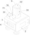
FIG. 1 is a schematic diagram of the overall structure of an embodiment of the present invention;
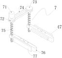
FIG. 2 is a sectional view of a dust box according to an embodiment of the present invention;
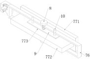
FIG. 3 is a schematic view of a cleaning assembly according to an embodiment of the present invention;
fig. 4 is a sectional view of the drive cartridge in the embodiment of the present invention.
In the figure: 1-a dust removal box; 2-sealing the door; 3-a dust collection assembly; 31-an exhaust fan; 32-a dust extraction box; 33-a dust extraction port; 4-a vent; 5-filter plate, 6-sliding rail; 7-a cleaning component; 71-cleaning the motor; 72-a first carousel; 73-a second carousel; 74-a belt; 75-reciprocating screw rod; 76-a drive cartridge; 77-a cleaning member; 771-cleaning cotton board; 772-connecting plates; 773-card slot; 8-bolt; 9-clamping plate; 10-a guide rod; 11-support seat.
Detailed Description
Example (b): please refer to fig. 1-4, a dust removing device for decoration engineering, comprising a dust removing box 1, one side of the dust removing box 1 is hinged with a sealing door 2, the top of the dust removing box 1 is provided with a dust collecting component 3 for sucking dust into the dust removing box 1, the outer walls of two sides of the dust removing box 1 are symmetrically provided with a plurality of ventilation openings 4, and the ventilation openings 4 are arranged in parallel at equal intervals, a filter plate 5 is movably arranged at the position close to the ventilation opening 4 in the dust removing box 1, and a cleaning component 7 for cleaning the filter plate 5 is arranged at the position close to the filter plate 5 in the dust removing box 1.
Design like this, when carrying out dust removal work, can be under the operation of taking out the dirt subassembly, with the outside air suction dust removal case 1 that contains the dust in, filter 5 filters the dust in the air, and the air accessible vent 4 after the filtration discharge dust removal case 1 is outside for the dust is stayed in dust removal case 1, removes dust to the realization to external environment.
The filter plates 5 are cleaned by the cleaning assembly 7 while dust is removed, and then dust attached to the filter plates 5 is removed, so that the dust is prevented from being blocked by the dust attached to the filter plates 5, and the dust removing efficiency and effect of the device are prevented from being affected.
As shown in fig. 1, the dust collection assembly 3 includes an exhaust fan 31 fixedly installed at the top of the dust collection box 1, a dust collection box 32 is installed on the dust collection box 1 at one side of the exhaust fan 31, and an input end of the exhaust fan 31 is communicated with the dust collection box 32.
A dust extraction opening 33 is formed in the outer wall of one side of the dust extraction box 32, and the bottom of the dust extraction box 32 is communicated with the dust removal box 1.
The exhaust fan 31 is started, the exhaust fan 31 extracts air in the dust box 32, so that vacuum is generated in the dust box 32, and air containing dust outside is sucked into the dust box 32 through the dust removing opening and then flows into the dust removing box 1 for dust removal.
As shown in fig. 2, sliding rails 6 are fixedly installed at positions on the inner walls of two sides of the dust removing box 1, which are close to the filter plates 5, and the two filter plates 5 are respectively connected with the corresponding sliding rails 6 in a sliding manner.
Design like this, when filter 5 damages when needing to be changed, only need open sealing door 2, later pulling filter 5, roll-off to the dust removal case 1 outside in the filter 5 follow slip track 6, just so accomplished the dismantlement of filter 5 to people dismantle the change to the filter screen board that damages, not only effectively avoid influencing the normal operating of the device, and greatly reduced staff's the work degree of difficulty and intensity, simultaneously greatly reduced cost of maintenance.
As shown in fig. 1, a support seat 11 is fixedly installed on one side of the top of the filter box.
As shown in fig. 1-3, the cleaning assembly 7 includes a cleaning motor 71 fixedly mounted on the top of the supporting seat 11, a power output end of the cleaning motor 71 penetrates through the supporting seat 11 and is fixedly connected with a first rotating disc 72, and a second rotating disc 73 is disposed on one side of the first rotating disc 72 on the top of the dust removing box 1.
A transmission belt 74 is arranged between the first rotating disc 72 and the second rotating disc 73, and the first rotating disc 72 and the second rotating disc 73 are in transmission connection through the transmission belt 74.
The bottom of the first rotating disc 72 and the bottom of the second rotating disc 73 are fixedly connected with reciprocating screw rods 75, and the bottom ends of the reciprocating screw rods 75 penetrate through the top of the dust removal box 1, extend into the dust removal box 1 and are connected with the inner wall of the bottom of the dust removal box 1 in a rotating mode.
All threaded connection has drive box 76 on the reciprocal lead screw 75, and the both sides of drive box 76 all with the inner wall sliding connection of dust removal case 1, can dismantle on the drive box 76 and be connected with cleaning member 77, cleaning member 77's clean end contacts with filter 5.
The cleaning motor 71 is started, the cleaning motor 71 rotates to drive the first rotating disc 72 to rotate, the first rotating disc 72 rotates to drive the second rotating disc 73 to synchronously rotate through the transmission belt 74, and therefore the first rotating disc 72 and the second rotating disc 73 synchronously drive the reciprocating screw rod 75 to rotate.
Because the two sides of the driving box 76 are connected with the inner wall of the dust removing box 1 in a sliding manner, the reciprocating screw rod 75 rotates to drive the driving box 76 to reciprocate up and down, the driving box 76 moves to drive the cleaning piece 77 to reciprocate up and down, and therefore the cleaning piece 77 cleans the filter plates 5 up and down in a reciprocating manner.
Design like this to effectively avoid filtering dust and block up filter 5, influence the filterable efficiency and the effect of filter 5, improved the practicality that the device used, be convenient for use widely on a large scale.
As shown in fig. 4, a bolt 8 is screwed on the top of the driving box 76, and the bottom end of the bolt 8 extends through the driving box 76 to the inside thereof and is fixedly connected with a clamping plate 9.
The cleaning member 77 comprises a brush plate in contact with the filter plate 5, and a connection plate 772 is fixedly connected to the other side of the brush plate, and the other end of the connection plate 772 penetrates the drive case 76 and extends to the outside thereof.
The connecting plate 772 is provided with a clamping groove 773 at a position corresponding to the clamping plate 9, and the clamping plate 9 is matched with the clamping groove 773.
When the bolt 8 is rotated, the bolt 8 drives the clamping plate 9 to move along the direction of the guide rod 10 under the action of the guide rod 10, and then the clamping plate 9 is inserted into the clamping groove 773 to realize the clamping connection between the clamping plate 9 and the clamping groove 773, so that the detachable connection between the driving box 76 and the cleaning piece 77 is realized.
Because the cleaning piece 77 is a worn-out article, and must be replaced after using for a period of time, the effect of cleaning the filter plate 5 can be influenced if not replaced, so that the cleaning piece 77 needs to be replaced frequently, the design is convenient for people to replace the cleaning piece 77, the influence on the normal cleaning of the filter plate 5 by the cleaning piece 77 is effectively avoided, the working difficulty and the intensity of workers are greatly reduced, and meanwhile, the maintenance cost is greatly reduced.
The sealing door 2 is provided with a transparent window, so that the working condition inside the dust removal box 1 can be observed conveniently.
A handle is fixedly mounted on one side, located on the transparent window, of the sealing door 2, and the sealing door 2 is convenient to open by an operator due to the design.
During the specific use, with the device remove to the position that needs remove dust, later open air exhauster 31, air exhauster 31 extraction dust extraction box 32 in the air for produce the vacuum in the dust extraction box 32, thereby in passing through the dust removal mouth with the outside air that contains the dust and inhaling dust extraction box 32, later flow into in the dust removal case 1 and remove dust.
After air containing dust enters the dust removal box 1, the dust in the air is filtered by the filter plates 5, and the filtered air can be discharged out of the dust removal box 1 through the ventilation openings 4, so that the dust is left in the dust removal box 1, and the dust removal of the external environment is realized.
The cleaning motor 71 is started while dust is removed, the cleaning motor 71 rotates to drive the first rotating disc 72 to rotate, the first rotating disc 72 rotates to drive the second rotating disc 73 to synchronously rotate through the transmission belt 74, and therefore the first rotating disc 72 and the second rotating disc 73 synchronously drive the reciprocating screw rod 75 to rotate.
Because the two sides of the driving box 76 are connected with the inner wall of the dust removing box 1 in a sliding manner, the reciprocating screw rod 75 rotates to drive the driving box 76 to reciprocate up and down, the driving box 76 moves to drive the cleaning piece 77 to reciprocate up and down, and therefore the cleaning piece 77 cleans the filter plate 5 up and down in a reciprocating manner, and dust is effectively prevented from blocking the filter plate 5.
After using a period, when the filter 5 damages and needs to be changed, only need open sealing door 2, later stimulate filter 5, filter 5 from the slip-out in the slip track 6 to the dust removal case 1 outside, the dismantlement of filter 5 has just so been accomplished to people dismantle the change to the filter 5 that damages, not only effectively avoid influencing the normal operating of the device, and greatly reduced staff's the work degree of difficulty and intensity, simultaneously greatly reduced cost of maintenance.
When the cleaning piece 77 needs to be replaced, the bolt 8 is rotated, the bolt 8 drives the clamping plate 9 to move out of the clamping groove 773, the clamping connection between the driving box 76 and the cleaning piece 77 is removed, then the cleaning piece 77 is moved out of the driving box 76, the cleaning piece 77 is detached, and people can detach and replace the damaged filter plate 5 conveniently, so that the cleaning effect of the cleaning piece 77 on the filter plate 5 is effectively guaranteed, the working strength and difficulty of workers are greatly reduced, and meanwhile, the maintenance cost is greatly reduced.
By adopting the technical scheme, the dust removing device is simple in structure, convenient to operate and good in dust removing effect, not only is convenient for replacing the filter plate 5, but also has the function of cleaning the filter plate 5, and can effectively prevent impurities from blocking the filter plate 5.
It will be appreciated by those skilled in the art that changes, modifications, substitutions and alterations can be made in the embodiments described above without departing from the principles and spirit of the utility model, the scope of which is defined by the appended claims.
Claims (10)
1. The utility model provides a decorate dust collector for engineering, includes dust removal case (1), its characterized in that: one side of dust removal case (1) articulates there is sealing door (2), the top of dust removal case (1) is provided with and is used for inhaling dust absorption subassembly (3) in the dust removal case (1) with the dust, a plurality of vents (4) have been seted up to the symmetry on the both sides outer wall of dust removal case (1), and a plurality of vents (4) are equidistant parallel laying, the position department activity that is close to vent (4) in dust removal case (1) is provided with filter (5), the position department that is close to filter (5) in dust removal case (1) is provided with and is used for carrying out clear clean subassembly (7) to filter (5).
2. The dust removing device for decoration engineering according to claim 1, wherein: the dust collection assembly (3) comprises an exhaust fan (31) fixedly mounted at the top of the dust collection box (1), a dust collection box (32) is arranged on one side of the dust collection box (1) located at the exhaust fan (31), and the input end of the exhaust fan (31) is communicated with the dust collection box (32).
3. The dust removing device for decoration engineering according to claim 2, wherein: a dust extraction opening (33) is arranged on the outer wall of one side of the dust extraction box (32), and the bottom of the dust extraction box (32) is communicated with the dust removal box (1).
4. The dust removing device for decoration engineering according to claim 3, wherein: the equal fixed mounting in position department of being close to filter (5) on the both sides inner wall of dust removal case (1) has slip track (6), two filters (5) respectively with corresponding slip track (6) sliding connection.
5. The dust removing device for decoration engineering of claim 4, wherein: the cleaning assembly (7) comprises a cleaning motor (71), the power output end of the cleaning motor (71) penetrates through the supporting seat (11) and is fixedly connected with a first rotating disc (72), and one side of the first rotating disc (72) is in transmission connection with a second rotating disc (73).
6. The dust removing device for decoration engineering of claim 5, wherein: the bottom of the first rotating disc (72) and the bottom of the second rotating disc (73) are fixedly connected with reciprocating screw rods (75), and the bottom ends of the reciprocating screw rods (75) penetrate through the top of the dust removal box (1), extend into the dust removal box (1), and are rotatably connected with the inner wall of the bottom of the dust removal box (1).
7. The dust removing device for decoration engineering of claim 6, wherein: all threaded connection has drive box (76) on reciprocal lead screw (75), the both sides of drive box (76) all with the inner wall sliding connection of dust removal case (1), can dismantle on drive box (76) and be connected with cleaning member (77), the clean end and the filter (5) contact of cleaning member (77).
8. The dust removing device for decoration engineering of claim 7, wherein: the top threaded connection of drive box (76) has bolt (8), and the bottom of bolt (8) runs through drive box (76) and extends to its inside and fixedly connected with cardboard (9), is close to equal fixedly connected with guide arm (10) of both sides position department on the lateral wall that cardboard (9) and bolt (8) are connected, and the other end of guide arm (10) runs through drive box (76) and extends to its outside.
9. The dust removing device for decoration engineering according to claim 8, wherein: the cleaning member (77) includes a brush plate contacting the filter plate (5), and a connection plate (772) is fixedly connected to the other side of the brush plate, and the other end of the connection plate (772) penetrates the drive case (76) and extends to the outside thereof.
10. The dust removing device for decoration engineering according to claim 9, wherein: the connecting plate (772) is provided with a clamping groove (773) at the position corresponding to the clamping plate (9), and the clamping plate (9) is matched with the clamping groove (773).
Priority Applications (1)
| Application Number | Priority Date | Filing Date | Title |
|---|---|---|---|
| CN202220236737.3U CN216755746U (en) | 2022-01-28 | 2022-01-28 | Decorate dust collector for engineering |
Applications Claiming Priority (1)
| Application Number | Priority Date | Filing Date | Title |
|---|---|---|---|
| CN202220236737.3U CN216755746U (en) | 2022-01-28 | 2022-01-28 | Decorate dust collector for engineering |
Publications (1)
| Publication Number | Publication Date |
|---|---|
| CN216755746U true CN216755746U (en) | 2022-06-17 |
Family
ID=81977970
Family Applications (1)
| Application Number | Title | Priority Date | Filing Date |
|---|---|---|---|
| CN202220236737.3U Active CN216755746U (en) | 2022-01-28 | 2022-01-28 | Decorate dust collector for engineering |
Country Status (1)
| Country | Link |
|---|---|
| CN (1) | CN216755746U (en) |
-
2022
- 2022-01-28 CN CN202220236737.3U patent/CN216755746U/en active Active
Similar Documents
| Publication | Publication Date | Title |
|---|---|---|
| CN215822594U (en) | Dust collecting equipment that modularization industrial production used | |
| CN109224646A (en) | A kind of air cleaning facility with dust-extraction unit | |
| CN216755746U (en) | Decorate dust collector for engineering | |
| CN213739831U (en) | Textile dust collecting device on cellulose fiber yarn-dyed fabric textile machine | |
| CN111203325B (en) | Electrostatic dust removal equipment | |
| CN217855104U (en) | Efficient dust removal device for workshop for stone processing | |
| CN215310918U (en) | Pulse bag type dust collector convenient to clean | |
| CN213668193U (en) | HEPA structure filter screen | |
| CN213965594U (en) | Dust collecting device for machining equipment | |
| CN210931164U (en) | Dust collecting box for dust collector | |
| CN209254325U (en) | A kind of air cleaning facility with dust-extraction unit | |
| CN220513670U (en) | Cloth bag dust remover for producing sodium tert-butoxide | |
| CN214914403U (en) | Multi-cylinder dust removal unit | |
| CN219120691U (en) | Intelligent self-cleaning fresh air machine | |
| CN216489094U (en) | Power distribution cabinet capable of removing dust inside | |
| CN220424813U (en) | Cloth bag dust removal air purifying chamber structure | |
| CN218740862U (en) | Air filter for air compressor | |
| CN219603776U (en) | Wool opening impurity removing machine | |
| CN219120693U (en) | New fan purifies | |
| CN212523426U (en) | Dust removal cooling arrangement of weaving equipment | |
| CN219682003U (en) | Treatment device for treating organic waste gas | |
| CN218955570U (en) | Environment-friendly cooling tower | |
| CN220736741U (en) | SCR flue gas denitration equipment | |
| CN218880191U (en) | Fly frame ash cleaner | |
| CN218340598U (en) | Supporting dust collector of rotor spinner |
Legal Events
| Date | Code | Title | Description |
|---|---|---|---|
| GR01 | Patent grant | ||
| GR01 | Patent grant |