CN216744017U - Guardrail lamp device with low illumination position - Google Patents

Guardrail lamp device with low illumination position Download PDF

Info

Publication number
CN216744017U
CN216744017U CN202220193931.8U CN202220193931U CN216744017U CN 216744017 U CN216744017 U CN 216744017U CN 202220193931 U CN202220193931 U CN 202220193931U CN 216744017 U CN216744017 U CN 216744017U
Authority
CN
China
Prior art keywords
plate
cover
lower cover
light source
light
Prior art date
Legal status (The legal status is an assumption and is not a legal conclusion. Google has not performed a legal analysis and makes no representation as to the accuracy of the status listed.)
Active
Application number
CN202220193931.8U
Other languages
Chinese (zh)
Inventor
翟学华
Current Assignee (The listed assignees may be inaccurate. Google has not performed a legal analysis and makes no representation or warranty as to the accuracy of the list.)
Jiangyin Yichuan Electrical Equipment Co ltd
Original Assignee
Jiangyin Yichuan Electrical Equipment Co ltd
Priority date (The priority date is an assumption and is not a legal conclusion. Google has not performed a legal analysis and makes no representation as to the accuracy of the date listed.)
Filing date
Publication date
Application filed by Jiangyin Yichuan Electrical Equipment Co ltd filed Critical Jiangyin Yichuan Electrical Equipment Co ltd
Priority to CN202220193931.8U priority Critical patent/CN216744017U/en
Application granted granted Critical
Publication of CN216744017U publication Critical patent/CN216744017U/en
Active legal-status Critical Current
Anticipated expiration legal-status Critical

Links

Images

Landscapes

  • Securing Globes, Refractors, Reflectors Or The Like (AREA)

Abstract

本实用新型涉及的一种低照位护栏灯装置,它包括上盖、下盖、光源板、透镜、盖板、玻璃板和底座;所述上盖设置在下盖上方并与下盖匹配卡合,所述下盖为顶面开口的盒体,所述下盖包括外壳和内壳,所述外壳的一个侧面上设有一个长方形的槽口,该槽口与所述内壳之间设有一个灯体室,所述灯体室内设有一块尺寸匹配的光源板,所述光源板上设有多个等距分布的光源,所述光源上罩设有透镜,所述光源板上设有盖板,所述盖板上设有多个与透镜匹配的透镜孔;所述外壳的槽口上设置一块玻璃板,将灯体室密封;所述下盖通过连接支架与底座铰接。本实用新型结构简单紧凑,灯体连接牢固,并且检修时仅需拆卸卡接的上盖,因此安装检修维护方便,省时省力。

Figure 202220193931

The utility model relates to a low illumination position guardrail lamp device, which comprises an upper cover, a lower cover, a light source plate, a lens, a cover plate, a glass plate and a base; the upper cover is arranged above the lower cover and is matched and engaged with the lower cover , the lower cover is a box body with an open top surface, the lower cover includes an outer shell and an inner shell, one side of the outer shell is provided with a rectangular slot, and a slot is provided between the slot and the inner shell A lamp body room, a light source board of matching size is arranged in the lamp body room, a plurality of light sources distributed at equal distances are arranged on the light source plate, a lens is arranged on the cover of the light source, and a light source plate is arranged on the light source plate The cover plate is provided with a plurality of lens holes matching the lenses; a glass plate is arranged on the notch of the casing to seal the lamp body chamber; the lower cover is hinged with the base through the connecting bracket. The utility model has the advantages of simple and compact structure, firm connection of the lamp body, and only needs to disassemble the clamped upper cover during maintenance, so the installation, maintenance, and maintenance are convenient and time-saving and labor-saving.

Figure 202220193931

Description

Guardrail lamp device with low illumination position
Technical Field
The utility model relates to the technical field of guardrail lamps, in particular to a guardrail lamp device with a low illumination position.
Background
In urban road lighting, a traditional solution is to use a high-pole street lamp as a lighting appliance, and the biggest disadvantage of the solution is to bring light pollution to surrounding residences at night and consume a large amount of electric energy. The LED guardrail lamp has good lighting effect, uniform road lighting, less glare, no light pollution, reduced overall energy consumption and energy conservation, and the single product has the functions of road lighting, landscape lighting and road collision avoidance, so the LED guardrail lamp is widely applied to the lighting engineering of roads, bridges, viaducts, overpasses, riverways and the like.
The guardrail lamp is a road lamp arranged on a road guardrail, can play roles in beautifying cities, illuminating roads and bridges, dredging safety and the like, and generally takes a fluorescent tube or a light-emitting diode as a light source and takes a continuous guardrail as a carrier to form a linear or approximately linear guardrail lamp strip.
The existing guardrail lamp is generally formed by arranging light sources such as a fluorescent lamp tube or a light-emitting diode in a plastic pipe, light emitted by the light sources in the guardrail lamp can be directly emitted out through the plastic pipe, the light-emitting angle of the guardrail lamp is basically not controlled, a large amount of light is emitted to the sky and the like, and therefore the light emitted by the light sources cannot be effectively utilized and energy waste is caused.
SUMMERY OF THE UTILITY MODEL
The utility model aims to overcome the defects and provide the low-illumination guardrail lamp device which is anti-fog and anti-glare and effectively utilizes light rays emitted by the light source of the guardrail lamp.
The purpose of the utility model is realized as follows:
a guardrail lamp device at a low illumination position comprises an upper cover, a lower cover, a light source plate, a lens, a cover plate, a glass plate and a base; the upper cover is arranged above the lower cover and is matched and clamped with the lower cover, the lower cover is a box body with an opening in the top surface, the lower cover comprises an outer shell and an inner shell, a rectangular notch is formed in one side surface of the outer shell, a lamp body chamber is arranged between the notch and the inner shell, a light source plate with matched size is arranged in the lamp body chamber, a plurality of light sources distributed at equal intervals are arranged on the light source plate, lenses are covered on the light sources, a cover plate is arranged on the light source plate, and a plurality of lens holes matched with the lenses are formed in the cover plate; a glass plate is arranged on the notch of the shell and clamped with the notch to seal the lamp body chamber; the lower cover is hinged with the base through a connecting support.
Further, a waterproof ring is arranged between the upper cover and the lower cover for connection and sealing.
Further, the light source board and the cover board are both disposed obliquely forward.
Furthermore, a circuit board box is arranged on the bottom surface of the inner shell and used for placing a circuit board.
Furthermore, the center of the bottom surface of the inner shell is provided with a connecting hole, and the connecting hole penetrates through the outer shell and is used for connecting the base.
Further, the base comprises a base body and a hinge pin shaft, a shaft support is arranged on the base body, and the hinge pin shaft is arranged on the shaft support.
Further, the connecting support comprises a horizontal flat plate and two side plates which are in an inverted U shape, and the two side plates are respectively connected with the hinge pin shafts in a matched mode.
Furthermore, a circle of angle scales are arranged on the side plate and distributed around the circumference of the screw hole on the side plate.
Furthermore, a power interface is arranged on the lower cover and penetrates through the outer shell and the inner shell.
Furthermore, a breather valve hole is formed in the lower cover and used for assembling the breather valve.
Compared with the prior art, the utility model has the beneficial effects that:
the utility model has simple and compact structure, firm connection of the lamp body, and convenient installation, maintenance and repair as long as the clamped upper cover is detached during maintenance, thereby saving time and labor. The utility model has the advantages of convenient assembly, good sealing performance, water resistance, fog resistance, lower manufacturing cost and wide applicability; the angle of the lamp body is adjustable, the base is arranged on the guardrail wall and is hinged with the shell for placing the lamp body through the bracket, so that the angle of the lamp body is adjusted to be optimal, and light rays emitted by a light source of the guardrail lamp are effectively utilized; the light source plate is obliquely arranged, the lens is used for refracting the light source, the special street lamp is used for light distribution, the light source plate is suitable for human eyes, and smooth surface glass sealing is adopted, so that dazzling of the light source is reduced, dizzy prevention is realized, and hidden dangers of traffic accidents are reduced.
Drawings
FIG. 1 is a schematic view of the present invention.
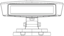
Fig. 2 is a front view of the present invention.
Fig. 3 is an exploded view of the present invention.
Fig. 4 is a schematic structural view of the lower cover of the present invention.
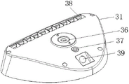
Fig. 5 is a schematic view of another angle structure of the lower cover of the present invention.
Fig. 6 is a schematic cross-sectional view of the lower cap of the present invention.
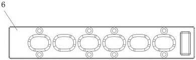
Fig. 7 is a front view of the cover plate of the present invention.
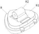
Fig. 8 is a schematic structural diagram of the base of the present invention.
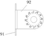
Fig. 9 is a side view of the attachment bracket of the present invention.
Fig. 10 is a top view of the connecting bracket of the present invention.
Wherein:
the LED lamp comprises an upper cover 1, a waterproof ring 2, a lower cover 3, an outer shell 31, an inner shell 32, a reinforcing plate 33, a lamp body chamber 34, a circuit board box 35, a connecting hole 36, a breathing valve hole 37, a heat dissipation hole 38, a power supply interface 39, a light source plate 4, a lens 5, a cover plate 6, a glass plate 7, a base 8, a supporting platform 81, a hinge pin shaft 82, a connecting support 9, a flat plate 91, a side plate 92, a screw hole 93 and a limiting hole 94.
Detailed Description
For a better understanding of the technical aspects of the present invention, reference will now be made in detail to the accompanying drawings. It should be understood that the following specific examples are not intended to limit the embodiments of the present invention, but are merely exemplary embodiments of the present invention. It should be noted that the description of the positional relationship of the components, such as the component a is located above the component B, is based on the description of the relative positions of the components in the drawings, and is not intended to limit the actual positional relationship of the components.
Example 1:
referring to fig. 1-10, fig. 1 depicts a schematic view of a low level guardrail light assembly. As shown in the figure, the guardrail lamp device at the low illumination position comprises an upper cover 1, a lower cover 3, a light source plate 4, a lens 5, a cover plate 6, a glass plate 7 and a base 8.
The upper cover 1 is arranged above the lower cover 3 and is matched and clamped with the lower cover 3, and the waterproof ring 2 is arranged between the upper cover 1 and the lower cover 3 for connection and sealing.
The lower cover 3 is a box body with an opening on the top surface, the lower cover 3 comprises an outer shell 31 and an inner shell 32, a rectangular notch is formed in one side surface of the outer shell 31, a lamp body chamber 34 is arranged between the notch and the inner shell 32, a reinforcing plate 33 is arranged on one side, close to the inner shell 32, of the lamp body chamber 34 for reinforcement, and a plurality of reinforcing ribs are arranged on the reinforcing plate 33; the lamp body chamber 34 is internally provided with a light source plate 4 with matched size, the light source plate 4 is provided with a plurality of light sources distributed at equal intervals, the light source upper cover is provided with a lens 5, the light source plate 4 is provided with a cover plate 6, the cover plate 6 is provided with a plurality of lens holes matched with the lens 5, the edge of the cover plate 6 is provided with a plurality of screw holes for inserting cross-recessed countersunk head screws to fix the cover plate 6 on the light source plate 4, the light source plate 4 and the cover plate 6 are both obliquely and forwardly arranged, and the inclination angle between the light source plate 4 and a radial line is 10-60 degrees.
A glass plate 7 is provided on the notch of the housing 31, and the glass plate 7 is engaged with the notch to seal the lamp body chamber 34.
A circuit board box 35 is arranged on the bottom surface of the inner shell 32 and used for placing a circuit board.
The center of the bottom surface of the inner shell 32 is provided with a connecting hole 36, and the connecting hole 36 penetrates through the outer shell 31 and is used for connecting the base 8; one side of the connecting hole 36 is provided with a breathing valve hole 37 for assembling the breathing valve; one side of the breathing valve hole 37 is provided with a power interface 39, and the power interface 39 penetrates through the shell 31 and is used for connecting a power supply.
The bottom edge of the housing 31 is provided with a row of heat dissipation holes 38 for dissipating heat.
The base 8 comprises a base body, a supporting platform 81 and a hinge pin shaft 82, wherein the supporting platform 81 is arranged on the base body, a shaft support is arranged on the supporting platform 81, the hinge pin shaft 82 is arranged on the shaft support, arc-shaped sliding grooves are respectively formed in two ends of the shaft support and are respectively arranged on two sides of the hinge pin shaft 82.
Be connected through linking bridge 9 between lower cover 3 and the base 8, linking bridge 9 is the U type of invering including horizontal dull and stereotyped 91 and two curb plates 92, and two curb plates 92 set up respectively in the both sides of articulated round pin axle 82, all be equipped with screw hole 93 on dull and stereotyped 91 and the curb plate 92, screw hole 93 on the dull and stereotyped 91 inserts outer hexagonal screw and is connected with the connecting hole 36 of lower cover 3, and is fixed through outer hexagonal nut, spring washer and flat pad.
The screw hole 93 on the side plate 92 is matched with the hinge pin shaft 82, and is hinged by inserting an outer hexagonal screw, a spring washer and a flat gasket and fixed by an outer hexagonal nut; when the angle of the connecting bracket 9 is adjusted, the bottom edge of the side plate 92 slides in the arc-shaped sliding groove of the shaft support, so that the hinging is realized.
The screw hole 93 on the flat plate 91 is arranged at the center of the flat plate 91, and two sides of the screw hole 93 on the flat plate 91 are respectively provided with a limit hole 94 for limiting the angle adjusted by the connecting bracket 9.
The side plate 92 is provided with a circle of angle scales which are circumferentially distributed around the screw hole 93 of the side plate 92 and used for marking the angle adjusted by the connecting bracket 9.
The waterproof ring 2 is a waterproof silica gel ring.
The cover plate 6 is a low-altitude guardrail lamp PC cover plate.
The glass plate 7 is low-altitude projection lamp super-white smooth glass, and a circle of the edge is provided with a black printing edge.
The above is only a specific application example of the present invention, and the protection scope of the present invention is not limited in any way. All the technical solutions formed by equivalent transformation or equivalent replacement fall within the protection scope of the present invention.

Claims (10)

1.一种低照位护栏灯装置,其特征在于:它包括上盖(1)、下盖(3)、光源板(4)、透镜(5)、盖板(6)、玻璃板(7)和底座(8);所述上盖(1)设置在下盖(3)上方并与下盖(3)匹配卡合, 所述下盖(3)为顶面开口的盒体,所述下盖(3)包括外壳(31)和内壳(32),所述外壳(31)的一个侧面上设有一个长方形的槽口,该槽口与所述内壳(32)之间设有一个灯体室(34),所述灯体室(34)内设有一块尺寸匹配的光源板(4),所述光源板(4)上设有多个等距分布的光源,所述光源上罩设有透镜(5),所述光源板(4)上设有盖板(6),所述盖板(6)上设有多个与透镜(5)匹配的透镜孔;所述外壳(31)的槽口上设置一块玻璃板(7),玻璃板(7)与槽口卡合,将灯体室(34)密封;所述下盖(3)通过连接支架(9)与底座(8)铰接。1. A low-lighting position guardrail lamp device, characterized in that: it comprises an upper cover (1), a lower cover (3), a light source plate (4), a lens (5), a cover plate (6), a glass plate (7) ) and the base (8); the upper cover (1) is arranged above the lower cover (3) and is matched and engaged with the lower cover (3), the lower cover (3) is a box body with an open top surface, and the lower cover (3) is a box body with an open top surface. The cover (3) includes an outer shell (31) and an inner shell (32), one side surface of the outer shell (31) is provided with a rectangular slot, and a slot is provided between the slot and the inner shell (32). A lamp body chamber (34), a light source board (4) of matching size is arranged in the lamp body chamber (34), a plurality of light sources distributed at equal distances are arranged on the light source board (4), and the light source The cover is provided with a lens (5), the light source plate (4) is provided with a cover plate (6), and the cover plate (6) is provided with a plurality of lens holes matched with the lens (5); the housing ( A glass plate (7) is arranged on the notch of 31), and the glass plate (7) is engaged with the notch to seal the lamp body chamber (34); the lower cover (3) is connected to the base (8) by connecting the bracket (9) ) hinged. 2.根据权利要求1所述的一种低照位护栏灯装置,其特征在于:所述上盖(1)和下盖(3)之间设置防水圈(2)连接密封。2 . The low-light-level guardrail light device according to claim 1 , wherein a waterproof ring ( 2 ) is provided between the upper cover ( 1 ) and the lower cover ( 3 ) to connect and seal. 3 . 3.根据权利要求1所述的一种低照位护栏灯装置,其特征在于:所述光源板(4)和盖板(6)均倾斜向前布置。3 . The low-light-level guardrail light device according to claim 1 , wherein the light source plate ( 4 ) and the cover plate ( 6 ) are both inclined and arranged forward. 4 . 4.根据权利要求1所述的一种低照位护栏灯装置,其特征在于:所述内壳(32)的底面上设有一个线路板盒(35),用于放置线路板。4 . The low-light level guardrail light device according to claim 1 , wherein a circuit board box ( 35 ) is provided on the bottom surface of the inner shell ( 32 ) for placing circuit boards. 5 . 5.根据权利要求1所述的一种低照位护栏灯装置,其特征在于:所述内壳(32)的底面中心设有一个连接孔(36),连接孔(36)贯穿外壳(31),用于连接底座(8)。5 . The low-light level guardrail light device according to claim 1 , wherein a connecting hole ( 36 ) is provided in the center of the bottom surface of the inner shell ( 32 ), and the connecting hole ( 36 ) penetrates the outer shell ( 31 ). 6 . ) for connecting the base (8). 6.根据权利要求1所述的一种低照位护栏灯装置,其特征在于:所述底座(8)包括底座本体和铰接销轴(82),所述底座本体上设有一个轴托,轴托上设置铰接销轴(82)。6. A low-lighting position guardrail lamp device according to claim 1, characterized in that: the base (8) comprises a base body and a hinge pin (82), and the base body is provided with a shaft support, A hinge pin (82) is arranged on the shaft support. 7.根据权利要求6所述的一种低照位护栏灯装置,其特征在于:所述连接支架(9)包括横置的平板(91)和两个侧板(92),呈倒置的U型,两个侧板(92)分别与铰接销轴(82)匹配连接。7. A low-lighting position guardrail light device according to claim 6, characterized in that: the connecting bracket (9) comprises a horizontal flat plate (91) and two side plates (92), which are inverted U type, the two side plates (92) are respectively matched and connected with the hinge pins (82). 8.根据权利要求7所述的一种低照位护栏灯装置,其特征在于:所述侧板(92)上设有一圈角度刻度,围绕侧板(92)上的螺丝孔(93)圆周分布。8. A low-lighting position guardrail light device according to claim 7, characterized in that: the side plate (92) is provided with a circle of angle scales surrounding the circumference of the screw hole (93) on the side plate (92). distributed. 9.根据权利要求1所述的一种低照位护栏灯装置,其特征在于:所述下盖(3)上设有一个电源接口(39),电源接口(39)贯穿外壳(31)和内壳(32)。9 . The low-light level guardrail light device according to claim 1 , characterized in that: the lower cover ( 3 ) is provided with a power interface ( 39 ), and the power interface ( 39 ) penetrates through the casing ( 31 ) and inner shell (32). 10.根据权利要求1所述的一种低照位护栏灯装置,其特征在于:所述下盖(3)上设有一个呼吸阀孔(37),用于装配呼吸阀。10 . The low-light level guardrail light device according to claim 1 , wherein the lower cover ( 3 ) is provided with a breathing valve hole ( 37 ) for assembling the breathing valve. 11 .
CN202220193931.8U 2022-01-25 2022-01-25 Guardrail lamp device with low illumination position Active CN216744017U (en)

Priority Applications (1)

Application Number Priority Date Filing Date Title
CN202220193931.8U CN216744017U (en) 2022-01-25 2022-01-25 Guardrail lamp device with low illumination position

Applications Claiming Priority (1)

Application Number Priority Date Filing Date Title
CN202220193931.8U CN216744017U (en) 2022-01-25 2022-01-25 Guardrail lamp device with low illumination position

Publications (1)

Publication Number Publication Date
CN216744017U true CN216744017U (en) 2022-06-14

Family

ID=81915820

Family Applications (1)

Application Number Title Priority Date Filing Date
CN202220193931.8U Active CN216744017U (en) 2022-01-25 2022-01-25 Guardrail lamp device with low illumination position

Country Status (1)

Country Link
CN (1) CN216744017U (en)

Similar Documents

Publication Publication Date Title
CN201636626U (en) Round LED flood light
CN206647911U (en) A kind of reflective LED road lamp
CN204806077U (en) High -power LED projecting lamp
CN216644003U (en) Waterproof LED street lamp with power cavity
CN212204141U (en) A multifunctional moon lamp
CN201753874U (en) An asymmetric lens type LED street lamp
CN210511220U (en) Guardrail lighting lamp holder
CN201772353U (en) An LED street lamp with integral interface
CN207815097U (en) A kind of LED bay light of adjustable light-emitting angle
CN205331988U (en) Outdoor LED projecting lamp
CN216480679U (en) Multi-functional projecting lamp that waterproof gas permeability is good
CN220828834U (en) LED linear underground lamp
CN218936280U (en) Waterproof focusing ground lamp of structure
CN220489108U (en) A spherical street light with good heat dissipation effect and waterproof
CN223512038U (en) High-performance underwater projection lamp
CN222142987U (en) Photoelectric split type die-casting annular UFO industrial and mining lamp
CN208365327U (en) A kind of LED street lamp of comprehensive heat dissipation extra-high photo effect
CN205383507U (en) Convenient assembling and good heat dissipation's projecting lamp
CN214948431U (en) Wall lamp is drawn to quicksand
CN216383820U (en) An LED buried floodlight with adjustable illumination angle
CN221444098U (en) Tool-free light distribution type lamp
CN211450542U (en) LED projection lamp
CN221991722U (en) Linear lamps and lanterns that anti-dazzle is splendid
CN208365285U (en) Garden lamp LED garden lamp light source on a kind of column
CN203963605U (en) LED light fixture

Legal Events

Date Code Title Description
GR01 Patent grant
GR01 Patent grant
PE01 Entry into force of the registration of the contract for pledge of patent right

Denomination of utility model: A low light level guardrail light device

Effective date of registration: 20221021

Granted publication date: 20220614

Pledgee: Jiangyin Xinlian Financing Guarantee Co.,Ltd.

Pledgor: Jiangyin Yichuan Electrical Equipment Co.,Ltd.

Registration number: Y2022980019176

PC01 Cancellation of the registration of the contract for pledge of patent right

Date of cancellation: 20231008

Granted publication date: 20220614

Pledgee: Jiangyin Xinlian Financing Guarantee Co.,Ltd.

Pledgor: Jiangyin Yichuan Electrical Equipment Co.,Ltd.

Registration number: Y2022980019176

PC01 Cancellation of the registration of the contract for pledge of patent right
PE01 Entry into force of the registration of the contract for pledge of patent right

Denomination of utility model: A low light level guardrail light device

Effective date of registration: 20231031

Granted publication date: 20220614

Pledgee: Jiangyin Xinlian Financing Guarantee Co.,Ltd.

Pledgor: Jiangyin Yichuan Electrical Equipment Co.,Ltd.

Registration number: Y2023980063267

PE01 Entry into force of the registration of the contract for pledge of patent right
PC01 Cancellation of the registration of the contract for pledge of patent right

Granted publication date: 20220614

Pledgee: Jiangyin Xinlian Financing Guarantee Co.,Ltd.

Pledgor: Jiangyin Yichuan Electrical Equipment Co.,Ltd.

Registration number: Y2023980063267

PC01 Cancellation of the registration of the contract for pledge of patent right
PE01 Entry into force of the registration of the contract for pledge of patent right

Denomination of utility model: A low illumination guardrail light device

Granted publication date: 20220614

Pledgee: Jiangyin Xinlian Financing Guarantee Co.,Ltd.

Pledgor: Jiangyin Yichuan Electrical Equipment Co.,Ltd.

Registration number: Y2024980046020

PE01 Entry into force of the registration of the contract for pledge of patent right
PC01 Cancellation of the registration of the contract for pledge of patent right

Granted publication date: 20220614

Pledgee: Jiangyin Xinlian Financing Guarantee Co.,Ltd.

Pledgor: Jiangyin Yichuan Electrical Equipment Co.,Ltd.

Registration number: Y2024980046020

PC01 Cancellation of the registration of the contract for pledge of patent right
PE01 Entry into force of the registration of the contract for pledge of patent right

Denomination of utility model: A low light level guardrail light device

Granted publication date: 20220614

Pledgee: Jiangyin Xinlian Financing Guarantee Co.,Ltd.

Pledgor: Jiangyin Yichuan Electrical Equipment Co.,Ltd.

Registration number: Y2025980043974

PE01 Entry into force of the registration of the contract for pledge of patent right