Support revolving stage convenient to dismantle and overhaul
Technical Field
The utility model relates to a support revolving stage technical field specifically is a support revolving stage convenient to dismantle and overhaul.
Background
The support rotary table is a rotary table monitoring camera with a mounting support, the support rotary table can rotate the azimuth, the focal length of a lens and the focusing position of the lens in real time during monitoring, and the zooming and focusing control speed is continuously adjustable, so that the support rotary table is commonly used in the field of frontier defense, sea defense or civil defense with a large monitoring range.
And because the external environment in frontier defense, sea defense or civil air defense is comparatively abominable, and conventional support revolving stage adopts the bolt to install it fixedly mostly, and the operation is comparatively loaded down with trivial details, consequently can not carry out convenient stable dismantlement when the support revolving stage takes place to damage and overhauls and subsequent installation fixed work, and the practicality is relatively poor.
We have therefore proposed a support turret that is easy to disassemble and repair in order to solve the problems set out above.
SUMMERY OF THE UTILITY MODEL
An object of the utility model is to provide a support revolving stage convenient to dismantle and overhaul to solve the problem that convenient stable dismantlement was overhauld and subsequent installation fixed work can not be carried out to the support revolving stage on the existing market that above-mentioned background art provided.
In order to achieve the above object, the utility model provides a following technical scheme: the utility model provides a support revolving stage convenient to dismantle and overhaul, includes the mounting panel, welded fastening has spacing frame on the mounting panel, spacing sliding connection has the fixed plate in the spacing frame, the top welded fastening of fixed plate has support revolving stage body, the draw-in groove has been seted up on the fixed plate, the mounting panel internal rotation is connected with worm and fixed axle, the meshing is connected with the worm wheel on the worm, equal welded fastening of worm wheel and rotor plate is on the fixed axle, run through on the rotor plate and seted up the guide way, spacing sliding connection has the guide bar in the guide way, guide bar welded fastening is on linking the pole.
Preferably, the diameter of the inner space of the limiting frame is equal to that of the fixing plate, the diameter of the fixing plate is larger than that of the support turntable body, and the central axis of the worm wheel and the central axis of the mounting plate are located on the same vertical central line.
Preferably, the guide grooves are distributed on the rotating plate at equal angles, the guide grooves correspond to the guide rods one by one, and the rotating plate and the guide rods are symmetrically distributed on the upper side and the lower side of the connecting rod.
Preferably, the other end welded fastening of joint pole has the grip block, the screw connection has kelly and rubber slab on the grip block, the kelly block is connected in the draw-in groove, the spacing groove has been seted up in the mounting panel, the equal spacing sliding connection of joint pole and grip block is at the spacing inslot.
Preferably, the connecting rod is fixed at the middle part of the bottom of the clamping plate, the clamping plate is arc-shaped, and the width of the clamping plate is larger than the thickness of the fixing plate.
Preferably, the clamping rod is fixed in the middle of the clamping plate, the length of the clamping rod is smaller than that of the clamping groove, and the clamping plate is connected in the limiting frame in a limiting sliding mode.
Compared with the prior art, the beneficial effects of the utility model are that: the support turntable is convenient to disassemble and overhaul;
1. the support turntable is provided with the limiting frames and the clamping rods, the support turntable body can be conveniently and stably positioned by utilizing the limiting between the limiting frames and the fixing plate, then each clamping rod can be driven to be inserted into the clamping groove by combining the motion of each clamping plate, and then the clamping and mounting work of the support turntable body can be conveniently and stably completed;
2. this support revolving stage is provided with grip block and rubber slab, utilizes the rotation of worm and worm wheel, combines the guide way on the rotor plate to drive the grip block on each links up the pole simultaneously to the intermediate motion, and then can carry out convenient efficient centre gripping fixed work to support revolving stage body, meanwhile, combines the rubber slab can further improve the centre gripping stability, can carry out stable buffering protection work to support revolving stage body simultaneously, has increased the safety in utilization and the stability of support revolving stage.
Drawings
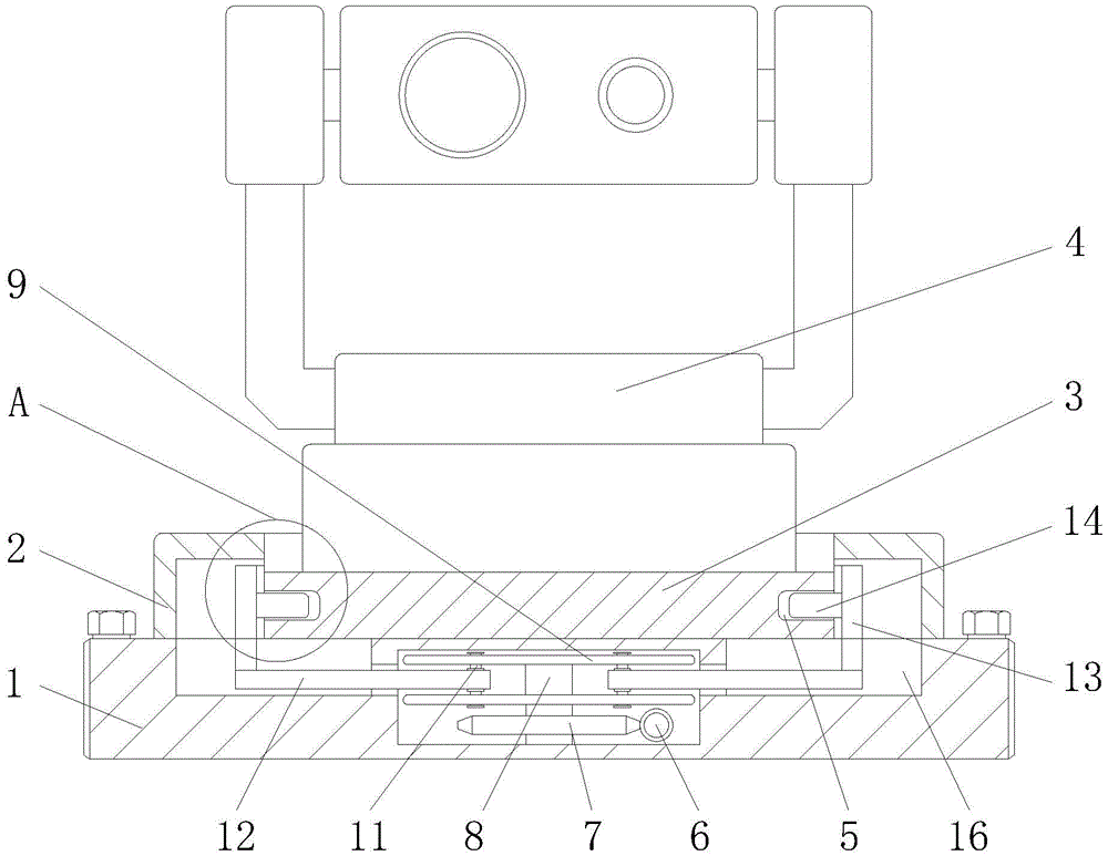
FIG. 1 is a schematic view of the overall structure of the present invention;
FIG. 2 is a schematic view of the structure at A in FIG. 1 according to the present invention;
fig. 3 is a schematic top view of the worm wheel according to the present invention;
fig. 4 is a schematic top view of the guide groove of the present invention;
fig. 5 is a schematic view of the top view structure of the clamping plate of the present invention.
In the figure: 1. mounting a plate; 2. a limiting frame; 3. a fixing plate; 4. a support turntable body; 5. a card slot; 6. a worm; 7. a worm gear; 8. a fixed shaft; 9. a rotating plate; 10. a guide groove; 11. a guide bar; 12. a connecting rod; 13. a clamping plate; 14. a clamping rod; 15. a rubber plate; 16. a limiting groove.
Detailed Description
The technical solutions in the embodiments of the present invention will be described clearly and completely with reference to the accompanying drawings in the embodiments of the present invention, and it is obvious that the described embodiments are only some embodiments of the present invention, not all embodiments. Based on the embodiments in the present invention, all other embodiments obtained by a person skilled in the art without creative work belong to the protection scope of the present invention.
Referring to fig. 1-5, the present invention provides a technical solution: the utility model provides a support revolving stage convenient to dismantle and overhaul, including mounting panel 1, welded fastening has spacing frame 2 on the mounting panel 1, spacing sliding connection has fixed plate 3 in the spacing frame 2, the top welded fastening of fixed plate 3 has support revolving stage body 4, draw-in groove 5 has been seted up on the fixed plate 3, 1 internal rotation of mounting panel is connected with worm 6 and fixed axle 8, the meshing is connected with worm wheel 7 on the worm 6, worm wheel 7 and the equal welded fastening of rotor plate 9 are on fixed axle 8, the leading way 10 has been seted up in running through on the rotor plate 9, spacing sliding connection has guide bar 11 in the guide way 10, guide bar 11 welded fastening is on linking pole 12.
The inside space diameter of spacing frame 2 equals with the diameter of fixed plate 3, and the diameter of fixed plate 3 is greater than the diameter of support revolving stage body 4, and the central axis of worm wheel 7 and the central axis of mounting panel 1 are located same vertical central line, can guarantee the stability of worm wheel 7 rotation work in mounting panel 1, and then can guarantee that follow-up installation dismantles the convenience of work.
The guide grooves 10 are distributed on the rotating plate 9 at equal angles, the guide grooves 10 correspond to the guide rods 11 one by one, and the rotating plate 9 and the guide rods 11 are symmetrically distributed on the upper side and the lower side of the connecting rod 12, so that the stability of the connection state between the rotating plate 9 and the connecting rod 12 and between the guide rods 11 and the connecting rod 12 can be ensured, and the stability and convenience of subsequent driving work can be further ensured.
The other end of the linking rod 12 is fixedly welded with a clamping plate 13, a clamping rod 14 and a rubber plate 15 are connected to the clamping plate 13 through screws, the clamping rod 14 is clamped and connected in the clamping groove 5, a limiting groove 16 is formed in the mounting plate 1, the linking rod 12 and the clamping plate 13 are connected in the limiting groove 16 in a limiting sliding mode, the stability of the working state of the clamping plate 13 on the linking rod 12 can be guaranteed, and the use safety of the support rotary table is improved.
The connecting rod 12 is fixed at the middle part of the bottom of the clamping plate 13, the clamping plate 13 is arc-shaped, the width of the clamping plate 13 is larger than the thickness of the fixing plate 3, and the adverse effect of the fixing plate 3 on the clamping plate 13 can be effectively avoided.
The clamping rod 14 is fixed in the middle of the clamping plate 13, the length of the clamping rod 14 is smaller than that of the clamping groove 5, the clamping plate 13 is connected in the limiting frame 2 in a limiting mode in a sliding mode, stability of sliding operation of the clamping plate 13 in the limiting frame 2 can be guaranteed, and convenience of follow-up clamping operation can be guaranteed.
The working principle is as follows: before the support turntable convenient to disassemble and maintain is used, the overall condition of the support turntable needs to be checked firstly to determine that the support turntable can work normally; firstly, with reference to fig. 1-5, a worker can place a fixing plate 3 at the bottom of a support turntable body 4 to be installed and fixed in a limiting frame 2, and at this time, the support turntable body 4 can be stably positioned under the limiting action between the limiting frame 2 and the fixing plate 3, and then the worker can rotate a worm 6 on the mounting plate 1, and at this time, the worm 6 can drive a worm wheel 7 to stably rotate, and in the rotating process of the worm wheel 7, the rotating plate 9 can be driven to stably rotate by a fixing shaft 8, and at this time, under the continuous rotating action of the rotating plate 9, an engaging rod 12 on each guide rod 11 can be driven to simultaneously move towards the middle in a corresponding limiting groove 16 by the rotation of each guide groove 10, and further each clamping plate 13 can be driven to simultaneously move towards the middle, and at this time, each clamping rod 14 can be driven to stably insert into a corresponding clamping groove 5 on the fixing plate 3 under the action of the movement of the clamping plate 13, the clamping and mounting work of the support rotary table body 4 can be conveniently and stably completed, and similarly, when the support rotary table body 4 needs to be disassembled, a worker can drive the clamping rods 14 on the clamping plates 13 to simultaneously move outwards and separate from the clamping grooves 5 only by reversely rotating the worm 6, so that the disassembling work of the support rotary table body 4 can be conveniently and efficiently completed, and the convenience and the high efficiency of the subsequent overhauling and maintaining work of the support rotary table body 4 can be ensured;
under the action of the movement of each clamping plate 13, with reference to fig. 1, 2 and 5, the fixed plate 3 at the bottom of the support turntable body 4 can be clamped and fixed conveniently and stably, and at the same time, the rubber plate 15 on the clamping plate 13 can further improve the clamping stability, and at the same time, the support turntable body 4 on the fixed plate 3 can be buffered and protected stably, which is the working process of the whole support turntable, and the content not described in detail in this specification belongs to the prior art known by those skilled in the art.
Although the present invention has been described in detail with reference to the foregoing embodiments, it will be apparent to those skilled in the art that modifications may be made to the embodiments or portions thereof without departing from the spirit and scope of the invention.