CN216731722U - Convenient-to-move working platform for electromechanical maintenance - Google Patents
Convenient-to-move working platform for electromechanical maintenance Download PDFInfo
- Publication number
- CN216731722U CN216731722U CN202220460042.3U CN202220460042U CN216731722U CN 216731722 U CN216731722 U CN 216731722U CN 202220460042 U CN202220460042 U CN 202220460042U CN 216731722 U CN216731722 U CN 216731722U
- Authority
- CN
- China
- Prior art keywords
- plates
- base frame
- grooves
- workbench
- clamping
- Prior art date
- Legal status (The legal status is an assumption and is not a legal conclusion. Google has not performed a legal analysis and makes no representation as to the accuracy of the status listed.)
- Expired - Fee Related
Links
- 238000012423 maintenance Methods 0.000 title claims abstract description 23
- 238000005096 rolling process Methods 0.000 claims description 5
- 238000009434 installation Methods 0.000 description 3
- 230000009286 beneficial effect Effects 0.000 description 2
- 238000000034 method Methods 0.000 description 2
- 229910001294 Reinforcing steel Inorganic materials 0.000 description 1
- 230000000694 effects Effects 0.000 description 1
- 238000012986 modification Methods 0.000 description 1
- 230000004048 modification Effects 0.000 description 1
- XLYOFNOQVPJJNP-UHFFFAOYSA-N water Substances O XLYOFNOQVPJJNP-UHFFFAOYSA-N 0.000 description 1
Images


Landscapes
- Forklifts And Lifting Vehicles (AREA)
Abstract
The utility model provides a working platform convenient to move for electromechanical maintenance. The convenient-to-move working platform for electromechanical maintenance comprises a base frame; the two supporting plates are fixedly arranged at the top of the base frame; the workbench is fixedly arranged on the tops of the two supporting plates; the mounting through groove is formed in the top of the workbench; the two lifting screws are rotatably mounted at the bottom of the workbench, and the bottom ends of the two lifting screws extend into the base frame; the double-shaft motor is fixedly installed on the inner walls of the two sides of the base frame. The conveniently-moved working platform for electromechanical maintenance provided by the utility model has the advantages of simplicity in operation, high safety and convenience in carrying.
Description
Technical Field
The utility model relates to the technical field of electromechanical maintenance, in particular to a movable working platform for electromechanical maintenance.
Background
The electromechanical equipment generally refers to machinery, electrical equipment and electrical automation equipment, and in a building, the electromechanical equipment is a general name of machinery and pipeline equipment except for earthwork, carpentry, reinforcing steel bars and muddy water, which is different from hardware and can be a finished product with certain functions.
In the use of electromechanical equipment, it is easy to be bad, so that the electromechanical equipment needs to be maintained, and nowadays, because the electromechanical equipment is generally heavy, when the electromechanical equipment is maintained, the electromechanical equipment needs to be carried to a working platform manually, physical strength of workers is consumed, and in the carrying process, the electromechanical equipment may fall off, so that the electromechanical equipment is damaged more seriously.
Therefore, there is a need to provide a new and convenient movable working platform for electromechanical maintenance to solve the above technical problems.
SUMMERY OF THE UTILITY MODEL
The utility model aims to provide the conveniently-moved working platform for electromechanical maintenance, which is simple to operate, high in safety and convenient to carry.
In order to solve the above technical problem, the present invention provides a movable working platform for electromechanical maintenance, comprising: a base frame; the two supporting plates are fixedly arranged at the top of the base frame; the workbench is fixedly arranged on the tops of the two supporting plates; the mounting through groove is formed in the top of the workbench; the two lifting screws are rotatably arranged at the bottom of the workbench, and the bottom ends of the two lifting screws extend into the base frame; the double-shaft motor is fixedly arranged on the inner walls of the two sides of the base frame; the two connecting rods are arranged in the base frame, and one ends, close to each other, of the two connecting rods are fixedly connected with the two rotating shafts of the double-shaft motor; the two connecting plates are respectively and slidably mounted on the outer wall of one side, close to each other, of the two supporting plates, and the two connecting plates are respectively in threaded connection with the two lifting screws; the mounting plate is arranged above the base frame and is in sliding connection with the two connecting plates; the placing groove is formed in the top of the mounting plate; the rotating disc is arranged on the inner wall of the bottom of the placing groove in a rolling mode; the cavity is arranged in the mounting plate; the rotating motor is fixedly arranged on the inner wall of the bottom of the cavity, and a rotating shaft of the rotating motor extends to the placing groove and is fixedly connected with the bottom of the rotating disc; the two fixed plates are fixedly arranged at the top of the rotating disc; the two clamping plates are arranged on the top of the rotating disc in a sliding mode; the two clamping screws are respectively and rotatably arranged on the outer wall of one side, away from each other, of the two clamping plates, and one ends, away from each other, of the two clamping screws respectively penetrate through the two fixing plates and are respectively in threaded connection with the two fixing plates; the two clamping grooves are formed in the outer walls of the two sides of the mounting plate; the two grooves are formed in the inner walls of the two sides of the mounting through groove; the two clamping blocks are respectively installed on the inner walls of the bottoms of the two grooves in a sliding mode; the two connecting through grooves are formed in the top of the workbench and are respectively communicated with the two grooves; two catch bars, two the catch bar is fixed mounting respectively two the top of fixture block, and two the catch bar runs through two respectively connect logical groove.
Preferably, two the bottom of lifting screw all fixed cover is equipped with first gear, two the one end that the connecting rod was kept away from each other all fixed cover is equipped with the second gear, first gear with the second gear meshing.
Preferably, the top of the connecting plate is provided with a threaded hole, and the lifting screw penetrates through the threaded hole and is in threaded connection with the inner wall of the threaded hole.
Preferably, one side outer wall of the base frame is provided with an inclined surface.
Preferably, four universal wheels which are distributed in a rectangular shape are fixedly installed at the bottom of the installation plate.
Preferably, the bottom of the mounting plate is fixedly provided with two sliding plates, the tops of the two connecting plates are both provided with sliding grooves, and the sliding plates are in sliding connection with the sliding grooves.
Compared with the related art, the conveniently-moved working platform for electromechanical maintenance provided by the utility model has the following beneficial effects:
through two clamping screw, electromechanical device can be comparatively stable be held with two grip blocks, through the mounting panel, two link up the fishplate bar, the biax motor, two connecting rods, and two lifting screw can drive electromechanical device and rise to the workstation, moreover, the operation is simple, need not artifical transport, operating personnel's physical power has been practiced thrift, and reduce the probability to electromechanical device's the damage that causes in the handling, through two catch bars, two fixture blocks and two draw-in grooves so alright increase the fixed action to the mounting panel, and can drive electromechanical device through rotating motor and rolling disc and rotate, can make things convenient for maintainer to maintain electromechanical device more like this.
Drawings
FIG. 1 is a schematic front view of a movable platform for electromechanical maintenance according to a preferred embodiment of the present invention;
FIG. 2 is a front cross-sectional structural schematic view of the mounting plate shown in FIG. 1;
FIG. 3 is a perspective view of the base frame shown in FIG. 1;
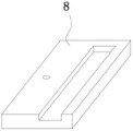
figure 4 is a perspective view of the connector tile of figure 1.
Reference numbers in the figures: 1. a base frame; 2. a support plate; 3. a work table; 4. installing a through groove; 5. a lifting screw; 6. a double-shaft motor; 7. a connecting rod; 8. a connector tile; 9. mounting a plate; 10. a placement groove; 11. rotating the disc; 12. a cavity; 13. rotating the motor; 14. a fixing plate; 15. a clamping plate; 16. clamping the screw rod; 17. a card slot; 18. a groove; 19. a clamping block; 20. connecting the through grooves; 21. a push rod.
Detailed Description
The utility model is further described with reference to the following figures and embodiments.
Referring to fig. 1-4, fig. 1 is a schematic front view of a working platform for electromechanical maintenance and convenient to move according to a preferred embodiment of the present invention; FIG. 2 is a front cross-sectional structural schematic view of the mounting plate shown in FIG. 1; FIG. 3 is a perspective view of the base frame shown in FIG. 1; figure 4 is a perspective view of the connector tile of figure 1. Electromechanical maintenance includes with work platform convenient to remove: a base frame 1; the two supporting plates 2 are fixedly arranged at the top of the base frame 1; the workbench 3 is fixedly arranged on the tops of the two supporting plates 2; the installation through groove 4 is formed in the top of the workbench 3; the two lifting screws 5 are rotatably mounted at the bottom of the workbench 3, and the bottom ends of the two lifting screws 5 extend into the base frame 1; the double-shaft motor 6 is fixedly arranged on the inner walls of the two sides of the base frame 1; the two connecting rods 7 are arranged in the base frame 1, and one ends, close to each other, of the two connecting rods 7 are fixedly connected with two rotating shafts of the double-shaft motor 6; the two connecting plates 8 are respectively and slidably mounted on the outer wall of one side, close to each other, of the two support plates 2, and the two connecting plates 8 are respectively in threaded connection with the two lifting screws 5; the mounting plate 9 is arranged above the base frame 1, and the mounting plate 9 is connected with the two connecting joint plates 8 in a sliding mode; a placing groove 10, wherein the placing groove 10 is formed on the top of the mounting plate 9; the rotating disc 11, the rotating disc 11 is installed on the inner wall of the bottom of the placing groove 10 in a rolling manner; the cavity 12 is formed in the mounting plate 9; the rotating motor 13 is fixedly installed on the inner wall of the bottom of the cavity 12, and a rotating shaft of the rotating motor 13 extends to the placing groove 10 and is fixedly connected with the bottom of the rotating disc 11; two fixing plates 14, wherein the two fixing plates 14 are fixedly arranged on the top of the rotating disc 11; the two clamping plates 15 are arranged on the top of the rotating disc 11 in a sliding mode; the two clamping screws 16 are respectively and rotatably mounted on the outer wall of one side, away from each other, of the two clamping plates 15, and the ends, away from each other, of the two clamping screws 16 respectively penetrate through the two fixing plates 14 and are respectively in threaded connection with the two fixing plates 14; the two clamping grooves 17 are formed in the outer walls of the two sides of the mounting plate 9; the two grooves 18 are formed in the inner walls of the two sides of the installation through groove 4; the two clamping blocks 19 are respectively installed on the inner walls of the bottoms of the two grooves 18 in a sliding mode; the two connecting through grooves 20 are formed in the top of the workbench 3, and the two connecting through grooves 20 are respectively communicated with the two grooves 18; the two pushing rods 21 are fixedly mounted at the tops of the two clamping blocks 19 respectively, and the two pushing rods 21 penetrate through the two connecting through grooves 20 respectively.
Two the bottom of lifting screw 5 is all fixed the cover and is equipped with first gear, two the one end that connecting rod 7 kept away from each other is all fixed the cover and is equipped with the second gear, first gear with the second gear meshing.
The top of the connecting plate 8 is provided with a threaded hole, and the lifting screw 5 penetrates through the threaded hole and is in threaded connection with the inner wall of the threaded hole.
The outer wall of one side of the base frame 1 is an inclined plane.
The bottom fixed mounting of mounting panel 9 has four universal wheels that are the rectangle and distribute.
The bottom fixed mounting of mounting panel 9 has two slides, two the spout has all been seted up at the top of linkage plate 8, the slide with spout sliding connection.
The working principle of the conveniently-moved working platform for electromechanical maintenance provided by the utility model is as follows:
when the device is used, electromechanical equipment to be maintained is placed on the rotating disc 11, then the two clamping screws 16 are respectively rotated to push the two clamping plates 15 to move towards the direction close to each other, the electromechanical equipment is clamped by the clamping plates 15, then the mounting plate 9 is pushed to move to the top of the base frame 1 by the four universal wheels, the two sliding plates at the bottom of the mounting plate 9 are slidably mounted in the sliding grooves at the tops of the two connecting plates 8, then the double-shaft motor 6 can be started to drive the two connecting rods 7 to rotate, the two lifting screws 5 are driven to rotate, the two connecting plates 8 are lifted, the mounting plate 9 and the electromechanical equipment are driven to lift, the mounting plate 9 enters the mounting through groove 4 and reaches a proper height, then the two pushing rods 21 push the two clamping blocks 19 to move towards the direction close to each other, and the two clamping blocks 19 enter the two clamping grooves 17, therefore, the fixing effect on the mounting plate 9 can be increased, the rotating motor 13 can be started to drive the rotating disc 11 to rotate, and accordingly the electromechanical equipment is driven to rotate, and maintenance personnel can maintain the electromechanical equipment more conveniently.
Compared with the related art, the conveniently-moved working platform for electromechanical maintenance provided by the utility model has the following beneficial effects:
through two clamping screw 16, two grip blocks 15 can be comparatively stable live electromechanical device centre gripping, through mounting panel 9, two link plate 8, biaxial motor 6, two connecting rods 7, and two lifting screw 5 can drive electromechanical device and rise to workstation 3, moreover, the operation is simple, need not artifical transport, operating personnel's physical power has been practiced thrift, and reduce the probability to electromechanical device's the damage that causes in the handling, through two catch bars 21, two fixture blocks 19 and two draw-in grooves 17 so alright increase the fixed action to mounting panel 9, and can drive electromechanical device through rotating motor 13 and rolling disc 11 and rotate, so can make things convenient for maintainer to maintain electromechanical device more.
The above description is only an embodiment of the present invention, and not intended to limit the scope of the present invention, and all modifications of equivalent structures and equivalent processes, which are made by using the contents of the present specification and the accompanying drawings, or directly or indirectly applied to other related technical fields, are included in the scope of the present invention.
Claims (6)
1. The utility model provides an electromechanical maintenance is with work platform convenient to remove which characterized in that includes:
a base frame;
the two supporting plates are fixedly arranged at the top of the base frame;
the workbench is fixedly arranged on the tops of the two supporting plates;
the mounting through groove is formed in the top of the workbench;
the two lifting screws are rotatably mounted at the bottom of the workbench, and the bottom ends of the two lifting screws extend into the base frame;
the double-shaft motor is fixedly arranged on the inner walls of the two sides of the base frame;
the two connecting rods are arranged in the base frame, and one ends, close to each other, of the two connecting rods are fixedly connected with the two rotating shafts of the double-shaft motor;
the two connecting plates are respectively and slidably mounted on the outer wall of one side, close to each other, of the two supporting plates, and the two connecting plates are respectively in threaded connection with the two lifting screws;
the mounting plate is arranged above the base frame and is in sliding connection with the two connecting plates;
the placing groove is formed in the top of the mounting plate;
the rotating disc is arranged on the inner wall of the bottom of the placing groove in a rolling mode;
the cavity is formed in the mounting plate;
the rotating motor is fixedly arranged on the inner wall of the bottom of the cavity, and a rotating shaft of the rotating motor extends to the placing groove and is fixedly connected with the bottom of the rotating disc;
the two fixed plates are fixedly arranged at the top of the rotating disc;
the two clamping plates are arranged on the top of the rotating disc in a sliding mode;
the two clamping screws are respectively and rotatably arranged on the outer wall of one side, away from each other, of the two clamping plates, and one ends, away from each other, of the two clamping screws respectively penetrate through the two fixing plates and are respectively in threaded connection with the two fixing plates;
the two clamping grooves are formed in the outer walls of the two sides of the mounting plate;
the two grooves are formed in the inner walls of the two sides of the mounting through groove;
the two clamping blocks are respectively installed on the inner walls of the bottoms of the two grooves in a sliding mode;
the two connecting through grooves are formed in the top of the workbench and are respectively communicated with the two grooves;
two catch bars, two the catch bar is fixed mounting respectively two the top of fixture block, and two the catch bar runs through two respectively connect logical groove.
2. The movable working platform for electromechanical maintenance according to claim 1, wherein a first gear is fixedly sleeved on each bottom end of the two lifting screws, a second gear is fixedly sleeved on each end of the two connecting rods away from each other, and the first gear is meshed with the second gear.
3. The movable working platform for electromechanical maintenance according to claim 1, wherein a threaded hole is formed at the top of the connecting plate, and the lifting screw penetrates through the threaded hole and is in threaded connection with the inner wall of the threaded hole.
4. The portable work platform for electromechanical maintenance according to claim 1, wherein an outer wall of one side of said base frame is formed as an inclined surface.
5. The movable workbench for electromechanical maintenance according to claim 1, wherein four universal wheels are fixedly mounted at the bottom of the mounting plate and distributed in a rectangular shape.
6. The movable working platform for electromechanical maintenance according to claim 1, wherein two sliding plates are fixedly mounted at the bottom of the mounting plate, sliding grooves are formed at the tops of the two connecting plates, and the sliding plates are slidably connected with the sliding grooves.
Priority Applications (1)
| Application Number | Priority Date | Filing Date | Title |
|---|---|---|---|
| CN202220460042.3U CN216731722U (en) | 2022-03-04 | 2022-03-04 | Convenient-to-move working platform for electromechanical maintenance |
Applications Claiming Priority (1)
| Application Number | Priority Date | Filing Date | Title |
|---|---|---|---|
| CN202220460042.3U CN216731722U (en) | 2022-03-04 | 2022-03-04 | Convenient-to-move working platform for electromechanical maintenance |
Publications (1)
| Publication Number | Publication Date |
|---|---|
| CN216731722U true CN216731722U (en) | 2022-06-14 |
Family
ID=81919319
Family Applications (1)
| Application Number | Title | Priority Date | Filing Date |
|---|---|---|---|
| CN202220460042.3U Expired - Fee Related CN216731722U (en) | 2022-03-04 | 2022-03-04 | Convenient-to-move working platform for electromechanical maintenance |
Country Status (1)
| Country | Link |
|---|---|
| CN (1) | CN216731722U (en) |
Cited By (1)
| Publication number | Priority date | Publication date | Assignee | Title |
|---|---|---|---|---|
| CN116713953A (en) * | 2023-07-31 | 2023-09-08 | 无锡机电高等职业技术学校 | An electrical maintenance operation platform for electromechanical equipment |
-
2022
- 2022-03-04 CN CN202220460042.3U patent/CN216731722U/en not_active Expired - Fee Related
Cited By (1)
| Publication number | Priority date | Publication date | Assignee | Title |
|---|---|---|---|---|
| CN116713953A (en) * | 2023-07-31 | 2023-09-08 | 无锡机电高等职业技术学校 | An electrical maintenance operation platform for electromechanical equipment |
Similar Documents
| Publication | Publication Date | Title |
|---|---|---|
| KR20240021643A (en) | Solar module disassembling automation system | |
| CN111746614A (en) | Auxiliary carrying device for loading and unloading equipment | |
| CN211169713U (en) | Auxiliary device for electromechanical installation | |
| CN110328488B (en) | Square water tank welding frock | |
| CN214093593U (en) | Maintenance device for construction machinery equipment | |
| CN114194800A (en) | Mechanical automatic gripping device for machining and manufacturing | |
| CN216780950U (en) | Screw detaching mechanism and detaching device | |
| CN212825425U (en) | A transport robot for cold storage | |
| CN217859765U (en) | Cold quick-witted auxiliary installation device of refrigerated container | |
| CN212793153U (en) | A positioning device for processing power take-off parts | |
| CN210150231U (en) | Tool for clamping light partition plate | |
| CN211004430U (en) | Construction machinery material lift | |
| CN221587842U (en) | Box nuclear waste container hoist | |
| CN211419345U (en) | Clamping lifting device applying plate carrying equipment | |
| CN211058337U (en) | Lifting construction mechanical equipment | |
| CN221540733U (en) | Oil press convenient to overhaul | |
| CN223002570U (en) | Adjustable multi-connected lifting appliance | |
| CN220165215U (en) | Automatic classifying, transporting and conveying machine | |
| CN222476054U (en) | Auxiliary installation device for indoor ceiling board | |
| CN221027421U (en) | Auxiliary fixing device for building electrical construction | |
| CN219535349U (en) | Ring main unit | |
| CN220428753U (en) | Trowelling device convenient to unload | |
| CN222450205U (en) | Frock is dismantled to retarber | |
| CN223313848U (en) | A motor tooling convenient for fixing | |
| CN213297278U (en) | Building fixed connection device capable of positioning |
Legal Events
| Date | Code | Title | Description |
|---|---|---|---|
| GR01 | Patent grant | ||
| GR01 | Patent grant | ||
| CF01 | Termination of patent right due to non-payment of annual fee | ||
| CF01 | Termination of patent right due to non-payment of annual fee |
Granted publication date: 20220614 |