CN216727143U - Efficient device for preventing steam material from flowing backwards through curing and degassing - Google Patents
Efficient device for preventing steam material from flowing backwards through curing and degassing Download PDFInfo
- Publication number
- CN216727143U CN216727143U CN202220265429.3U CN202220265429U CN216727143U CN 216727143 U CN216727143 U CN 216727143U CN 202220265429 U CN202220265429 U CN 202220265429U CN 216727143 U CN216727143 U CN 216727143U
- Authority
- CN
- China
- Prior art keywords
- curing
- steam
- degassing
- feeding
- kettle
- Prior art date
- Legal status (The legal status is an assumption and is not a legal conclusion. Google has not performed a legal analysis and makes no representation as to the accuracy of the status listed.)
- Active
Links
Images
Landscapes
- Physical Or Chemical Processes And Apparatus (AREA)
Abstract
The utility model relates to the technical field of chemical equipment, in particular to a high-efficiency device for preventing steam materials from flowing backwards in curing and degassing. According to the utility model, the primary condenser and the secondary condenser are arranged as a curing and degassing condensation mechanism and are matched with the pressure transmitter, the number of the condensers can be automatically adjusted according to the change of the air pressure in the curing kettle, the condensation treatment of steam is realized under the condition that the pressure in the curing kettle is not changed, the flow rate of the steam is controlled by the arranged induced draft fan and the vacuum pump under the adjustment of the frequency converter according to the air pressure value of the curing kettle, the efficient condensation of the steam in the curing kettle is realized, the operating efficiency of chemical curing and degassing equipment is improved, the problem of steam backflow caused by high steam material gas outlet rate and low subsequent treatment rate of the curing kettle is further avoided, and the device is suitable for popularization and use.
Description
Technical Field
The utility model relates to the technical field of chemical equipment, in particular to a high-efficiency device for preventing backflow of steam materials through curing and degassing.
Background
Most chemical industry curing degasification equipment that exists on the market at present, in the use, because the steam material exhaust rate of curing cauldron changes, the unable adjustment power in time of the treatment effeciency that leads to devices such as follow-up condensation, the condition of material refluence appears in the air feed mechanism that leads to curing cauldron after the air feed, consequently, provides a curing degasification high efficiency device of preventing steam material refluence to above-mentioned problem.
SUMMERY OF THE UTILITY MODEL
The utility model aims to provide a curing and degassing efficient device for preventing backflow of steam materials, a primary condenser and a secondary condenser are arranged as a curing and degassing condensation mechanism and matched with a pressure transmitter, the number of the condensers can be automatically adjusted according to the change of the air pressure in a curing kettle, condensation treatment on steam is realized under the condition that the pressure in the curing kettle is not changed, and an induced draft fan and a vacuum pump are arranged to control the flow rate of the steam according to the air pressure value of the curing kettle under the adjustment of a frequency converter, so that efficient condensation on the steam in the curing kettle is realized, the operation efficiency of chemical curing and degassing equipment is improved, the problem of steam backflow caused by high air outlet rate and low subsequent treatment rate of the steam materials in the curing kettle is further avoided, and the problem provided in the background technology is solved.
In order to achieve the purpose, the utility model provides the following technical scheme:
a high-efficient device of curing degasification anti-steam material refluence includes:
the device comprises a curing kettle, a heating mechanism is arranged at the bottom of the curing kettle, a feeding mechanism is arranged on the left side of the top of the curing kettle, and a detection mechanism is arranged on the curing kettle;
the condensation mechanism comprises a first-stage condenser and a second-stage condenser, wherein the feeding pipes of the first-stage condenser and the second-stage condenser are respectively connected with a feeding tee joint, the discharging pipes of the first-stage condenser and the second-stage condenser are respectively connected with a discharging tee joint, and after the feeding tee joint is connected with the curing kettle through a pipeline and the steam is discharged, the discharging tee joint is connected with a condensate tank through a pipeline;
the vacuum mechanism comprises a vacuum buffer tank and a vacuum pump connected with the vacuum buffer tank, and a feed inlet of the vacuum buffer tank is connected with an air outlet of the condensed liquid tank.
As a preferred scheme, still include control mechanism, control mechanism includes the control box, turns right from a left side on the inside bottom plate of control box and has set gradually relay group and converter group, is provided with the PLC controller on the right side inner wall of control box, and the control scheme of relay group and converter group connects the PLC controller respectively.
As a preferable scheme, the heating mechanism specifically includes an electric heater, and the electric heater is connected to a corresponding relay in the relay group through a line.
As a preferred scheme, the feeding mechanism specifically comprises a feeding pipe and a feeding valve arranged on the heating pipe, and the feeding valve is connected with a corresponding relay in the relay group through a line.
As an optimal scheme, the detection mechanism specifically comprises a radar level sensor and a pressure transmitter which are arranged on the top of the curing kettle, wherein the detection head extends into the curing kettle, and the radar level sensor and the pressure transmitter are respectively connected with a sensor interface of the PLC through lines.
As a preferred scheme, an induced draft fan is arranged on a pipeline of the curing kettle connected with the feeding tee joint, the induced draft fan is connected with corresponding frequency converters in the frequency converter group through lines, and the frequency converters connected with the induced draft fan are connected with corresponding relays in the relay group through lines.
As a preferred scheme, the pipelines of the feeding tee joint connected with the primary condenser and the secondary condenser are respectively provided with a switch valve, and the switch valves are connected with corresponding relays in the relay group through lines.
As a preferred scheme, the pipelines of the discharge tee joint connected with the primary condenser and the secondary condenser are respectively provided with a one-way valve.
As a preferred scheme, a driving motor of the vacuum pump is connected with a corresponding frequency converter in the frequency converter group through a line, and the frequency converter connected with the vacuum pump is connected with a corresponding relay in the relay group through a line.
According to the technical scheme provided by the utility model, the efficient device for preventing backflow of the steam material by curing and degassing has the beneficial effects that: through setting up one-level condenser and second grade condenser as the degasification condensation mechanism of curing, the use of cooperation pressure changer, can be according to the use number of the change automatically regulated condenser of curing cauldron internal gas pressure, realize carrying out condensation treatment to steam under the unchangeable circumstances of curing cauldron internal pressure, the draught fan and the vacuum pump of setting are according to the atmospheric pressure value control steam's of curing cauldron velocity of flow under the regulation of converter, the realization is to the high-efficient condensation of curing cauldron steam, the operating efficiency of chemical industry curing degasification equipment is improved, and then avoid because the problem of the low steam refluence that leads to of curing cauldron steam material air outlet rate height and follow-up processing speed, suitable using widely.
Drawings
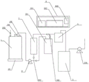
FIG. 1 is a schematic view of the overall structure of a device for preventing backflow of steam materials by curing and degassing.
In the figure: 1. a curing kettle; 101. a heating mechanism; 102. a feeding mechanism; 103. a radar level sensor; 104. a pressure transmitter; 2. an induced draft fan; 3. a first-stage condenser; 301. a secondary condenser; 302. a feeding tee joint; 303. a discharge tee joint; 4. a condensate tank; 5. a vacuum buffer tank; 501. a vacuum pump; 6. a control box; 601. a relay group; 602. a frequency converter group; 603. a PLC controller.
Detailed Description
In order to make the objects, technical solutions and advantages of the present invention more apparent, the present invention is described in further detail below with reference to the accompanying drawings and embodiments. It should be understood that the specific embodiments described herein are merely illustrative of the utility model and are not intended to limit the utility model.
It will be understood that when an element is referred to as being "secured to" or "disposed on" another element, it can be directly on the other element or be indirectly on the other element. When an element is referred to as being "connected to" another element, it can be directly connected to the other element or be indirectly connected to the other element.
In the description of the present invention, it is to be understood that the terms "length", "width", "upper", "lower", "front", "rear", "left", "right", "vertical", "horizontal", "top", "bottom", "inner", "outer", and the like, indicate orientations or positional relationships based on the orientations or positional relationships illustrated in the drawings, and are used merely for convenience in describing the present invention and for simplicity in description, and do not indicate or imply that the devices or elements referred to must have a particular orientation, be constructed in a particular orientation, and be operated, and thus, are not to be construed as limiting the present invention.
Furthermore, the terms "first", "second" and "first" are used for descriptive purposes only and are not to be construed as indicating or implying relative importance or implicitly indicating the number of technical features indicated. Thus, a feature defined as "first" or "second" may explicitly or implicitly include one or more of that feature. In the description of the present invention, "a plurality" means two or more unless specifically defined otherwise.
For better understanding of the above technical solutions, the following detailed descriptions will be provided in conjunction with the drawings and the detailed description of the present invention.
As shown in fig. 1, an embodiment of the present invention provides a high-efficiency device for preventing backflow of steam material in curing and degassing, comprising:
the control mechanism comprises a control box 6, a relay group 601 and a frequency converter group 602 are sequentially arranged on a bottom plate in the control box 6 from left to right, a PLC (programmable logic controller) 603 is arranged on the inner wall of the right side of the control box 6, and control circuits of the relay group 601 and the frequency converter group 602 are respectively connected with the PLC 603;
the device comprises a curing kettle 1, wherein a heating mechanism 101 is arranged at the bottom of the curing kettle 1, a feeding mechanism 102 is arranged on the left side of the top of the curing kettle 101, and a detection mechanism is arranged on the curing kettle 1;
the condensation mechanism comprises a first-stage condenser 3 and a second-stage condenser 301, feed pipes of the first-stage condenser 3 and the second-stage condenser 301 are respectively connected with a feed tee 302, discharge pipes of the first-stage condenser 3 and the second-stage condenser 301 are respectively connected with a discharge tee 303, and after the feed tee 302 is connected with steam of the curing kettle 101 through a pipeline and discharged, the discharge tee 303 is connected with a condensate tank 4 through a pipeline;
the vacuum mechanism comprises a vacuum buffer tank 5 and a vacuum pump 501 connected with the vacuum buffer tank 5, a feed inlet of the vacuum buffer tank 5 is connected with an air outlet of a condensed liquid tank 4, a driving motor of the vacuum pump 501 is connected with a corresponding frequency converter in a frequency converter group 602 through a line, and the frequency converter connected with the vacuum pump 501 is connected with a corresponding relay in a relay group 601 through a line.
In the above device, the heating mechanism 101 specifically includes an electric heater, and the electric heater is connected to a corresponding relay in the relay group 601 through a line.
In the above device, the feeding mechanism 102 specifically includes a feeding pipe and a feeding valve disposed on the heating pipe, and the feeding valve is connected to a corresponding relay in the relay group 601 through a line.
In the above device, the detection mechanism specifically includes radar level sensor 103 and pressure transmitter 104 arranged at the top of curing kettle 1, and the detection head extends into curing kettle 1, and radar level sensor 103 and pressure transmitter 104 are respectively connected with the sensor interface of PLC 603 through lines.
In the device, an induced draft fan 2 is arranged on a pipeline of the curing kettle 1 connected with the feeding tee 302, the induced draft fan 2 is connected with a corresponding frequency converter in the frequency converter group 602 through a line, and the frequency converter connected with the induced draft fan 2 is connected with a corresponding relay in the relay group 601 through a line.
In the device, the pipelines of the feeding tee joint 302 connected with the first-stage condenser 3 and the second-stage condenser 301 are respectively provided with a switch valve, the switch valves are connected with corresponding relays in the relay group 601 through lines, and the pipelines of the discharging tee joint 303 connected with the first-stage condenser 3 and the second-stage condenser 301 are respectively provided with a one-way valve.
According to the efficient device for curing and degassing and preventing backflow of steam materials, the primary condenser and the secondary condenser are arranged as a curing and degassing condensation mechanism and matched with the pressure transmitter, the number of the condensers can be automatically adjusted according to the change of the air pressure in the curing kettle, condensation treatment on steam is realized under the condition that the pressure in the curing kettle is not changed, the flow rate of the steam is controlled by the arranged induced draft fan and the arranged vacuum pump under the adjustment of the frequency converter according to the air pressure value of the curing kettle, efficient condensation on the steam in the curing kettle is realized, the operation efficiency of chemical curing and degassing equipment is improved, the problem of steam backflow caused by high steam material outlet rate and low subsequent treatment rate of the curing kettle is further avoided, and the device is suitable for popularization and use.
Embodiments of the utility model will be described in further detail below with reference to the following drawings:
referring to fig. 1, the device comprises a control box 6, a curing kettle 1, a first-stage condenser 3 and a second-stage condenser 301, a relay group 601 and a frequency converter group 602 are sequentially arranged on a bottom plate in the control box 6 from left to right, a PLC controller 603 is arranged on the inner wall of the right side of the control box 6, control circuits of the relay group 601 and the frequency converter group 602 are respectively connected with the PLC controller 603, a heating mechanism 101 is arranged at the bottom of the curing kettle 1, a feeding mechanism 102 is arranged at the left side of the top of the curing kettle 101, feed pipes of the first-stage condenser 3 and the second-stage condenser 301 are respectively connected with a feed tee 302, discharge pipes of the first-stage condenser 3 and the second-stage condenser 301 are respectively connected with a discharge tee 303, after steam of the feed tee 302 connected with the curing kettle 101 is discharged through a pipeline, the discharge tee 303 is connected with a condensate tank 4 through a pipeline, a radar level sensor 103 and a pressure transmitter 104 are arranged at the top of the curing kettle 1, a detection head extends into the curing kettle 1, the radar level sensor 103 and the pressure transmitter 104 are respectively connected with a sensor interface of the PLC 603 through lines, an induced draft fan 2 is arranged on a pipeline of the curing kettle 1 connected with the feeding tee 302, the induced draft fan 2 is connected with a corresponding frequency converter in the frequency converter group 602 through a line, the frequency converter connected with the induced draft fan 2 is connected with a corresponding relay in the relay group 601 through a line, switch valves are respectively arranged on pipelines of the feeding tee 302 connected with the primary condenser 3 and the secondary condenser 301, the switch valves are connected with the corresponding relay in the relay group 601 through a line, and check valves are respectively arranged on pipelines of the discharging tee 303 connected with the primary condenser 3 and the secondary condenser 301;
the device is characterized by further comprising a vacuum buffer tank 5 and a vacuum pump 501 connected with the vacuum buffer tank 5, wherein a feed inlet of the vacuum buffer tank 5 is connected with an air outlet of the condensed liquid tank 4, a driving motor of the vacuum pump 501 is connected with a corresponding frequency converter in the frequency converter group 602 through a line, and the frequency converter connected with the vacuum pump 501 is connected with a corresponding relay in the relay group 601 through a line.
The heating mechanism 101 specifically includes an electric heater, and the electric heater is connected to a corresponding relay in the relay group 601 through a line.
The feeding mechanism 102 specifically includes a feeding pipe and a feeding valve disposed on the heating pipe, and the feeding valve is connected to a corresponding relay in the relay group 601 through a line.
The working principle of the embodiment is as follows: through setting up one-level condenser and second grade condenser as the degasification condensation mechanism of curing, the use of cooperation pressure changer, can be according to the use number of the change automatically regulated condenser of curing cauldron internal gas pressure, realize carrying out the condensation processing to steam under the unchangeable circumstances of curing cauldron internal pressure, the draught fan and the vacuum pump of setting are according to the atmospheric pressure value control steam's of curing cauldron velocity of flow under the regulation of converter, the realization is to the high-efficient condensation of curing cauldron steam, the operating efficiency of chemical industry curing degasification equipment is improved, and then avoid because the problem of the low steam refluence that leads to of curing cauldron steam material air outlet rate height and subsequent processing speed.
Although embodiments of the present invention have been shown and described, it will be appreciated by those skilled in the art that changes, modifications, substitutions and alterations can be made in these embodiments without departing from the principles and spirit of the utility model, the scope of which is defined in the appended claims and their equivalents.
Claims (9)
1. The utility model provides a high-efficient device of steam material refluence is prevented in curing degasification which characterized in that: the method comprises the following steps:
the device comprises a curing kettle (1), wherein a heating mechanism (101) is arranged at the bottom of the curing kettle (1), a feeding mechanism (102) is arranged on the left side of the top of the curing kettle (1), and a detection mechanism is arranged on the curing kettle (1);
the condensation mechanism comprises a first-stage condenser (3) and a second-stage condenser (301), wherein feeding pipes of the first-stage condenser (3) and the second-stage condenser (301) are respectively connected with a feeding tee joint (302), discharging pipes of the first-stage condenser (3) and the second-stage condenser (301) are respectively connected with a discharging tee joint (303), the feeding tee joint (302) is connected with a condensate tank (4) through a pipeline after steam of the curing kettle (1) is discharged through the pipeline;
the vacuum mechanism comprises a vacuum buffer tank (5) and a vacuum pump (501) connected with the vacuum buffer tank (5), and a feed inlet of the vacuum buffer tank (5) is connected with an air outlet of the condensate tank (4).
2. The efficient device for preventing backflow of steam materials in curing and degassing as claimed in claim 1, wherein: still include control mechanism, control mechanism includes control box (6), turn right from a left side and set gradually relay group (601) and converter group (602) on the inside bottom plate of control box (6), be provided with PLC controller (603) on the right side inner wall of control box (6), PLC controller (603) are connected respectively to the control scheme of relay group (601) and converter group (602).
3. The efficient device for preventing backflow of steam materials in curing and degassing as claimed in claim 1, wherein: the heating mechanism (101) specifically comprises an electric heater, and the electric heater is connected with a corresponding relay in the relay group (601) through a line.
4. The efficient device for preventing backflow of steam materials in curing and degassing as claimed in claim 1, wherein: the feeding mechanism (102) specifically comprises a feeding pipe and a feeding valve arranged on the heating pipe, and the feeding valve is connected with a corresponding relay in the relay group (601) through a line.
5. The efficient device for preventing backflow of steam materials in curing and degassing as claimed in claim 1, wherein: detection mechanism is including setting up radar level sensor (103) and pressure transmitter (104) that stretch into curing kettle (1) inside at curing kettle (1) top detection head, radar level sensor (103) and pressure transmitter (104) are respectively through the sensor interface of line connection PLC controller (603).
6. The efficient device for preventing backflow of steam materials in curing and degassing as claimed in claim 1, wherein: be provided with draught fan (2) on the pipeline that feed tee bend (302) is connected in curing cauldron (1), draught fan (2) are through the converter that corresponds in line connection converter group (602), the converter that draught fan (2) are connected passes through the relay that corresponds in line connection relay group (601).
7. The efficient device for preventing backflow of steam materials in curing and degassing as claimed in claim 1, wherein: the pipeline that feeding tee bend (302) are connected one-level condenser (3) and second grade condenser (301) is provided with the ooff valve respectively, the ooff valve passes through the relay that corresponds in the line connection relay group (601).
8. The efficient device for preventing backflow of steam materials in curing and degassing as claimed in claim 1, wherein: and the pipelines of the discharge tee joint (303) connected with the primary condenser (3) and the secondary condenser (301) are respectively provided with a one-way valve.
9. The efficient device for preventing backflow of steam materials in curing and degassing as claimed in claim 1, wherein: the driving motor of the vacuum pump (501) is connected with a corresponding frequency converter in the frequency converter group (602) through a line, and the frequency converter connected with the vacuum pump (501) is connected with a corresponding relay in the relay group (601) through a line.
Priority Applications (1)
| Application Number | Priority Date | Filing Date | Title |
|---|---|---|---|
| CN202220265429.3U CN216727143U (en) | 2022-02-09 | 2022-02-09 | Efficient device for preventing steam material from flowing backwards through curing and degassing |
Applications Claiming Priority (1)
| Application Number | Priority Date | Filing Date | Title |
|---|---|---|---|
| CN202220265429.3U CN216727143U (en) | 2022-02-09 | 2022-02-09 | Efficient device for preventing steam material from flowing backwards through curing and degassing |
Publications (1)
| Publication Number | Publication Date |
|---|---|
| CN216727143U true CN216727143U (en) | 2022-06-14 |
Family
ID=81918168
Family Applications (1)
| Application Number | Title | Priority Date | Filing Date |
|---|---|---|---|
| CN202220265429.3U Active CN216727143U (en) | 2022-02-09 | 2022-02-09 | Efficient device for preventing steam material from flowing backwards through curing and degassing |
Country Status (1)
| Country | Link |
|---|---|
| CN (1) | CN216727143U (en) |
-
2022
- 2022-02-09 CN CN202220265429.3U patent/CN216727143U/en active Active
Similar Documents
| Publication | Publication Date | Title |
|---|---|---|
| CN201059546Y (en) | Device for recycling and transmitting device in enclosed type high-temperature condensate water and water collection pot | |
| CN111233060B (en) | Evaporator, vacuum degree, liquid level of evaporation kettle and water level detection control method of water tank | |
| CN101344245A (en) | Vapor recovery system | |
| CN215216190U (en) | Pipeline drainage system | |
| CN218511573U (en) | Negative pressure type heat exchange system | |
| CN203605745U (en) | Steam heat recovery device | |
| CN218581768U (en) | Vacuum pumping system for biodiesel rectification system | |
| CN217354498U (en) | Steam turbine exhaust steam condensing system based on plate heat exchanger | |
| CN213314895U (en) | Automatic buffer kettle system of pouring liquid | |
| CN222950647U (en) | An online oil discharge device for vacuum unit | |
| CN211176312U (en) | Exhaust gas pretreatment device | |
| CN210974053U (en) | Temperature control system of sewage treatment aerobic tank | |
| CN114856734B (en) | Steam turbine exhaust steam condensing system based on plate heat exchanger | |
| CN222938281U (en) | Exhaust steam condensing system of air separation device | |
| CN208980736U (en) | Reactor tank is used in a kind of processing of citric acid complex enzyme | |
| CN220853198U (en) | Improved rubber scorch retarder preparation condenser | |
| CN217179319U (en) | Steam condensate energy-saving device | |
| CN218673194U (en) | Evaporation condensation system capable of improving heat exchange efficiency | |
| CN220766955U (en) | Fermentation tank for sterilizing at high temperature and cooling gas | |
| CN207169677U (en) | Environment-friendly type reactor assembly | |
| CN215653866U (en) | Brand-new efficient medical intermediate rectification purification device | |
| CN207050497U (en) | Efficiently adjustable vacuum-control(led) system for power plant | |
| CN210512709U (en) | Condensate recovery system for steam leakage of steam turbine shaft seal | |
| CN112850828B (en) | Black water treatment system | |
| CN215783222U (en) | Valsartan intermediate production is with acidizing system |
Legal Events
| Date | Code | Title | Description |
|---|---|---|---|
| GR01 | Patent grant | ||
| GR01 | Patent grant |