CN216711349U - Hoisting beam for penetrating steel grating floor - Google Patents
Hoisting beam for penetrating steel grating floor Download PDFInfo
- Publication number
- CN216711349U CN216711349U CN202220189794.0U CN202220189794U CN216711349U CN 216711349 U CN216711349 U CN 216711349U CN 202220189794 U CN202220189794 U CN 202220189794U CN 216711349 U CN216711349 U CN 216711349U
- Authority
- CN
- China
- Prior art keywords
- steel
- hoisting
- main beam
- plate
- grating floor
- Prior art date
- Legal status (The legal status is an assumption and is not a legal conclusion. Google has not performed a legal analysis and makes no representation as to the accuracy of the status listed.)
- Active
Links
Images

Abstract
The utility model relates to the technical field of hoisting equipment, and discloses a hoisting beam for penetrating through a steel grating floor, which comprises a horizontally arranged main beam, wherein vertical columns are vertically arranged on the left side and the right side of the bottom end of the main beam; the upright column at one end is detachably connected with the main beam; a sliding steel plate is movably sleeved on the main beam, the bottom end of the sliding steel plate is connected with a connecting plate used for penetrating through the steel grating through a shackle, and a hanging part is arranged at the bottom end of the connecting plate; the utility model can improve the working efficiency, save the construction cost, prevent the situation that the sling is broken, improve the safety in the construction process, and has simple structure and strong practicability.
Description
Technical Field
The utility model relates to the technical field of hoisting equipment, in particular to a hoisting beam for a floor penetrating a steel grating.
Background
With the requirements of social development and sustainable production of process devices, more and more chemical enterprises select steel grating plates as construction materials of floor surfaces, and the materials have higher strength and beautiful appearance. The material is selected, so that the ventilation and drainage performance of the device can be greatly improved, and the corrosion of rainwater to the device can be effectively reduced; because the steel grating is formed by assembling blocks, the disassembly is convenient, space is provided for the replacement of large-scale equipment and pipelines in the future, and the practicability is strong. In the normal construction and maintenance process, a large amount of floor-penetrating hoisting operation can be performed. The conventional method is to set up a hoisting frame and then carry out hoisting operation, but the method wastes a large amount of manpower and material resources, and in addition, some positions have limited space, the hoisting frame cannot be set up, so that great inconvenience is brought to operation. In addition, when the sling of the existing hoisting tool is used and passes through a steel grating for use, the sling is in contact with a grating of the steel grating to generate friction, and the sling has the risk of generating fracture due to friction, so that the potential safety hazard in the construction process is increased.
SUMMERY OF THE UTILITY MODEL
The utility model aims to provide a hoisting beam for a floor penetrating through a steel grating, which not only can improve the working efficiency and save the construction cost, but also can prevent the situation that a sling is broken and improve the safety in the construction process, and has simple structure and strong practicability.
The utility model adopts the following technical scheme:
a hoisting beam penetrating through a steel grating floor comprises a horizontally arranged main beam, wherein upright columns are vertically arranged on the left side and the right side of the bottom end of the main beam; wherein the upright column at one end is detachably connected with the main beam; the movable sleeve is equipped with the sliding steel board on the girder, and the bottom of sliding steel board is connected with the connecting plate that is used for running through the steel grating through the shackle, and the connecting plate bottom is provided with the portion of articulate.
The bottom end of each upright post is provided with a bottom plate.
The bottom plate is square.
And reinforcing rib plates are arranged between the bottom plate and the upright posts.
The main beam and the upright post are all H-shaped steel; the sliding steel plate is provided with an H-shaped sliding groove.
The top end of the stand column detachably connected with the main beam is provided with a support plate, a positioning plate is arranged on the support plate, and a bolt for positioning and fixing the main beam is arranged on the positioning plate.
The locating plate setting both sides around the backup pad top, and every side all is provided with two.
Compared with the prior art, the utility model has the beneficial effects that: the utility model greatly improves the construction efficiency of small hoisting in the device and saves a large amount of construction cost; the embarrassment that conventional hoisting operation cannot be carried out due to the fact that construction space is narrow in the device is improved, meanwhile, the connecting plate is inserted below the steel grating, the situation that friction fracture risks are caused due to the fact that a sling is directly contacted with the steel grating can be avoided, and safety risks are greatly reduced; in addition, the utility model can be used on floors of steel-penetrating grating plates and concrete floors with holes, and has wide application range and strong practicability.
Furthermore, one of the upright columns at the bottom end of the main beam is detachably connected with the main beam, so that the distance between the two main beams can be conveniently adjusted, different spans of steel structures in construction sites can be met, the application range of the utility model is expanded, and the practicability of the utility model is improved; the sliding connection of sliding steel plate and girder is convenient for adjust hoisting point position according to the demand, promotes the stability of hoist and mount roof beam when hoist and mount operation.
Drawings
FIG. 1 is a schematic structural view of the present invention;
fig. 2 is a side view of the sliding steel plate of the present invention.
Detailed Description
The utility model will now be described more fully hereinafter with reference to the accompanying drawings and examples in which:
as shown in fig. 1 to 2, the hoisting beam for a floor penetrating through a steel grating comprises a horizontally arranged main beam 1, wherein upright posts 2 are vertically arranged on the left side and the right side of the bottom end of the main beam 1; wherein the upright post 2 at one end is detachably connected with the main beam 1; the distance between the two upright posts 2 can be adjusted conveniently, so that different spans of steel structures on construction sites can be met, the application range of the utility model is expanded, and the practicability of the utility model is improved; h-shaped section steel is preferably adopted for the upright posts 2 and the main beam 1 so as to improve the integral structural strength of the hoisting beam; the top end of an upright post 2 detachably connected with a main beam 1 is provided with a support plate 3, the front end and the rear end of the support plate 3 are provided with two positioning plates 4, each end of each positioning plate 4 is provided with two positioning plates 4, the positioning plates 4 are preferably arranged in an inverted L shape, the bottom end of each positioning plate 4 is spaced from the top end of a lower flange plate of the main beam 1, so that the upright post 2 can be conveniently moved and adjusted along the main beam 1, and the positioning plates 4 are provided with bolts for positioning and fixing the main beam 1; after the stand 2 that can dismantle with girder 1 and be connected adjusts in place, screw up the bolt and make it support tightly at girder 1 bottom flange board top can, simple structure, it is easy and simple to handle, the practicality is strong.
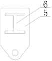
A sliding steel plate 5 is movably sleeved on the main beam 1, and an H-shaped sliding chute 6 is arranged on the sliding steel plate 5; the sliding arrangement of the sliding steel plate 5 and the main beam 1 facilitates the adjustment of the lifting point position according to requirements and improves the stability of the lifting beam during lifting operation. The bottom end of the sliding steel plate 5 is connected with a connecting plate 8 used for penetrating through the steel grating through a shackle 7, and the bottom end of the connecting plate 8 is provided with a hanging part 9; the hanging part 9 is used for being connected with hoisting equipment.
Furthermore, a square bottom plate 10 is arranged at the bottom end of each upright post 2 to increase the contact area between the hoisting beam and the supporting surface and improve the stability of the whole hoisting beam during hoisting construction; a reinforcing rib plate 11 is arranged between each bottom plate 10 and the upright post 2 to enhance the structural strength of the hoisting beam.
The application process of the utility model comprises the following steps: firstly, placing a bottom plate 10 of a hoisting beam on a steel structure or other supporting surfaces; then adjusting the sliding steel plate 5 to be positioned at the hoisting position; finally, inserting the connecting plate 8 into the gap of the steel grating plate to enable the hanging part 9 at the bottom end of the connecting plate 8 to be positioned below the bottom surface of the steel grating plate, and connecting the hoisting equipment with the hanging part 9 to perform hoisting operation; because the hoisting equipment is arranged below the steel grating and the connecting plate 8 only plays a supporting role during hoisting operation, continuous or large abrasion cannot be generated between the steel grating and the connecting plate 8, the condition that a sling is broken due to friction when the sling is used for hoisting can be avoided, and the safety in the construction process is ensured; the hoisting frame is simple in structure, convenient to use, fast to operate, low in cost and high in practicability, and large manpower and material resources are not needed for building the hoisting frame.
Claims (7)
1. The utility model provides a wear hoist and mount roof beam of steel grating floor which characterized in that: the device comprises a horizontally arranged main beam, wherein upright columns are vertically arranged on the left side and the right side of the bottom end of the main beam; wherein the upright column at one end is detachably connected with the main beam; the movable sleeve is equipped with the sliding steel board on the girder, and the bottom of sliding steel board is connected with the connecting plate that is used for running through the steel grating through the shackle, and the connecting plate bottom is provided with the portion of articulate.
2. The hoisting beam of the steel-penetrating grating floor as claimed in claim 1, wherein: the bottom end of each upright post is provided with a bottom plate.
3. The hoisting beam of the steel-penetrating grating floor as claimed in claim 2, wherein: the bottom plate is square.
4. The hoisting beam of the steel-penetrating grating floor as claimed in claim 3, wherein: and reinforcing rib plates are arranged between the bottom plate and the upright posts.
5. The hoisting beam of the steel-penetrating grating floor as claimed in claim 1, wherein: the main beam and the upright post are all H-shaped steel; the sliding steel plate is provided with an H-shaped sliding groove.
6. The hoisting beam of the steel-penetrating grating floor as claimed in claim 5, wherein: can dismantle with the girder and be connected stand top be provided with the backup pad, be provided with the locating plate in the backup pad, be provided with on the locating plate and carry out the bolt of fixed location to the girder.
7. The hoisting beam of the steel-penetrating grating floor as claimed in claim 6, wherein: the locating plate setting both sides around the backup pad top, and every side all is provided with two.
Priority Applications (1)
| Application Number | Priority Date | Filing Date | Title |
|---|---|---|---|
| CN202220189794.0U CN216711349U (en) | 2022-01-24 | 2022-01-24 | Hoisting beam for penetrating steel grating floor |
Applications Claiming Priority (1)
| Application Number | Priority Date | Filing Date | Title |
|---|---|---|---|
| CN202220189794.0U CN216711349U (en) | 2022-01-24 | 2022-01-24 | Hoisting beam for penetrating steel grating floor |
Publications (1)
| Publication Number | Publication Date |
|---|---|
| CN216711349U true CN216711349U (en) | 2022-06-10 |
Family
ID=81874161
Family Applications (1)
| Application Number | Title | Priority Date | Filing Date |
|---|---|---|---|
| CN202220189794.0U Active CN216711349U (en) | 2022-01-24 | 2022-01-24 | Hoisting beam for penetrating steel grating floor |
Country Status (1)
| Country | Link |
|---|---|
| CN (1) | CN216711349U (en) |
-
2022
- 2022-01-24 CN CN202220189794.0U patent/CN216711349U/en active Active
Similar Documents
| Publication | Publication Date | Title |
|---|---|---|
| CN105587097A (en) | Ground aerial structure capable of being leveled | |
| CN213329955U (en) | Flower basket diagonal rod type overhanging scaffold | |
| CN216711349U (en) | Hoisting beam for penetrating steel grating floor | |
| CN201506692U (en) | Roofing steel structure simple lifting device and installation structure thereof | |
| CN204400502U (en) | Bottle gouard moved by hands support | |
| CN106320699A (en) | Quick disassembling and assembling method for truss type formwork bracket system | |
| CN213484787U (en) | Photovoltaic power generation board mounting and supporting structure with suspended steel beam foundation | |
| CN214575651U (en) | Adjustable steel bar truss floor support plate construction supporting device | |
| CN212201279U (en) | Assembled adjustable steel bar truss floor bearing plate supporting structure | |
| CN209941512U (en) | Supporting shear part for lower cross beam of inclined tower of cable-stayed bridge | |
| CN110593299A (en) | Leveling device for embedded part of transformer | |
| CN101158227B (en) | Externally-hanging type exterior wall scaffold | |
| CN218668474U (en) | Basket type overhanging bearing frame | |
| CN212613030U (en) | Variable steel frame for super high-rise building construction | |
| CN212836633U (en) | Be used for encorbelmenting portable spud pile of I-steel | |
| CN205153124U (en) | Steel construction building bearing axle | |
| CN218117153U (en) | Elevator shaft operating platform | |
| CN211368613U (en) | Gate pier bracket formwork braced system that encorbelments | |
| CN216476314U (en) | Assembly type formwork system of cast-in-place plate of steel structure building | |
| CN210264071U (en) | Movable PC component production workshop | |
| CN211895777U (en) | High-strength concrete slab mounting system adopting sliding rails | |
| CN220747233U (en) | Steel construction factory building that can install fast | |
| CN204676439U (en) | A kind of Bailey beam formula can be hung by supertronic tower top | |
| CN201121408Y (en) | Externally hanging type exterior wall scaffold | |
| CN113789958B (en) | Steel construction composite floor hangs mould structure |
Legal Events
| Date | Code | Title | Description |
|---|---|---|---|
| GR01 | Patent grant | ||
| GR01 | Patent grant |