CN216709322U - Luggage barrow - Google Patents
Luggage barrow Download PDFInfo
- Publication number
- CN216709322U CN216709322U CN202220112125.3U CN202220112125U CN216709322U CN 216709322 U CN216709322 U CN 216709322U CN 202220112125 U CN202220112125 U CN 202220112125U CN 216709322 U CN216709322 U CN 216709322U
- Authority
- CN
- China
- Prior art keywords
- pipe
- hinged
- cross
- locking
- underframe
- Prior art date
- Legal status (The legal status is an assumption and is not a legal conclusion. Google has not performed a legal analysis and makes no representation as to the accuracy of the status listed.)
- Active
Links
- 238000004806 packaging method and process Methods 0.000 abstract description 4
- 210000000245 forearm Anatomy 0.000 description 6
- 238000000034 method Methods 0.000 description 5
- XEEYBQQBJWHFJM-UHFFFAOYSA-N Iron Chemical compound [Fe] XEEYBQQBJWHFJM-UHFFFAOYSA-N 0.000 description 2
- 230000000712 assembly Effects 0.000 description 2
- 238000000429 assembly Methods 0.000 description 2
- 238000012986 modification Methods 0.000 description 2
- 230000004048 modification Effects 0.000 description 2
- 229910000838 Al alloy Inorganic materials 0.000 description 1
- 229910000640 Fe alloy Inorganic materials 0.000 description 1
- 239000000956 alloy Substances 0.000 description 1
- 238000010586 diagram Methods 0.000 description 1
- 230000000694 effects Effects 0.000 description 1
- 230000005484 gravity Effects 0.000 description 1
- 239000000463 material Substances 0.000 description 1
- 230000000750 progressive effect Effects 0.000 description 1
Images



Landscapes
- Handcart (AREA)
Abstract
The utility model discloses a luggage van, which comprises a main body frame and wheels arranged on the main body frame; the main body frame includes: the front arm pipe and the rear arm pipe frame are positioned on the upper layer; the front underframe and the rear underframe are positioned at the lower layer and hinged, and wheels are arranged on the front underframe; a front connecting pipe; a foot tube; one end of the first cross pipe is hinged with the front arm pipe, and the other end of the first cross pipe is hinged with the foot pipe and the rear underframe; one end of the second cross pipe is hinged with the rear arm pipe frame, and the other end of the second cross pipe is hinged with the front connecting pipe and the front underframe; and the first cross pipe is arranged to cross the second cross pipe, and is hinged at the cross point. The luggage barrow provided by the utility model can be folded by folding the front connecting pipe and the front underframe, so that the whole luggage barrow is convenient to operate, the folded packaging volume is small, and the transportation cost is low.
Description
Technical Field
The utility model relates to the field of outdoor equipment, in particular to a luggage van.
Background
Because of the outdoor fishing supplies and equipment in foreign markets, luggage trucks are needed to transport the supplies and equipment to fishing sites in places where some trucks cannot reach.
In the prior art, the luggage barrow mainly takes disassembly and assembly as a main part, and all parts are assembled before use; in addition, the main body frame of the existing luggage barrow is large and cannot be folded, or the luggage barrow is large in packaging volume after being disassembled, so that the transportation cost is increased, and the luggage barrow is inconvenient to install at the later stage; when the parts are assembled, the gravity center is higher and the carrying space is smaller.
Therefore, how to improve the convenience of the luggage barrow in use and transportation is a technical problem which needs to be solved by the technicians in the field at present.
SUMMERY OF THE UTILITY MODEL
The utility model aims to provide a luggage van which can be quickly folded, effectively improves the disassembly and assembly convenience of the luggage van, and has small transportation volume.
In order to achieve the purpose, the utility model provides the following technical scheme:
a luggage van includes a main body frame and a wheel mounted on the main body frame; the main body frame includes:
the front arm pipe and the rear arm pipe frame are positioned on the upper layer;
the front underframe and the rear underframe are positioned at the lower layer and hinged, and the wheels are arranged on the front underframe;
the front connecting pipe is hinged between the front arm pipe and the front underframe;
the foot pipe is hinged between the rear arm pipe frame and the rear underframe;
one end of the first cross pipe is hinged with the front arm pipe, and the other end of the first cross pipe is hinged with the foot pipe and the rear underframe;
one end of the second cross pipe is hinged with the rear arm pipe frame, and the other end of the second cross pipe is hinged with the front connecting pipe and the front underframe; and the first cross pipe and the second cross pipe are arranged to cross each other, and are hinged at the cross point.
Preferably, the number of the first cross pipe, the second cross pipe, the locking assembly, the front connecting pipe and the foot pipe is two, and the first cross pipe, the second cross pipe, the locking assembly, the front connecting pipe and the foot pipe are respectively distributed in a left-right symmetrical mode relative to the main body frame.
Preferably, the handrail is arranged on the rear arm pipe frame; the handrail with can dismantle the connection through fixed hand wheel between the back arm pipe support.
Preferably, the front bumper is hinged to the forearm pipe and can be bent to fit with the forearm pipe.
Preferably, the front end of the front underframe is also provided with a baffle pipe, and the baffle pipe is fixedly connected with the front connecting pipe.
Preferably, the bottom of the foot pipe is provided with a foot plate.
Preferably, the first cross pipe and the leg pipe, the first cross pipe and the front arm pipe, the second cross pipe and the rear arm pipe support, and the second cross pipe and the front connecting pipe are hinged by connecting pieces, and the connecting pieces are in a corner shape.
Preferably, the folding table further comprises a locking assembly arranged obliquely and positioned between the front connecting pipe and the front underframe for folding the front connecting pipe and the front underframe
Preferably, the locking assembly comprises a first locking pipe, a second locking pipe and a locking part hinged between the first locking pipe and the second locking pipe, one end of the first locking pipe, which is far away from the locking part, is hinged to the front chassis, and one end of the second locking pipe, which is far away from the locking part, is hinged to the front connecting pipe.
Preferably, the surface of the locking part is provided with a pull ring.
The luggage van provided by the utility model comprises a main body frame and wheels arranged on the main body frame; the main body frame includes: the front arm pipe and the rear arm pipe frame are positioned on the upper layer; the front underframe and the rear underframe are positioned at the lower layer and hinged, and the wheels are arranged on the front underframe; the front connecting pipe is hinged between the front arm pipe and the front underframe; the foot tube is hinged between the rear arm tube frame and the rear underframe; one end of the first cross pipe is hinged with the front arm pipe, and the other end of the first cross pipe is hinged with the foot pipe and the rear underframe; one end of the second cross pipe is hinged with the rear arm pipe frame, and the other end of the second cross pipe is hinged with the front connecting pipe and the front underframe; and the first cross tube is arranged to cross the second cross tube, and is hinged at the cross point. The luggage barrow provided by the utility model can be folded by folding the front connecting pipe and the front underframe, so that the whole luggage barrow is convenient to operate, the folded packaging volume is small, and the transportation cost is low.
Drawings
In order to more clearly illustrate the embodiments of the present invention or the technical solutions in the prior art, the drawings used in the embodiments or the prior art descriptions will be briefly described below, it is obvious that the drawings in the following description are only some embodiments of the present invention, and other drawings can be obtained by those skilled in the art without creative efforts.
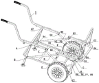
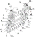
FIG. 1 is a schematic structural view of one embodiment of a luggage cart according to the present invention;
FIG. 2 is a schematic illustration of the position of the hinges of the luggage cart of FIG. 1;
FIG. 3 is a schematic view of the front rail of the luggage cart shown in FIG. 1;
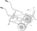
fig. 4 is a schematic structural view of the luggage van shown in fig. 1 during a folding process;
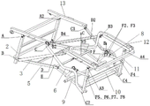
FIG. 5 is a schematic view of the luggage cart of FIG. 1 shown in an operational configuration with the armrest and wheels removed;
FIG. 6 is an enlarged schematic view of a locking member of the luggage cart of FIG. 5;
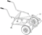
FIG. 7 is a schematic illustration of the luggage cart of FIG. 1 shown in a collapsed configuration;
FIG. 8 is a schematic illustration of the hinge position of the luggage cart of FIG. 1 after folding;
wherein: an armrest-1; fixing a hand wheel-1-1; a pin tube-2; a first cross tube-3; a baseboard-4; a rear chassis-5; a second cross-tube-6; a wheel-7; a locking member-8; a front chassis-9; a baffle pipe-9-1; a front connecting pipe-10; a forearm tube-11; front gear-12; rear arm pipe frame-13.
Detailed Description
The core of the utility model is to provide a luggage van which can be folded quickly, thus effectively improving the convenience of disassembly and assembly and having small transportation volume.
The technical solutions in the embodiments of the present invention will be clearly and completely described below with reference to the drawings in the embodiments of the present invention, and it is obvious that the described embodiments are only a part of the embodiments of the present invention, and not all of the embodiments. All other embodiments, which can be derived by a person skilled in the art from the embodiments given herein without making any creative effort, shall fall within the protection scope of the present invention.
Referring to fig. 1 to 8, fig. 1 is a schematic structural diagram of a luggage cart according to an embodiment of the present invention; FIG. 2 is a schematic illustration of the position of the hinges of the luggage cart of FIG. 1; FIG. 3 is a schematic view of the front rail of the luggage cart shown in FIG. 1; fig. 4 is a schematic structural view of the luggage van shown in fig. 1 during a folding process; FIG. 5 is a schematic view of the luggage cart of FIG. 1 shown in an operational configuration with the armrest and wheels removed; FIG. 6 is an enlarged schematic view of a locking member of the luggage cart of FIG. 5; FIG. 7 is a schematic illustration of the luggage cart of FIG. 1 shown in a collapsed configuration; fig. 8 is a schematic view of the folded hinge position of the luggage van of fig. 1.
In this embodiment, the luggage van includes a main body frame and a wheel 7 mounted on the main body frame; the main body frame includes: a front arm pipe 11 and a rear arm pipe frame 13 which are positioned at the upper layer; the front underframe 9 and the rear underframe 5 are positioned at the lower layer, the front underframe 9 is hinged with the rear underframe 5, and the wheels 7 are arranged on the front underframe 9; the front connecting pipe 10 is hinged between the front arm pipe 11 and the front underframe 9; the foot tube 2 is hinged between the rear arm tube frame 13 and the rear underframe 5; one end of the first cross pipe 3 is hinged with the front arm pipe 11, and the other end of the first cross pipe 3 is hinged with the foot pipe 2 and the rear underframe 5; one end of the second cross pipe 6 is hinged with the rear arm pipe frame 13, and the other end of the second cross pipe 6 is hinged with the front connecting pipe 10 and the front underframe 9; and, the first cross tube 3 is arranged to cross the second cross tube 6, and is hinged at the crossing point.
According to the luggage van provided by the utility model, the front connecting pipe 10 and the front underframe 9 are folded by using the locking assembly, so that the whole luggage van is folded, the operation is convenient, the folded packaging volume is small, and the transportation cost is low.
In addition to the above embodiments, the number of the first cross pipe 3, the second cross pipe 6, the locking member, the front connection pipe 10, and the leg pipe 2 is two, and they are distributed symmetrically with respect to the main body frame.
In addition to the above embodiments, the present invention further includes a handrail 1, the handrail 1 being mounted on a rear arm pipe frame 13; the handrail 1 is detachably connected with the rear arm pipe frame 13 through a fixed hand wheel 1-1.
In addition to the above embodiments, the front bumper 12 is further included, the front bumper 12 is hinged to the forearm tube 11, and the front bumper 12 can be bent to fit with the forearm tube 11 to retract the front bumper 12.
Specifically, as shown in fig. 3, the process of rapidly folding the front rail 12 is as follows: the folded state is achieved by rotating the hinge G and the hinge G2 at the connection between the forearm tube 11 and the front rail 12 in the direction of rotation, i.e., direction a, and the unfolded state is achieved otherwise. The above steps can be completed before the main body frame is furled, or can be completed in the process of furling the main body frame or after furling the main body frame.
On the basis of the above embodiments, the front end of the front chassis 9 is further provided with the baffle pipe 9-1, the baffle pipe 9-1 is fixedly connected with the front connecting pipe 10 to form a front chassis baffle frame together, and the arrangement of the baffle pipe 9-1 can not only increase the strength and stability of the whole main body frame, but also prevent goods from falling off from the front end of the main body frame.
In addition to the above embodiments, a foot plate 4 is provided at the bottom of the leg tube 2 to support on the ground.
On the basis of the above embodiments, the upper parts of the rear arm pipe frame 13 and the front arm pipe 11 are provided with holding handles, and after the luggage van is folded, the luggage van can be conveniently taken by holding the handles.
In addition to the above embodiments, the first cross pipe 3 and the leg pipe 2, the first cross pipe 3 and the front arm pipe 11, the second cross pipe 6 and the rear arm pipe frame 13, and the second cross pipe 6 and the front connection pipe 10 are hinged by the joint pieces, and the joint pieces are in the shape of corners.
On the basis of the above embodiments, a locking assembly, preferably arranged obliquely, is further included, and the locking assembly is hinged between the front connecting pipe 10 and the front chassis 9 for folding the front connecting pipe 10 and the front chassis 9. Preferably, the number of the locking assemblies is two, and the locking assemblies are distributed in a left-right symmetrical mode relative to the main body frame.
Further, the locking subassembly, including first locking pipe, second locking pipe and articulate in locking part 8 between first locking pipe and second locking pipe, the one end that locking part 8 was kept away from to first locking pipe is articulated with preceding chassis 9, and the one end that locking part 8 was kept away from to second locking pipe is articulated with preceding connecting pipe 10. Specifically, locking part 8 is cylindricly, and locking part 8 is inside to be equipped with two pin joints, connects first locking pipe, second locking pipe respectively, and locking part 8's both ends bottom all is equipped with dodges the groove for dodge when first locking pipe, second locking pipe buckle, when locking part 8 pushes down, first locking pipe, second locking pipe all incline to set up, can extrude locking part 8 each other, realize the locking purpose.
On the basis of each embodiment, the surface of the locking part 8 is provided with a pull ring, so that an operator can conveniently lift the pull ring, and further pull the locking part 8, and the unlocking purpose is realized.
In addition to the above embodiments, the luggage cart is made of an iron or aluminum alloy material, but may be made of other materials with light weight and high strength.
Specifically, as shown in fig. 5, the operation mode of the fast folding structure of the main frame is as follows:
the luggage barrow completes unlocking and is locked by exerting pulling force in the direction B through the locking part 8, the hinge F2, the hinge F3 and the hinge F4 on the first locking pipe and the second locking pipe, and the hinge F5, the hinge F6, the hinge F7 and the hinge F8; the hinges F5, F6, F7 and F8 are symmetrically distributed with the hinges F, F2, F3 and F4; after unlocking, force in the direction of C is applied to the rear underframe 5 and the front underframe 9, and the leg tube 2, the front connecting tube 10, the first cross tube 3 and the second cross tube 6 are linked by the quadrilateral mechanism through the hinge a, the hinge a2, the hinge A3, the hinge a4, the hinge B2, the hinge B3, the hinge B4, the hinge C2, the hinge C3, the hinge C4, the hinge D2, the hinge E and the hinge E2, so that the main body frame of the luggage van is completely folded, and otherwise, the luggage van is unfolded. Of course, the main body frame may be caused to produce a linking effect by driving other members.
The embodiments in the present description are described in a progressive manner, each embodiment focuses on differences from other embodiments, and the same and similar parts among the embodiments are referred to each other.
The luggage van provided by the utility model is described in detail above. The principles and embodiments of the present invention are explained herein using specific examples, which are presented only to assist in understanding the method and its core concepts. It should be noted that, for those skilled in the art, it is possible to make various improvements and modifications to the present invention without departing from the principle of the present invention, and those improvements and modifications also fall within the scope of the claims of the present invention.
Claims (10)
1. A luggage cart comprising a main body frame and a wheel (7) mounted on the main body frame; characterized in that, the main body frame includes:
a front arm pipe (11) and a rear arm pipe frame (13) which are positioned at the upper layer;
the front chassis (9) and the rear chassis (5) are positioned at the lower layer, the front chassis (9) is hinged with the rear chassis (5), and the wheels (7) are installed on the front chassis (9);
the front connecting pipe (10) is hinged between the front arm pipe (11) and the front underframe (9);
the foot pipe (2) is hinged between the rear arm pipe frame (13) and the rear underframe (5);
one end of the first cross pipe (3) is hinged with the front arm pipe (11), and the other end of the first cross pipe (3) is hinged with the foot pipe (2) and the rear underframe (5);
one end of the second cross pipe (6) is hinged with the rear arm pipe frame (13), and the other end of the second cross pipe (6) is hinged with the front connecting pipe (10) and the front underframe (9); and the first cross pipe (3) and the second cross pipe (6) are arranged crosswise and hinged at the crossing point.
2. The luggage van of claim 1, wherein the number of the first cross pipe (3), the second cross pipe (6), the front connection pipe (10), and the foot pipe (2) is two, and each of the two is distributed symmetrically with respect to the main body frame.
3. The luggage cart of claim 1, further comprising an armrest (1), said armrest (1) being mounted on said rear arm tube carrier (13); the handrail (1) and the rear arm pipe support (13) are detachably connected through a fixed hand wheel (1-1).
4. The luggage van of claim 1, further comprising a front bumper (12), wherein the front bumper (12) is hinged to the front arm tube (11), and wherein the front bumper (12) is foldable to fit the front arm tube (11).
5. The luggage van of claim 1, wherein a baffle pipe (9-1) is further provided at the front end of the front chassis (9), and the baffle pipe (9-1) is fixedly connected with the front connecting pipe (10).
6. Luggage van according to claim 1, characterized in that the bottom of the foot tube (2) is provided with a foot plate (4).
7. Luggage van according to claim 1, characterized in that the first cross pipe (3) and the foot pipe (2), the first cross pipe (3) and the front arm pipe (11), the second cross pipe (6) and the rear arm pipe frame (13) and the second cross pipe (6) and the front connection pipe (10) are hinged with a gusset, which is in the shape of a corner.
8. The luggage van of any of claims 1 to 7, further comprising a locking assembly arranged obliquely and hinged between the front connection pipe (10) and the front chassis (9) for folding the front connection pipe (10) and the front chassis (9).
9. Luggage van according to claim 8, wherein the locking assembly comprises a first locking tube, a second locking tube and a locking member (8) hinged between the first locking tube and the second locking tube, wherein one end of the first locking tube, which is far away from the locking member (8), is hinged with the front chassis (9), and one end of the second locking tube, which is far away from the locking member (8), is hinged with the front connecting tube (10).
10. Luggage van according to claim 9, characterized in that the surface of the locking member (8) is provided with a pull ring.
Priority Applications (1)
| Application Number | Priority Date | Filing Date | Title |
|---|---|---|---|
| CN202220112125.3U CN216709322U (en) | 2022-01-17 | 2022-01-17 | Luggage barrow |
Applications Claiming Priority (1)
| Application Number | Priority Date | Filing Date | Title |
|---|---|---|---|
| CN202220112125.3U CN216709322U (en) | 2022-01-17 | 2022-01-17 | Luggage barrow |
Publications (1)
| Publication Number | Publication Date |
|---|---|
| CN216709322U true CN216709322U (en) | 2022-06-10 |
Family
ID=81890777
Family Applications (1)
| Application Number | Title | Priority Date | Filing Date |
|---|---|---|---|
| CN202220112125.3U Active CN216709322U (en) | 2022-01-17 | 2022-01-17 | Luggage barrow |
Country Status (1)
| Country | Link |
|---|---|
| CN (1) | CN216709322U (en) |
-
2022
- 2022-01-17 CN CN202220112125.3U patent/CN216709322U/en active Active
Similar Documents
| Publication | Publication Date | Title |
|---|---|---|
| US6540239B2 (en) | Foldable utility cart | |
| CN217227618U (en) | a foldable trailer | |
| CN210101686U (en) | Folding bicycle | |
| CN215475216U (en) | Foldable trolley | |
| CN103587562B (en) | A kind of bundle formula luggage truck | |
| WO2026082198A1 (en) | Folding camping wagon | |
| CN207790806U (en) | Multi-function baby stroller | |
| CN207360393U (en) | A kind of foldable baby cart | |
| CN219056340U (en) | stroller | |
| CN110271598B (en) | Child cart | |
| CN218661870U (en) | Bearing device | |
| CN209336786U (en) | Children trolley | |
| CN214775993U (en) | Double-cross trolley | |
| CN210083272U (en) | Novel folding bicycle | |
| CN102991548A (en) | Foldable shopping cart | |
| CN211722112U (en) | Trolley case capable of being pushed | |
| CN106741092B (en) | Foldable baby stroller | |
| CN202413894U (en) | baby stroller skeleton | |
| CN107914753A (en) | A kind of children trolley | |
| CN209142213U (en) | A kind of foldable wheelbarrow | |
| CN208544296U (en) | A kind of multifunctional trolley | |
| CN217598625U (en) | Small-size portable goods car | |
| CN222663468U (en) | A foldable trolley that does not rise after being folded | |
| CN208119230U (en) | A kind of folding children's barrow | |
| CN220281477U (en) | Folding structure of joint four-bar frame of baby carrier |
Legal Events
| Date | Code | Title | Description |
|---|---|---|---|
| GR01 | Patent grant | ||
| GR01 | Patent grant |