CN216706354U - Laser engraving equipment convenient to assemble - Google Patents
Laser engraving equipment convenient to assemble Download PDFInfo
- Publication number
- CN216706354U CN216706354U CN202220035276.3U CN202220035276U CN216706354U CN 216706354 U CN216706354 U CN 216706354U CN 202220035276 U CN202220035276 U CN 202220035276U CN 216706354 U CN216706354 U CN 216706354U
- Authority
- CN
- China
- Prior art keywords
- guide rail
- connecting frame
- direction guide
- laser engraving
- engraving apparatus
- Prior art date
- Legal status (The legal status is an assumption and is not a legal conclusion. Google has not performed a legal analysis and makes no representation as to the accuracy of the status listed.)
- Active
Links
- 238000010147 laser engraving Methods 0.000 title claims abstract description 20
- 238000009434 installation Methods 0.000 claims abstract description 21
- XAGFODPZIPBFFR-UHFFFAOYSA-N aluminium Chemical compound [Al] XAGFODPZIPBFFR-UHFFFAOYSA-N 0.000 claims description 2
- 229910052782 aluminium Inorganic materials 0.000 claims description 2
- 239000000463 material Substances 0.000 claims description 2
- 238000005553 drilling Methods 0.000 description 2
- 238000012986 modification Methods 0.000 description 2
- 230000004048 modification Effects 0.000 description 2
- 229910000838 Al alloy Inorganic materials 0.000 description 1
- 239000000956 alloy Substances 0.000 description 1
- 230000003796 beauty Effects 0.000 description 1
- 230000009286 beneficial effect Effects 0.000 description 1
- 230000007547 defect Effects 0.000 description 1
- 230000000694 effects Effects 0.000 description 1
- 238000000034 method Methods 0.000 description 1
Images

Landscapes
- Laser Beam Processing (AREA)
Abstract
The utility model discloses laser engraving equipment convenient to assemble, which comprises a rack and a laser module arranged on the rack, wherein the rack comprises a Y-direction guide rail and an X-direction connecting frame; wherein: the Y-direction guide rail and the X-direction connecting frame are both square, the Y-direction guide rail is provided with a mounting step, and the X-direction connecting frame is connected to the mounting step; and the mounting step is provided with a stopping part for limiting the rotation of the X-direction connecting frame around the X-axis direction. Therefore, the installation steps are arranged on the Y-direction guide rail and used for connecting the X-direction connecting frame, and limit the rotation of the X-direction connecting frame around the X axis, so that compared with the existing connection mode, a stop part is omitted, and the installation is simpler and more convenient; and the installation steps are arranged, so that the positioning of the X-direction connecting frame is facilitated.
Description
Technical Field
The utility model relates to the field of laser engraving equipment, in particular to laser engraving equipment convenient to assemble.
Background
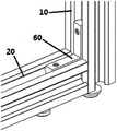
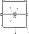
As shown in fig. 1, the frame of the conventional laser module includes a Y-direction guide rail and an X-direction connecting frame, and when the two are fixedly mounted and connected, a rotation stopping member is usually required to limit the rotation of the X-direction connecting frame, so that the mounting is troublesome and the cost is high.
Therefore, a new technical solution is needed to solve the above problems.
SUMMERY OF THE UTILITY MODEL
In order to solve the defects and shortcomings of the prior art, the utility model provides laser engraving equipment convenient to assemble, wherein the Y-direction guide rail is provided with the installation step for connecting the X-direction connecting frame, and the installation step limits the rotation of the X-direction connecting frame around the X axis; and the installation steps are arranged, so that the positioning of the X-direction connecting frame is facilitated.
In order to achieve the purpose, the utility model adopts the following technical scheme: a laser engraving device convenient to assemble comprises a rack and a laser module arranged on the rack, wherein the rack comprises a Y-direction guide rail and an X-direction connecting frame; wherein:
the Y-direction guide rail and the X-direction connecting frame are both square, the Y-direction guide rail is provided with a mounting step, and the X-direction connecting frame is connected to the mounting step; and the mounting step is provided with a stopping part for limiting the rotation of the X-direction connecting frame around the X-axis direction.
Preferably, the mounting step has a connecting wall surface and a stopper wall surface, the stopper wall surface forming the stopper portion, wherein: the connecting wall surface and the stop wall surface are vertical wall surfaces.
Preferably, the inner sides of the front end and the rear end of the Y-direction guide rail are provided with mounting steps.
As a preferable scheme, the Y-guide rail is provided with a first connection hole extending along the X direction at the installation step, the X-direction connector is provided with a second connection hole corresponding to the first connection hole, and during installation, the first connection hole and the second connection hole are sequentially penetrated by a connection screw, so that: the X-direction connecting frame is fixedly connected with the Y-direction guide rail.
Preferably, the Y-guide is a profile, and the upper side surface of the Y-guide has a guide groove for cooperating with the guide wheel.
Preferably, a graduated scale is arranged on the upper side face of the Y-direction guide rail.
Preferably, a strip-shaped mounting groove arranged along the Y direction is formed in the right side surface of the Y-direction guide rail.
As a preferable scheme, the laser module further comprises an X-direction guide rail which is slidably arranged on the Y-direction guide rail, and the laser module is arranged on the X-direction guide rail; wherein: x is provided with the sliding block to on the guide rail, the laser module install in the sliding block, just the downside of sliding block is provided with the X of drive sliding block motion to the motor.
Preferably, the X-direction guide rail, the Y-direction guide rail and the X-direction connecting frame are all made of aluminum materials.
Compared with the prior art, the Y-direction guide rail connecting device has the advantages and beneficial effects that particularly, the installation steps are arranged on the Y-direction guide rail and used for connecting the X-direction connecting frame, and limit the rotation of the X-direction connecting frame around an X axis by the installation steps, so that compared with the existing connecting mode, a stop part is omitted, and the installation is simpler and more convenient; the installation steps are arranged, so that the positioning of the X-direction connecting frame is facilitated;
in addition, the laser engraving equipment has simple and ingenious integral design and low weight, and is convenient for consumers to move.
To more clearly illustrate the structural features and effects of the present invention, the present invention will be described in detail below with reference to the accompanying drawings and specific embodiments.
Drawings
FIG. 1 is a perspective view of the prior art;
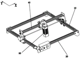
FIG. 2 is a perspective view of an embodiment of the present invention;
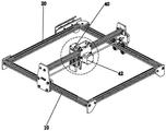
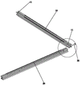
FIG. 3 is a perspective view of another embodiment of the present invention;
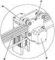
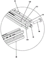
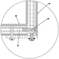
FIG. 4 is an enlarged partial schematic view of FIG. 3;
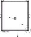
FIG. 5 is a top view of an embodiment of the present invention;
FIG. 6 is an exploded view of an embodiment of the present invention;
FIG. 7 is a partial schematic view of FIG. 6;
FIG. 8 is an enlarged partial schematic view of FIG. 7;
FIG. 9 is a schematic cross-sectional view of an embodiment of the present invention;
fig. 10 is a partially enlarged schematic view of fig. 9.
The attached drawings indicate the following:
10. a Y-direction guide rail; 11. mounting a step; 111. connecting the wall surfaces; 112. a stopper wall surface; 113. a first connection hole; 12. a guide groove; 13. a strip-shaped mounting groove; 20. an X-direction connecting frame; 21. a second connection hole; 30. a connecting screw; 40. an X-direction guide rail; 41. a slider; 42. an X-direction motor; 50. a laser module; 60. a rotation stopping member.
Detailed Description
The technical solutions in the embodiments of the present invention will be described clearly and completely with reference to the accompanying drawings, and it is obvious that the described embodiments are only preferred embodiments of the present invention.
Referring to fig. 1 to 10, the laser engraving apparatus convenient to assemble in the embodiment of the present invention includes a frame and a laser module 50 disposed on the frame, wherein the frame includes a Y-direction guide rail 10 and an X-direction connecting frame 20; wherein:
the Y-direction guide rail 10 and the X-direction connecting frame 20 are both square, the Y-direction guide rail 10 is provided with a mounting step 11, and the X-direction connecting frame 20 is connected to the mounting step 11; the mounting step 11 has a stopper portion for restricting the rotation of the X-direction connecting frame 20 in the X-axis direction.
In this way, the mounting step 11 is provided on the Y-guide rail 10 for connecting the X-connection frame 20, and the mounting step 11 limits the rotation of the X-connection frame 20 around the X-axis, thereby eliminating a stopper compared to the conventional connection method; and, the installation step 11 is arranged, so that the positioning of the X-direction connecting frame 20 is facilitated.
Preferably, the mounting step 11 has a connecting wall 111 and a stopper wall 112, the stopper wall 112 forming the stopper, wherein: the connecting wall 111 and the stopper wall 112 are vertical walls. Accordingly, the connecting end surface (right end surface) and the inner side surface of the X-direction connecting frame 20 are also vertical wall surfaces.
Further, mounting steps 11 are provided on the inner sides of the front and rear ends of the Y-guide rail 10. And, the X-direction connecting frame 20 is correspondingly connected; as shown in the drawings, the frame is shaped like a square, and has two X-direction connecting frames 20 and two Y-direction rails 10 parallel to each other.
Further, the Y-guide 10 is provided with a first connection hole 113 extending along the X direction at the installation step 11, the X-direction connection frame 20 is provided with a second connection hole 21 corresponding to the first connection hole 113, and during installation, a connection screw 30 sequentially penetrates the first connection hole 113 and the second connection hole 21, so that: the X-direction connecting frame 20 is fixedly connected to the Y-direction rail 10. Thus, the installation is simple and convenient; as shown in fig. 5, the laser engraving device of the present embodiment can adopt a modular split charging manner during transportation and sale, thereby saving transportation cost; in addition, the design of the installation and connection mode also facilitates the installation of subsequent users.
Further, the Y-guide 10 is a profile having a guide groove 12 on its upper side for cooperating with a guide wheel. Moreover, a graduated scale is arranged on the upper side surface of the Y-direction guide rail 10; a bar-shaped mounting groove 13 arranged along the Y direction is arranged on the right side surface of the Y-direction guide rail 10, and the first connecting hole 113 is arranged in the bar-shaped mounting groove 13; when in connection, the nut of the connecting screw 30 is positioned in the strip-shaped mounting groove 13, so that the advantages of safety and beauty are achieved; meanwhile, the drilling tool has the advantage of convenience in drilling.
Furthermore, the device also comprises an X-direction guide rail 40 which can be slidably arranged on the Y-direction guide rail 10, and the laser module 50 is arranged on the X-direction guide rail 40; wherein: a sliding block 41 is arranged on the X-direction guide rail 40, the laser module 50 is mounted on the sliding block 41, and an X-direction motor 42 for driving the sliding block 41 to move is arranged on the lower side of the sliding block 41; the X-direction motor 42 drives the laser module 50 to reciprocate along the X-direction guide rail 40;
meanwhile, the X-direction connecting frame 20 and the X-direction guide rail 40 are also section bars; the X-direction guide rail 40, the Y-direction guide rail 10 and the X-direction connecting frame 20 are all made of aluminum alloy materials; has the advantages of light structure and easy movement.
The X-direction connecting frame is mainly characterized in that the Y-direction guide rail is provided with the mounting step for connecting the X-direction connecting frame, and the mounting step limits the rotation of the X-direction connecting frame around the X axis; the installation steps are arranged, so that the positioning of the X-direction connecting frame is facilitated;
in addition, the laser engraving equipment has simple and ingenious integral design and low weight, and is convenient for consumers to move.
The above description is only a preferred embodiment of the present invention, and is not intended to limit the technical scope of the present invention, so that any minor modifications, equivalent changes and modifications made to the above embodiment according to the technical spirit of the present invention are within the technical scope of the present invention.
Claims (9)
1. The utility model provides a convenient laser engraving device of equipment which characterized in that: the laser module comprises a rack and a laser module arranged on the rack, wherein the rack comprises a Y-direction guide rail and an X-direction connecting frame; wherein:
the Y-direction guide rail and the X-direction connecting frame are both square, the Y-direction guide rail is provided with a mounting step, and the X-direction connecting frame is connected to the mounting step; and the mounting step is provided with a stopping part for limiting the rotation of the X-direction connecting frame around the X-axis direction.
2. The laser engraving apparatus convenient to assemble according to claim 1, wherein: the mounting step has a connecting wall surface and a stopper wall surface, the stopper wall surface forming the stopper portion, wherein: the connecting wall surface and the stop wall surface are vertical wall surfaces.
3. The laser engraving apparatus convenient to assemble according to claim 2, wherein: and mounting steps are arranged on the inner sides of the front end and the rear end of the Y-direction guide rail.
4. The laser engraving apparatus convenient to assemble according to claim 1, wherein: y to guide rail in installation step department is provided with along X to the first connecting hole that extends, X is provided with the second connecting hole that corresponds with first connecting hole to the link, during the installation, penetrates first connecting hole, second connecting hole in proper order through a connecting screw to make: the X-direction connecting frame is fixedly connected with the Y-direction guide rail.
5. The laser engraving apparatus convenient to assemble according to claim 1, wherein: the Y-direction guide rail is a section bar, and the upper side surface of the Y-direction guide rail is provided with a guide groove used for being matched with the guide wheel.
6. An easily assembled laser engraving apparatus according to claim 5, wherein: and a graduated scale is arranged on the upper side surface of the Y-direction guide rail.
7. An easily assembled laser engraving apparatus according to claim 5, wherein: and a strip-shaped mounting groove arranged along the Y direction is formed in the right side surface of the Y-direction guide rail.
8. The laser engraving apparatus convenient to assemble according to claim 1, wherein: the laser module is arranged on the X-direction guide rail; wherein: x is provided with the sliding block to on the guide rail, the laser module install in the sliding block, just the downside of sliding block is provided with the X of drive sliding block motion to the motor.
9. An easily assembled laser engraving apparatus according to claim 8, wherein: the X-direction guide rail, the Y-direction guide rail and the X-direction connecting frame are all made of aluminum materials.
Priority Applications (1)
| Application Number | Priority Date | Filing Date | Title |
|---|---|---|---|
| CN202220035276.3U CN216706354U (en) | 2022-01-08 | 2022-01-08 | Laser engraving equipment convenient to assemble |
Applications Claiming Priority (1)
| Application Number | Priority Date | Filing Date | Title |
|---|---|---|---|
| CN202220035276.3U CN216706354U (en) | 2022-01-08 | 2022-01-08 | Laser engraving equipment convenient to assemble |
Publications (1)
| Publication Number | Publication Date |
|---|---|
| CN216706354U true CN216706354U (en) | 2022-06-10 |
Family
ID=81890520
Family Applications (1)
| Application Number | Title | Priority Date | Filing Date |
|---|---|---|---|
| CN202220035276.3U Active CN216706354U (en) | 2022-01-08 | 2022-01-08 | Laser engraving equipment convenient to assemble |
Country Status (1)
| Country | Link |
|---|---|
| CN (1) | CN216706354U (en) |
-
2022
- 2022-01-08 CN CN202220035276.3U patent/CN216706354U/en active Active
Similar Documents
| Publication | Publication Date | Title |
|---|---|---|
| CN221725735U (en) | A preloading test device for a bridge cantilever construction hanging basket | |
| CN201988860U (en) | Light portal numerical control cutting machine | |
| CN221191187U (en) | T-shaped elevator guide rail | |
| CN217702484U (en) | External positioning device for nose of corner combining machine | |
| CN215701188U (en) | Miniaturized high-reliability double-lug end-toothed disc locking device | |
| CN214837851U (en) | Crossed roller sliding mechanism assembly | |
| CN211106397U (en) | Large-span inkjet printer | |
| CN220317001U (en) | Sightseeing aluminum alloy car coupling assembling | |
| CN209762194U (en) | Transmission locking device | |
| CN223089782U (en) | Aluminum profile installation structure | |
| CN221337486U (en) | Automatic assembling mechanism for aluminum alloy doors and windows | |
| CN218615461U (en) | Triaxial module device | |
| CN219331216U (en) | Assembled goods shelf | |
| CN216746518U (en) | Anti-clamping force detection device | |
| CN222971465U (en) | A screw tightening and clearance detection mechanism for steering wheel assembly | |
| CN220016735U (en) | Camera mounting structure is swept to line convenient to adjust | |
| CN222557356U (en) | Rack rail fixing assembly for rack rail | |
| CN220006691U (en) | Multi-guide-rail lens pressing machine | |
| CN223372006U (en) | Rail-changing station-entering structure for hanging system | |
| CN218787476U (en) | Connecting and fixing piece of photoelectric mounting column | |
| CN223867122U (en) | A convenient and recyclable guide beam structure | |
| CN213783054U (en) | Liquid feeding appearance displacement device | |
| CN222243109U (en) | A fully automatic, installation-free integrated laser engraving machine | |
| CN220228430U (en) | Measuring device for precision manufacturing | |
| CN221210624U (en) | Automatic movable button station suitable for large-span gantry machining center |
Legal Events
| Date | Code | Title | Description |
|---|---|---|---|
| GR01 | Patent grant | ||
| GR01 | Patent grant | ||
| PE01 | Entry into force of the registration of the contract for pledge of patent right | ||
| PE01 | Entry into force of the registration of the contract for pledge of patent right |
Denomination of utility model: A laser engraving equipment with convenient assembly Granted publication date: 20220610 Pledgee: Bank of China Co.,Ltd. Dongguan Branch Pledgor: DONGGUAN ANGTU INTELLIGENT TECHNOLOGY Co.,Ltd. Registration number: Y2024980007133 |