CN216705665U - Rapid stamping die for metal sheets - Google Patents
Rapid stamping die for metal sheets Download PDFInfo
- Publication number
- CN216705665U CN216705665U CN202122483512.6U CN202122483512U CN216705665U CN 216705665 U CN216705665 U CN 216705665U CN 202122483512 U CN202122483512 U CN 202122483512U CN 216705665 U CN216705665 U CN 216705665U
- Authority
- CN
- China
- Prior art keywords
- water tank
- fixedly connected
- die
- supporting
- supporting water
- Prior art date
- Legal status (The legal status is an assumption and is not a legal conclusion. Google has not performed a legal analysis and makes no representation as to the accuracy of the status listed.)
- Expired - Fee Related
Links
- 239000002184 metal Substances 0.000 title claims abstract description 14
- XLYOFNOQVPJJNP-UHFFFAOYSA-N water Substances O XLYOFNOQVPJJNP-UHFFFAOYSA-N 0.000 claims abstract description 41
- 239000011888 foil Substances 0.000 claims abstract description 15
- 239000004065 semiconductor Substances 0.000 claims abstract description 10
- 238000001816 cooling Methods 0.000 abstract description 7
- 238000000034 method Methods 0.000 abstract description 6
- 238000004080 punching Methods 0.000 abstract description 4
- 230000007423 decrease Effects 0.000 abstract description 3
- 238000001125 extrusion Methods 0.000 abstract description 3
- 238000005057 refrigeration Methods 0.000 abstract description 3
- 238000007493 shaping process Methods 0.000 abstract description 3
- 230000000694 effects Effects 0.000 description 2
- 230000004075 alteration Effects 0.000 description 1
- 230000009286 beneficial effect Effects 0.000 description 1
- 238000005516 engineering process Methods 0.000 description 1
- 238000012986 modification Methods 0.000 description 1
- 230000004048 modification Effects 0.000 description 1
- 238000003672 processing method Methods 0.000 description 1
- 238000000926 separation method Methods 0.000 description 1
- 238000006467 substitution reaction Methods 0.000 description 1
Images


Landscapes
- Punching Or Piercing (AREA)
Abstract
The utility model discloses a rapid stamping die for metal sheets, which comprises a supporting plate, wherein the upper surface of the supporting plate is fixedly connected with a supporting frame, the upper surface of the supporting frame is provided with a fixing hole, the inner wall of the fixing hole is provided with a hydraulic cylinder, the output end of the hydraulic cylinder is fixedly connected with a movable plate, the lower surface of the movable plate is provided with an upper die, and the left side and the right side of the upper die are both provided with limiting grooves. This quick stamping die of foil, the pneumatic cylinder passes through the fly leaf and drives the in-process that goes up mould decline and lower mould cooperation punching press, it descends to drive the filling block simultaneously, and get into inside the supporting water tank through the rectangular hole, because the semiconductor refrigerator can be with the inside water refrigeration of supporting water tank, the filling block is when removing to the interior diapire of supporting water tank, because two filling blocks extrusion water, make the water level in the supporting water tank rise, and pour into the rectangular channel through the through-hole in, carry out quick cooling with the foil in the lower mould, the cooling efficiency of foil after the shaping and lower mould has been improved.
Description
Technical Field
The utility model relates to the technical field of part stamping, in particular to a metal sheet rapid stamping die.
Background
The stamping is a forming processing method which applies external force to plates, strips, pipes, profiles and the like by a press and a die to cause plastic deformation or separation of the plates, the strips, the pipes, the profiles and the like so as to obtain workpieces with required shapes and sizes, and is one of main methods of metal plastic processing, wherein the plates, the die and stamping equipment are three essential elements in the processing process.
Current stamping die is when using, because the foil surface receives behind great pressure in stamping process, can produce deformation to the surface produces certain heat, however current stamping equipment is relatively poor to the cooling effect on foil surface, makes the foil intensity after the punching press not enough on the one hand, also can produce the heat altered shape in the on the other hand mould, and then has reduced mould life, and is comparatively inconvenient during the use.
SUMMERY OF THE UTILITY MODEL
The utility model aims to provide a metal sheet rapid stamping die to solve the problems in the background technology.
In order to achieve the purpose, the utility model provides the following technical scheme: the utility model provides a quick stamping die of foil, which comprises a supporting plate and i, the last fixed surface of backup pad is connected with the support frame, the fixed orifices has been seted up to the upper surface of support frame, the pneumatic cylinder is installed to the inner wall of fixed orifices, the output fixedly connected with fly leaf of pneumatic cylinder, the lower surface mounting of fly leaf has last mould, the spacing groove has all been seted up to the left and right sides of last mould, the last fixed surface of backup pad is connected with supporting water tank, the rectangular channel has been seted up to supporting water tank's upper surface, the lower mould is installed to the inner diapire of rectangular channel, and the through-hole has all been seted up to the inner wall about the rectangular channel, two filling blocks of lower fixed surface of fly leaf are connected with, two rectangular holes have been seted up to supporting water tank's upper surface, the semiconductor refrigerator is installed in supporting water tank's left side.
Preferably, the left side and the right side of the movable plate are respectively connected with the left inner wall and the right inner wall of the support frame in a sliding mode.
Preferably, the filling block is matched with the rectangular hole, and the refrigerating end of the semiconductor refrigerator extends to the inside of the supporting water tank.
Preferably, the lower surface of the movable plate is fixedly connected with two connecting plates, and the lower surfaces of the two connecting plates are fixedly connected with a positioning plate.
Preferably, the side surfaces of the two connecting plates are connected with ejector rods in a sliding mode, the ejector rods are matched with the inner walls of the limiting grooves, and the surfaces of the ejector rods are fixedly connected with ejector plates.
Preferably, two the equal fixedly connected with spring in the back of the body of roof, the one end that the roof was kept away from to the spring is fixedly connected with the side of connecting plate.
Advantageous effects
The utility model provides a metal sheet rapid stamping die which has the following beneficial effects:
1. this quick stamping die of foil, the pneumatic cylinder passes through the fly leaf and drives the in-process that goes up mould decline and lower mould cooperation punching press, it descends to drive the filling block simultaneously, and get into inside the supporting water tank through the rectangular hole, because the semiconductor refrigerator can be with the inside water refrigeration of supporting water tank, the filling block is when removing to the interior diapire of supporting water tank, because two filling blocks extrusion water, make the water level in the supporting water tank rise, and pour into the rectangular channel through the through-hole in, carry out quick cooling with the foil in the lower mould, the cooling efficiency of foil after the shaping and lower mould has been improved.
2. This quick stamping die of foil stimulates two ejector pins, makes the roof drive the spring and produces deformation, will go up the mould simultaneously and take out under the locating plate, and the dismantlement is changed to last mould to the convenience, has effectively solved traditional mould and has been difficult to change, and then influences the problem of stamping efficiency easily, when making things convenient for the dismouting, stability is also higher, and is more convenient during the use.
Drawings
FIG. 1 is a schematic front sectional view of the present invention;
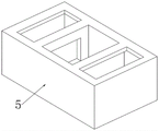
FIG. 2 is a schematic perspective view of a support tank according to the present invention;
fig. 3 is an enlarged schematic view of a structure in fig. 1.
In the figure: the device comprises a supporting plate 1, a supporting frame 2, a movable plate 3, an upper die 4, a supporting water tank 5, a lower die 6, a filling block 7, a semiconductor refrigerator 8, a connecting plate 9, a positioning plate 10, an ejector rod 11, a top plate 12 and a spring 13.
Detailed Description
The technical solutions in the embodiments of the present invention will be clearly and completely described below with reference to the drawings in the embodiments of the present invention, and it is obvious that the described embodiments are only a part of the embodiments of the present invention, and not all of the embodiments. All other embodiments, which can be derived by a person skilled in the art from the embodiments given herein without making any creative effort, shall fall within the protection scope of the present invention.
Referring to fig. 1-3, the present invention provides a technical solution: the utility model provides a quick stamping die of foil, includes backup pad 1, and the last fixed surface of backup pad 1 is connected with support frame 2, and the fixed orifices has been seted up to the upper surface of support frame 2, and the pneumatic cylinder is installed to the inner wall of fixed orifices, the output fixedly connected with fly leaf 3 of pneumatic cylinder, the left and right sides of fly leaf 3 respectively with support frame 2 control inner wall sliding connection.
The lower surface mounting of fly leaf 3 has last mould 4, and the spacing groove has all been seted up to the left and right sides of going up mould 4, and the last fixed surface of backup pad 1 is connected with supporting water tank 5, and the rectangular channel has been seted up to supporting water tank 5's upper surface, and lower mould 6 is installed to the inner bottom wall in rectangular channel, and the through-hole has all been seted up to the inner wall about the rectangular channel.
Two filling blocks 7 are fixedly connected to the lower surface of the movable plate 3, two rectangular holes are formed in the upper surface of the supporting water tank 5, the filling blocks 7 are matched with the rectangular holes, a semiconductor refrigerator 8 is installed on the left side of the supporting water tank 5, and a refrigerating end of the semiconductor refrigerator 8 extends to the inside of the supporting water tank 5.
The pneumatic cylinder passes through the in-process that fly leaf 3 drove last mould 4 decline and the punching press of 6 cooperation of lower mould, it descends to drive filling block 7 simultaneously, and get into through the rectangular hole and support 5 insidely, because semiconductor cooler 8 can be with the water refrigeration of 5 insides of supporting water tank, filling block 7 is when removing the diapire to 5 inside supporting water tank, because two filling block 7 extrusion water, make the water level in the supporting water tank 5 rise, and pour into the rectangular channel through the through-hole in, carry out quick cooling with the foil in the lower mould 6, the foil after the shaping and the cooling efficiency of lower mould 6 have been improved.
The lower surface of the movable plate 3 is fixedly connected with two connecting plates 9, the lower surfaces of the two connecting plates 9 are fixedly connected with a positioning plate 10, the side surfaces of the two connecting plates 9 are respectively connected with a mandril 11 in a sliding mode, and the mandril 11 is matched with the inner wall of the limiting groove.
The surface fixed connection of ejector pin 11 has roof 12, and the equal fixedly connected with spring 13 in the back of the body of two roof 12, the one end that roof 12 was kept away from to spring 13 and the side fixed connection of connecting plate 9.
Two ejector pins 11 of pulling make roof 12 drive spring 13 and produce deformation, will go up mould 4 simultaneously and take out from locating plate 10 down, conveniently change the dismantlement to last mould 4, effectively solved traditional mould and be difficult to change, and then influence the problem of stamping efficiency easily, when making things convenient for the dismouting, stability is also higher, and is more convenient during the use.
The working principle is as follows: when the rapid stamping die is used, firstly, a metal sheet is placed on a lower die 6, a hydraulic cylinder is opened, the hydraulic cylinder drives an upper die 4 to descend through a movable plate 3, the upper die 4 and the lower die 6 are matched to stamp the metal sheet, meanwhile, the movable plate 3 drives two filling blocks 7 to move to the inside of a supporting water tank 5, the water level in the supporting water tank 5 is raised, water in the supporting water tank 5 is poured into a rectangular groove, the lower die 6 and the formed metal sheet are rapidly cooled, the strength of the metal sheet and the service life of the lower die 6 are improved, when the upper die 4 is seriously worn and needs to be replaced, ejector rods 11 are pulled to two sides, the ejector rods 11 extrude springs 13 through ejector plates 12, the two ejector rods 11 are separated from limiting grooves in the side surface of the upper die 4, the upper die 4 is taken out from the lower part of a positioning plate 10, the replacement can be carried out, the disassembly and assembly efficiency is improved, and the stability is higher, the use is more convenient.
Although embodiments of the present invention have been shown and described, it will be appreciated by those skilled in the art that changes, modifications, substitutions and alterations can be made in these embodiments without departing from the principles and spirit of the utility model, the scope of which is defined in the appended claims and their equivalents.
Claims (6)
1. The utility model provides a quick stamping die of foil, includes backup pad (1), the last fixed surface of backup pad (1) is connected with support frame (2), its characterized in that: the fixed orifices has been seted up to the upper surface of support frame (2), the pneumatic cylinder is installed to the inner wall of fixed orifices, the output fixedly connected with fly leaf (3) of pneumatic cylinder, the lower surface mounting of fly leaf (3) has last mould (4), the spacing groove has all been seted up to the left and right sides of going up mould (4), the last fixed surface of backup pad (1) is connected with supporting water tank (5), the rectangular channel has been seted up to the upper surface of supporting water tank (5), lower mould (6) are installed to the inner bottom wall of rectangular channel, and the through-hole has all been seted up to the inner wall about the rectangular channel, two filling blocks (7) of lower fixed surface fixedly connected with of fly leaf (3), two rectangular holes have been seted up to the upper surface of supporting water tank (5), semiconductor cooler (8) are installed in the left side of supporting water tank (5).
2. The die for rapidly stamping a metal sheet as claimed in claim 1, wherein: the left side and the right side of the movable plate (3) are respectively connected with the left inner wall and the right inner wall of the support frame (2) in a sliding manner.
3. The die for rapidly stamping a metal sheet as claimed in claim 1, wherein: the filling block (7) is matched with the rectangular hole, and the refrigerating end of the semiconductor refrigerator (8) extends to the inside of the supporting water tank (5).
4. The die for rapidly stamping a metal sheet as claimed in claim 1, wherein: the lower surface of the movable plate (3) is fixedly connected with two connecting plates (9), and the lower surfaces of the two connecting plates (9) are fixedly connected with a positioning plate (10).
5. The die set of claim 4, wherein: the side surfaces of the two connecting plates (9) are all connected with ejector rods (11) in a sliding mode, the ejector rods (11) are matched with the inner wall of the limiting groove, and the surface of each ejector rod (11) is fixedly connected with a top plate (12).
6. The die set of claim 5, wherein: two equal fixedly connected with spring (13) in the back of body of roof (12), the one end that roof (12) were kept away from in spring (13) and the side fixed connection of connecting plate (9).
Priority Applications (1)
| Application Number | Priority Date | Filing Date | Title |
|---|---|---|---|
| CN202122483512.6U CN216705665U (en) | 2021-10-15 | 2021-10-15 | Rapid stamping die for metal sheets |
Applications Claiming Priority (1)
| Application Number | Priority Date | Filing Date | Title |
|---|---|---|---|
| CN202122483512.6U CN216705665U (en) | 2021-10-15 | 2021-10-15 | Rapid stamping die for metal sheets |
Publications (1)
| Publication Number | Publication Date |
|---|---|
| CN216705665U true CN216705665U (en) | 2022-06-10 |
Family
ID=81876700
Family Applications (1)
| Application Number | Title | Priority Date | Filing Date |
|---|---|---|---|
| CN202122483512.6U Expired - Fee Related CN216705665U (en) | 2021-10-15 | 2021-10-15 | Rapid stamping die for metal sheets |
Country Status (1)
| Country | Link |
|---|---|
| CN (1) | CN216705665U (en) |
Cited By (2)
| Publication number | Priority date | Publication date | Assignee | Title |
|---|---|---|---|---|
| CN116198037A (en) * | 2022-12-20 | 2023-06-02 | 西安顺晖电子科技有限公司 | Semiconductor device slicing device |
| CN119634532A (en) * | 2025-02-17 | 2025-03-18 | 吉林省北尔特机电科技有限公司 | A copper water stop joint integrated stamping forming device and process |
-
2021
- 2021-10-15 CN CN202122483512.6U patent/CN216705665U/en not_active Expired - Fee Related
Cited By (2)
| Publication number | Priority date | Publication date | Assignee | Title |
|---|---|---|---|---|
| CN116198037A (en) * | 2022-12-20 | 2023-06-02 | 西安顺晖电子科技有限公司 | Semiconductor device slicing device |
| CN119634532A (en) * | 2025-02-17 | 2025-03-18 | 吉林省北尔特机电科技有限公司 | A copper water stop joint integrated stamping forming device and process |
Similar Documents
| Publication | Publication Date | Title |
|---|---|---|
| CN213002183U (en) | A metal structural part stamping die | |
| CN211071475U (en) | Digit control machine tool mould punching press mechanism | |
| CN219052603U (en) | Stamping forming die | |
| CN109226514B (en) | Mobile phone shell stamping die | |
| CN218134449U (en) | Punch forming die for metal materials | |
| CN220970551U (en) | Stamping mechanical die convenient for replacing and installing die head | |
| CN210632674U (en) | Quick aluminium alloy extrusion device | |
| CN116213560A (en) | A stamping device capable of quickly changing molds | |
| CN112642939B (en) | Stamping die capable of being rapidly positioned based on upper die and lower die | |
| CN218798602U (en) | Stamping jig of battery cover | |
| CN213288399U (en) | Be used for integrative aluminium apron plastic stamping die of new forms of energy battery | |
| CN215614442U (en) | Stamping die for hardware orifice plate | |
| CN218192128U (en) | Novel bulging processing die for deep-drawing parts | |
| CN217595647U (en) | Stamping plate stamping device convenient to change mould | |
| CN214161022U (en) | Stamping die shaping stop device | |
| CN213613678U (en) | A stamping die that is easy to discharge | |
| CN215587618U (en) | Stamping part die | |
| CN108714674A (en) | A kind of metal product casting diel | |
| CN212042326U (en) | Punch forming die for manufacturing refrigerator air duct cover plate | |
| CN210936740U (en) | Novel machine tool die for producing broken steel plate nails | |
| CN217252338U (en) | Stamping die is used in processing of metal furniture accessory | |
| CN219004239U (en) | Nitrogen spring cylinder type part deep drawing die | |
| CN208083087U (en) | A kind of preforming extrusion die of aluminum enclosure | |
| CN217223206U (en) | Cold storage plate punch forming device | |
| CN211279375U (en) | Fuse melt processing mold |
Legal Events
| Date | Code | Title | Description |
|---|---|---|---|
| GR01 | Patent grant | ||
| GR01 | Patent grant | ||
| CF01 | Termination of patent right due to non-payment of annual fee | ||
| CF01 | Termination of patent right due to non-payment of annual fee |
Granted publication date: 20220610 |