SUMMERY OF THE UTILITY MODEL
The main aim at of this application provides a V type mixes machine can overcome the unable problem of smashing of part large granule material when mixing the quick-witted pay-off, guarantees material mixing quality.
In order to achieve the purpose, the application provides a V-shaped mixing machine which comprises a supporting frame, a mixing component and a feeding component;
the mixing assembly comprises a V-shaped barrel, a first motor and a stirrer, the V-shaped barrel is mounted on the support frame through a rotating part, the first motor is mounted at the top of the V-shaped barrel through a motor base, the stirrer is mounted in the V-shaped barrel, the upper end of the stirrer penetrates through the top of the V-shaped barrel, one end of the stirrer is connected with a rotating shaft of the first motor through a coupler, and a discharge nozzle is arranged at the bottom of the V-shaped barrel; the feeding subassembly includes inlet pipe, feeding mouth, filters piece and guide, the one end of inlet pipe with the lateral wall intercommunication of V type barrel, the other end with the ejection of compact of feeding mouth is mutually linked, it installs through the guide to filter the piece in the feeding mouth, install a vibrating motor through the bolt on the lateral wall of feeding mouth.
Preferably, in the above V-shaped mixer, the filter member includes a filter screen and a frame, the filter screen is welded and fixed in the frame, and the filter screen is a stainless steel filter screen.
More preferably, in the above V-shaped mixer, the guide member includes a guide block and a guide groove, the guide block is slidably mounted in the guide groove, one side of the guide block is fixedly connected to the outer wall of the frame, and the guide groove is opened on the inner wall of the feeding nozzle.
Further preferably, in the V-shaped mixer, an inner wall of the guide groove is in clearance sliding fit with a side wall of the guide block.
Further preferably, in the V-shaped mixer, the support frame includes a base, and two support plates are fixed to the base.
Further preferably, in the above-mentioned V type mixes machine, it includes dwang, bearing, first gear, second gear and second motor to rotate the piece, the one end of dwang with the lateral wall fixed connection of V type barrel, the other end of dwang is fixed to be pegged graft in the inner circle of bearing, the bearing is installed in the lateral wall of backup pad, the one end of dwang runs through in one the lateral wall of backup pad, just the tip of dwang with first gear key-type connection, key connection has the second gear in the axis of rotation of second motor, the second gear with first gear meshes mutually.
Further preferably, in the above-mentioned V-shaped mixer, a third motor is installed through the motor cabinet in the V-shaped inslot of the V-shaped barrel, the axis of rotation of third motor has spiral conveying head through the coupling joint, spiral conveying head is located in the V-shaped barrel, just one end of spiral conveying head is located in the ejection of compact mouth.
Further preferably, in the V-shaped mixer, a discharge valve is mounted at the discharge nozzle, and a second vibration motor is mounted on a side wall of the bottom of the V-shaped cylinder.
Compared with the prior art, the technical scheme of the application is simple in structure and easy to realize. When the materials in the V-shaped cylinder are mixed, the second motor is turned on to drive the second gear to rotate, so that the first gear is driven to rotate, and the rotating rod rotates by taking the inner ring of the bearing as an axis, therefore, the V-shaped cylinder swings, and when the stirrer stirs, the V-shaped cylinder swings, so that the materials collide with the stirrer, and the mixing efficiency is effectively improved.
Detailed Description
In order to make the technical solutions better understood by those skilled in the art, the technical solutions in the embodiments of the present application will be described below with reference to the drawings in the embodiments of the present application.
It should be noted that the terms "first" and "second" in the description and claims of the present application and the drawings described above are used for distinguishing similar objects and not for describing a particular sequential or chronological order. The terms "upper," "lower," "left," "right," "front," "back," "top," "bottom," "inner," "outer," "center," "vertical," "horizontal," "lateral," "longitudinal," and the like are used in an orientation or positional relationship to one another based on the orientation or positional relationship shown in the drawings and are not intended to define or be constructed and operated in a particular orientation or orientation of the indicated device, element, or component.
As shown in fig. 1-3, example 1:
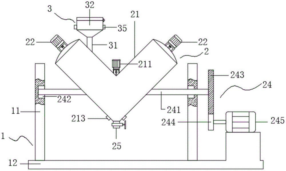
the utility model provides a V type mixes machine, includes support frame 1, compounding subassembly 2 and feeding subassembly 3, and compounding subassembly 2 is installed at support frame 1, and feeding subassembly 3 is installed on the upper portion of compounding subassembly 2, and support frame 1 is used for supporting wholly, and compounding subassembly 2 is used for mixing the material, and feeding subassembly 3 is arranged in intercepting the large granule material of adulteration in the material.
Wherein, support frame 1 includes two backup pads 11 and base 12, and two backup pads 11 welded fastening are on base 12, and backup pad 11 is used for supporting the V type barrel, and base 12 is used for supporting whole, adopts the bolt to install subaerial.
The mixing component 2 comprises a V-shaped cylinder 21, a first motor 22 and stirrers 23, the stirrers 23 are arranged to be push-type stirrers, the number of the first motors 22 is two, the two first motors 22 are respectively arranged at two branch end parts of the upper end of the V-shaped cylinder 21, the number of the stirrers 23 is the same as that of the first motors 22, the V-shaped cylinder 21 is arranged in the support frame 1 through a rotating part 24, the first motor 22 is arranged at the top of the V-shaped cylinder 21 through a motor base, the stirrers 23 are arranged in the V-shaped cylinder 21, the upper end of each stirrer 23 penetrates through the top of the V-shaped cylinder 21, one end of the stirrer 23 is connected with a rotating shaft of the first motor 22 through a coupling, the bottom of the V-shaped cylinder 21 is provided with a discharging nozzle 25, and through the use of the mixing component 2, when the mixer is used, the first motor 22 rotates to drive the stirrer 23 to rotate, so that the materials in the V-shaped cylinder 21 are stirred and mixed.
The feeding assembly 3 comprises a feeding pipe 31, a feeding nozzle 32, a filtering piece 33 and a guiding piece 34, the filtering piece 33 comprises a filtering net 331 and a frame 332, a handle is installed on the frame 332 and used for installing and replacing the frame 332, the filtering net 331 is welded and fixed in the frame 332, a stainless steel filtering net is arranged on the filtering net 331, the guiding piece 34 comprises a guiding block 341 and a guiding groove 342, the guiding block 341 is slidably installed in the guiding groove 342, one side of the guiding block 341 is fixedly connected with the outer wall of the frame 332, the guiding groove 342 is arranged on the inner wall of the feeding nozzle 32, the inner wall of the guiding groove 342 is in clearance sliding fit with the side wall of the guiding block 341, the clearance is not more than 1mm, through the matching use of the guiding block 341 and the guiding groove 342, the replacement and installation of the filtering net 331 are convenient for workers, the workers can clean the filtering net 331 and the operation of the workers are convenient, one end of the feeding pipe 31 is communicated with the side wall of the V-shaped barrel body 21, the other end of the feeding pipe 31 is communicated with the discharging part of the feeding nozzle 32, the filter element 33 is arranged in the feeding nozzle 32 through the guide element 34, the feeding nozzle 32 is hinged with a dustproof cover, the side wall of the feeding nozzle 32 is provided with a first vibration motor 35 through a bolt, through the use of the feeding assembly 3, when feeding materials into the V-shaped cylinder 21, a worker opens the dustproof cover on the feeding nozzle 32, then pours the materials onto the filter screen 331, then opens the first vibration motor 35 to vibrate the filter screen 331, so as to accelerate the materials on the filter screen 331 to fall into the V-shaped cylinder 21, then large granular materials doped in the materials are intercepted by the filter screen 331, the worker takes out the large granular materials, after the feeding operation is completed, the worker closes the dustproof cover, when feeding materials with different grain sizes, the frame 332 is arranged in the feeding nozzle 32 in a sliding mode through the matching of the guide groove 342 and the guide block 341, the frame 332 is taken out of the feed nozzle 32 so that the screen 331 is replaced and the cleaning of the screen 331 by a worker is facilitated.
The rotating member 24 includes a rotating rod 241, a bearing 242, a first gear 243, a second gear 244 and a second motor 245, the second motor 245 is a servo motor, the rotation range of the V-shaped cylinder 21 is set to ± 3 °, one end of the rotating rod 241 is fixedly connected with a side wall of the V-shaped cylinder 21, the other end of the rotating rod 241 is fixedly inserted into an inner ring of the bearing 242, the bearing 242 is installed on a side wall of one of the support plates 11, one end of the rotating rod 241 penetrates through a side wall of one of the support plates 11, an end of the rotating rod 241 is connected with the first gear 243 in a key manner, the second gear 244 is connected to a rotating shaft of the second motor 245 in a key manner, the second gear 244 is engaged with the first gear 243, and by using the rotating member 24, when materials in the V-shaped cylinder 21 are mixed, the second gear 244 is driven to rotate by opening the second motor 245, the first gear 243 is driven to rotate, and the rotating rod 241 rotates around an inner ring of the bearing 242, therefore, the V-shaped cylinder 21 swings, and when the stirrer 23 stirs, the V-shaped cylinder swings, so that the materials collide with the stirrer, and the mixing efficiency is effectively improved.
In this embodiment, a third motor 211 is installed in a V-shaped groove of the V-shaped cylinder 21 through a motor base, a rotation shaft of the third motor 211 is connected to a screw delivery head 212 through a coupling, the screw delivery head 212 is located in the V-shaped cylinder 21, one end of the screw delivery head 212 is located in the discharge nozzle 25, a discharge valve is installed at the discharge nozzle 25, a second vibration motor 213 is installed on a bottom side wall of the V-shaped cylinder 21 through a bolt, when the material in the V-shaped cylinder 21 is stirred, the third motor 211 is turned on to drive the screw delivery head 212 to rotate, and the material is stirred, when the material is discharged, the third motor 211 is turned on to drive the screw delivery head 212 to rotate, and is matched with the second vibration motor 213, so that the discharge of the material mixed in the V-shaped cylinder 21 is accelerated, and the situation that the discharge nozzle 25 is blocked by the material is reduced.
In practice, the working process is as follows:
the V-shaped cylinder 21 is first fed and the worker opens the dust cap on the feed nozzle 32 and pours the material onto the screen 331. Meanwhile, the first vibration motor 35 is started to vibrate the filter screen 331, so that the material on the filter screen 331 falls into the V-shaped cylinder 21 at an accelerated speed, then the large-particle material doped in the material is intercepted by the filter screen 331, a worker takes out the large-particle material, and after the feeding operation is completed, the worker closes the dust cover. When materials with different particle sizes are fed, the frame 332 is slidably mounted in the feeding nozzle 32 through the matching of the guide groove 342 and the guide block 341, the frame 332 is taken out of the feeding nozzle 32, so as to replace the filter screen 331, the filter screen 331 is convenient to clean, the stirrer 23 is driven to rotate through the rotation of the first motor 22, so as to stir and mix the materials in the V-shaped cylinder 21, the first gear 243 is driven to rotate when the second motor 245 is opened to drive the second gear 244 to rotate, so as to drive the rotating rod 241 to rotate by taking the inner ring of the bearing 242 as an axis, so as to swing the V-shaped cylinder 21, when the stirrer 23 stirs, the V-shaped cylinder is swung, so that the materials collide with the stirrer, the mixing efficiency is effectively improved, when the materials in the V-shaped cylinder 21 are stirred, the third motor 211 is opened to drive the spiral material conveying head 212 to rotate, stir the material, when the ejection of compact, open third motor 211, drive spiral delivery head 212 and rotate, with the cooperation of second vibrating motor 213 for the material discharge after the mixture in the V type barrel 21, the condition of ejection of compact 25 is plugged up to effectual reduction material.
The above description is only for the purpose of illustrating the preferred embodiments of the present application and is not to be construed as limiting the present application, and it will be apparent to those skilled in the art that modifications, equivalents and the like can be made within the spirit and scope of the present application.