CN216682351U - Paper angle bead cutting device - Google Patents
Paper angle bead cutting device Download PDFInfo
- Publication number
- CN216682351U CN216682351U CN202123320517.3U CN202123320517U CN216682351U CN 216682351 U CN216682351 U CN 216682351U CN 202123320517 U CN202123320517 U CN 202123320517U CN 216682351 U CN216682351 U CN 216682351U
- Authority
- CN
- China
- Prior art keywords
- mounting
- fixedly connected
- cutting device
- pull rod
- plate
- Prior art date
- Legal status (The legal status is an assumption and is not a legal conclusion. Google has not performed a legal analysis and makes no representation as to the accuracy of the status listed.)
- Expired - Fee Related
Links
- 239000011324 bead Substances 0.000 title claims abstract description 26
- 230000001012 protector Effects 0.000 claims description 13
- 230000008602 contraction Effects 0.000 claims description 8
- 210000001503 joint Anatomy 0.000 claims description 8
- 238000009434 installation Methods 0.000 abstract description 16
- 238000012545 processing Methods 0.000 abstract description 10
- 238000000034 method Methods 0.000 abstract description 5
- 238000012856 packing Methods 0.000 abstract description 3
- 239000000123 paper Substances 0.000 description 23
- 230000000694 effects Effects 0.000 description 4
- 239000000463 material Substances 0.000 description 2
- 230000000149 penetrating effect Effects 0.000 description 2
- 238000005299 abrasion Methods 0.000 description 1
- 238000013461 design Methods 0.000 description 1
- 238000001125 extrusion Methods 0.000 description 1
- 239000002655 kraft paper Substances 0.000 description 1
- 238000004806 packaging method and process Methods 0.000 description 1
- 238000012552 review Methods 0.000 description 1
Images



Landscapes
- Nonmetal Cutting Devices (AREA)
Abstract
The application discloses paper angle bead cutting device relates to packing processing technology field, including mounting plate, mounting plate's upside surface is provided with the work piece supporting shoe, mounting plate's upside fixed surface is connected with n type support, two installation pieces of the downside surface difference fixedly connected with of work piece supporting shoe, two one side that the installation piece is relative sets up to the inclined plane, two mounting grooves have been seted up respectively to mounting plate's upside surface, the downside of installation piece extends into in the mounting groove, set up the control chamber that is located between two mounting grooves in the mounting plate, sliding connection has two dead levers respectively in the control chamber. This paper angle bead cutting device is convenient for install the work piece supporting shoe of different shapes, and the device is applicable to the processing of the paper angle bead of different shapes, has further improved the device's practicality and use value, has further improved the efficiency of tailorring to different shapes paper angle beads, has improved the process velocity of processing paper angle bead.
Description
Technical Field
The application relates to the technical field of packaging and processing, in particular to a paper corner protector cutting device.
Background
The paper angle bead is the parcel that is used for the product outward appearance, in order to do benefit to the protection of transportation or handling process to the product outward appearance, the paper angle bead is after many kraft papers are replyed, it forms to finalize the design and suppress through the angle bead machine, be used for behind the goods pile, can strengthen packing material edge holding power and protect its whole packing intensity, when the product tray is gathered, according to the product pile height, need use the paper angle bead of different length, make the corner of product obtain the protection, avoid appearing the striking and the damage in appearance, consequently, need cut the paper angle bead according to a take the dimensions.
The review of the literature discloses a paper corner protector cutting device which adopts a mechanical cutting mode to improve the cutting efficiency and reduce the abrasion of the paper corner protector in the feeding process.
However, the scheme has the following disadvantages in the using process: the workpiece supporting block in the scheme is only suitable for processing the paper angle bead with one shape, however, the existing paper angle bead contains various shapes such as L shape, U shape, special shape and the like, so that the scheme cannot be suitable for processing the paper angle bead with different shapes, the practicability and the practical value of the scheme are seriously reduced, and the processing efficiency during cutting the paper angle bead is also influenced.
SUMMERY OF THE UTILITY MODEL
In order to realize the purpose that is applicable to the processing of the paper angle bead of different shapes, this application provides following technical scheme: a paper corner protector cutting device comprises an installation bottom plate, wherein a workpiece supporting block is arranged on the upper side surface of the installation bottom plate, and an n-shaped support is fixedly connected to the upper side surface of the installation bottom plate;
the utility model discloses a workpiece support piece, including work piece supporting shoe, mounting plate, fixing hole, dead lever and mounting plate inner wall sliding connection, two installation pieces of downside surface difference fixedly connected with of work piece supporting shoe, two one side that the installation piece is relative sets up to the inclined plane, two mounting grooves have been seted up respectively to mounting plate's upside surface, the downside of installation piece extends into the mounting groove in, two the fixed orifices has all been seted up on the surface to one side that the installation piece is relative, set up the control chamber that is located between two mounting grooves in the mounting plate, sliding connection has two dead levers respectively in the control chamber, but the dead lever card goes into corresponding fixed orifices, two the one end that the dead lever is opposite runs through respectively into in two mounting grooves and with mounting plate inner wall sliding connection.
Preferably, the dead lever is located one of control intracavity and serves fixedly connected with connecting plate, one side fixed surface of connecting plate towards the dead lever is connected with the activity and cup joints the extension spring on the dead lever, one side fixed connection that the extension spring is kept away from the connecting plate is on the control chamber towards one side inner wall of connecting plate.
Preferably, the control cavity is internally and slidably connected with a first pull rod, the other end of the first pull rod penetrates through the outer surface of the mounting base plate, and the first pull rod is slidably connected with the inner wall of the mounting base plate.
Preferably, one side surface of the connecting plate facing the first pull rod is rotatably connected with a control pull plate, and the control pull plate is far away from the connecting plate and is rotatably connected to the outer surface of the first pull rod.
Preferably, the upper side fixed surface of n type support is connected with cuts the actuating cylinder, the output that cuts the actuating cylinder runs through the lower surface of the diaphragm of n type support, fixedly connected with mounting panel on the output that cuts the actuating cylinder, the downside surface of mounting panel is provided with cuts out the sword.
Preferably, the butt joint groove has been seted up on the downside surface of mounting panel, the upside of tailorring the sword extends into the butt joint inslot, the joint hole has been seted up to the side of tailorring the sword, the shrink chamber has been seted up in the mounting panel, the joint piece that advances in the butt joint inslot is run through to shrink intracavity sliding connection one side, joint piece and mounting panel inner wall sliding connection, the sword of tailorring is seted up the joint hole identical with the joint piece on the surface to one side of joint piece.
Preferably, a second pull rod is fixedly connected to the surface of one side, located in the shrinkage cavity, of the clamping block, and one end, far away from the clamping block, of the second pull rod penetrates through the outer surface of the mounting plate and is in sliding connection with the inner wall of the mounting plate.
Preferably, a supporting spring movably sleeved on the second pull rod is fixedly connected to the surface of one side, facing the second pull rod, of the clamping block, and one side, far away from the clamping block, of the supporting spring is fixedly connected to the inner wall of the contraction cavity.
In view of the above, it is desirable to provide,
1. this paper angle bead cutting device is convenient for install the work piece supporting shoe of different shapes to make the device be applicable to the processing of the paper angle bead of different shapes, further improved the device's practicality and use value, further improved the efficiency of tailorring to different shapes paper angle beads, improved the process velocity of processing paper angle bead.
2. This paper angle bead cutting device is convenient for will tailor the sword and change, has further ensured the effect of tailorring to paper angle bead, has improved the material efficiency to paper angle bead, tailors the sword simultaneously and changes convenient operation, and is simple to use, has further reduced staff's working strength, has ensured the efficiency when tailorring the sword and changing.
Drawings
FIG. 1 is a schematic view of a paper corner protector cutting device according to the present application;
FIG. 2 is a schematic view of the present application illustrating removal of the support block;
FIG. 3 is a top plan view of the mounting plate of the present application;
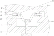
FIG. 4 is a schematic view of the present application showing the mounting plate and the cutting blade removed;
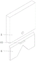
FIG. 5 is a side plan view of the mounting plate of the present application.
Description of reference numerals:
the cutting machine comprises a mounting base plate 1, a workpiece supporting block 2, a mounting block 21, a mounting groove 22, a fixing hole 23, a control cavity 24, a fixing rod 25, a connecting plate 26, a tension spring 27, a first pull rod 28, a control pull plate 29, a 3 n-shaped support, a cutting driving cylinder 4, a mounting plate 5, a cutting knife 6, a clamping hole 61, a butt joint groove 62, a contraction cavity 63, a clamping block 64, a second pull rod 65 and a supporting spring 66.
Detailed Description
Referring to fig. 1-3, the present application provides a new technical solution: the utility model provides a paper angle bead cutting device, including mounting plate 1, mounting plate 1's upside surface is provided with work piece supporting shoe 2, mounting plate 1's upside fixed surface is connected with n type support 3, and work piece supporting shoe 2 sets up between two risers of n type support 3, the upside fixed surface of n type support 3 is connected with cuts driving cylinder 4, cuts driving cylinder 4 and does not do too much repeated description here for current structure, the output that cuts driving cylinder 4 runs through the lower surface of the diaphragm of n type support 3, fixedly connected with mounting panel 5 on the output that cuts driving cylinder 4, the downside surface of mounting panel 5 is provided with cuts out cutter 6.
The shape of the work piece support block 2 in the present embodiment is not limited to the triangular shape, and therefore, when cutting different shapes of paper corner protectors, the work piece support block 2 of the corresponding shape can be replaced.
Furthermore, two mounting blocks 21 are respectively and fixedly connected to the lower side surface of the workpiece supporting block 2, the opposite side of the two mounting blocks 21 is set as an inclined plane, the upper surface of the mounting base plate 1 is respectively provided with two mounting grooves 22, the lower sides of the mounting blocks 21 extend into the mounting grooves 22, the surfaces of the opposite sides of the two mounting blocks 21 are respectively provided with a fixing hole 23, a control cavity 24 positioned between the two mounting grooves 22 is formed in the mounting base plate 1, two fixing rods 25 are respectively connected in the control cavity 24 in a sliding manner, opposite ends of the two fixing rods 25 respectively penetrate through the two mounting grooves 22 and are connected with the inner wall of the mounting base plate 1 in a sliding manner, when the two fixing rods 25 extend into the fixing holes 23, the fixing rods 25 exert a fixing effect on the mounting block 21, and thus the fixing of the position of the work piece support block 2 is completed.
Further, a connecting plate 26 is fixedly connected to one end of the fixing rod 25 located in the control cavity 24, a tension spring 27 movably sleeved on the fixing rod 25 is fixedly connected to one side surface of the connecting plate 26 facing the fixing rod 25, and one side of the tension spring 27 far away from the connecting plate 26 is fixedly connected to one side inner wall of the control cavity 24 facing the connecting plate 26, so that the fixing rod 25 initially extends into the control cavity 24 under the action of the tension spring 27, when the mounting block 21 extends into the mounting groove 22, the inclined surface of the mounting block 21 contacts with the fixing rod 25 and presses the fixing rod 25, so that the fixing rod 25 gradually contracts into the control cavity 24, and the tension spring 27 is stressed to stretch, when the mounting block 21 completely extends into the mounting groove 22, the fixing rod 25 and the fixing hole 23 are at the same horizontal position, so that the fixing rod 25 extends into the fixing hole 23 under the action of the tension spring 27, the installation of the workpiece support block 2 is completed.
Further, a first pull rod 28 with the other end penetrating through the outer surface of the mounting base plate 1 is slidably connected in the control cavity 24, the first pull rod 28 is slidably connected with the inner wall of the mounting base plate 1, a control pull plate 29 is rotatably connected to the surface of one side, facing the first pull rod 28, of the connecting plate 26, the control pull plate 29 is far away from the connecting plate 26 and is rotatably connected to the outer surface of the first pull rod 28, and therefore the fixing rod 25 is driven to move synchronously by the control pull plate 29 through pulling the first pull rod 28, so that the fixing rod 25 can be pulled out of the fixing hole 23, and the workpiece support block 2 can be detached.
Referring to fig. 4-5, further, a butt-joint groove 62 is formed on a lower surface of the mounting plate 5, an upper side of the cutting blade 6 extends into the butt-joint groove 62, a clamping hole 61 is formed on a side surface of the cutting blade 6, a contraction cavity 63 is formed in the mounting plate 5, a clamping block 64 with one side penetrating into the butt-joint groove 62 is slidably connected in the contraction cavity 63, the clamping block 64 is slidably connected with an inner wall of the mounting plate 5, and a clamping hole 61 matched with the clamping block 64 is formed on a surface of one side of the cutting blade 6 facing the clamping block 64.
Furthermore, a second pull rod 65 is fixedly connected to a surface of one side of the clamping block 64 located in the contraction cavity 63, one end of the second pull rod 65, which is far away from the clamping block 64, penetrates through the outer surface of the mounting plate 5 and is slidably connected with the inner wall of the mounting plate 5, a supporting spring 66 movably sleeved on the second pull rod 65 is fixedly connected to a surface of one side of the clamping block 64, which faces the second pull rod 65, and one side of the supporting spring 66, which is far away from the clamping block 64, is fixedly connected to the inner wall of the contraction cavity 63, so that when the cutting knife 6 extends into the butt-joint groove 62, the cutting knife 6 extrudes the clamping block 64, thereby contracting the clamping block 64 into the contraction cavity 63, and simultaneously the supporting spring 66 is contracted under the force, so that when the clamping hole 61 and the clamping block 64 are located at the same horizontal position, the clamping block 64 is pushed by the supporting spring 66 to slidably enter the clamping hole 61, and the cutting scissors 6 are fixed, when the cutting scissors 6 need to be removed, the cutting scissors 6 can be removed only by pulling the second pull rod 65.
The working principle is as follows: when the paper corner protector cutting device is used, the first pull rod 28 is pulled, so that the control pull plate 29 synchronously drives the fixed rod 25 to displace, the fixed rod 25 can be pulled out of the fixed hole 23, the workpiece supporting block 2 can be detached, and the workpiece supporting blocks 2 in other shapes can be replaced;
through extending installation piece 21 into mounting groove 22 in, the inclined plane of installation piece 21 contacts with dead lever 25 and forms the extrusion to dead lever 25 for dead lever 25 contracts gradually in the control chamber 24, and extension spring 27 atress is stretched simultaneously, and when installation piece 21 extended into installation groove 22 completely, dead lever 25 was in same horizontal position with fixed orifices 23, thereby dead lever 25 extended into fixed orifices 23 under the effect of extension spring 27 in, accomplished the installation to work piece supporting shoe 2.
Claims (7)
1. A paper angle bead cutting device, includes mounting plate (1), its characterized in that: the workpiece supporting block (2) is arranged on the upper side surface of the mounting bottom plate (1), and the n-shaped bracket (3) is fixedly connected to the upper side surface of the mounting bottom plate (1);
the workpiece support block comprises a workpiece support block (2), wherein the lower side surface of the workpiece support block (2) is fixedly connected with two mounting blocks (21) respectively, one opposite side of the two mounting blocks (21) is arranged to be an inclined surface, the upper side surface of a mounting base plate (1) is provided with two mounting grooves (22) respectively, the lower side of each mounting block (21) extends into each mounting groove (22), the surface of one opposite side of each mounting block (21) is provided with a fixing hole (23), a control cavity (24) positioned between the two mounting grooves (22) is formed in the mounting base plate (1), two fixing rods (25) are slidably connected in the control cavity (24) respectively, each fixing rod (25) can be clamped into the corresponding fixing hole (23), and one opposite ends of the two fixing rods (25) penetrate into the two mounting grooves (22) respectively and are slidably connected with the inner wall of the mounting base plate (1);
dead lever (25) are located one of control chamber (24) and serve fixedly connected with connecting plate (26), sliding connection has the other end to run through first pull rod (28) of mounting plate (1) surface in control chamber (24), first pull rod (28) and mounting plate (1) inner wall sliding connection, connecting plate (26) rotate on the surface towards one side of first pull rod (28) and are connected with control arm-tie (29), control arm-tie (29) are kept away from connecting plate (26) and are rotated and connect on the surface of first pull rod (28).
2. The paper corner protector cutting device according to claim 1, wherein: and the surface of one side of the connecting plate (26) facing the fixing rod (25) is fixedly connected with a tension spring (27) movably sleeved on the fixing rod (25).
3. The paper corner protector cutting device according to claim 2, wherein: one side of the tension spring (27) far away from the connecting plate (26) is fixedly connected to the inner wall of one side of the control cavity (24) facing the connecting plate (26).
4. The paper corner protector cutting device according to claim 1, wherein: the utility model discloses a cutting tool, including n type support (3), the upper side fixed surface of n type support (3) is connected with and cuts actuating cylinder (4), the output that cuts actuating cylinder (4) runs through the lower surface of the diaphragm of n type support (3), fixedly connected with mounting panel (5) on cutting the output of actuating cylinder (4), the downside surface of mounting panel (5) is provided with cuts out cutter (6).
5. The paper corner protector cutting device according to claim 4, wherein: butt joint groove (62) have been seted up on the downside surface of mounting panel (5), the upside of cutting out sword (6) extends into in butt joint groove (62), joint hole (61) have been seted up to the side of cutting out sword (6), shrink chamber (63) have been seted up in mounting panel (5), sliding connection has one side to run through into joint piece (64) in butt joint groove (62) in shrink chamber (63), joint piece (64) and mounting panel (5) inner wall sliding connection, cut out sword (6) and offer joint hole (61) identical with joint piece (64) on the surface towards one side of joint piece (64).
6. The paper corner protector cutting device according to claim 5, wherein: joint piece (64) are located one side fixedly connected with second pull rod (65) on the surface in shrink chamber (63), the one end that joint piece (64) were kept away from in second pull rod (65) runs through the surface of mounting panel (5) and with mounting panel (5) inner wall sliding connection.
7. The paper corner protector cutting device according to claim 6, wherein: the clamping block (64) is fixedly connected with a supporting spring (66) movably sleeved on the second pull rod (65) on the surface of one side, facing the second pull rod (65), of the clamping block (64), and one side, far away from the clamping block (64), of the supporting spring (66) is fixedly connected to the inner wall of the contraction cavity (63).
Priority Applications (1)
| Application Number | Priority Date | Filing Date | Title |
|---|---|---|---|
| CN202123320517.3U CN216682351U (en) | 2021-12-24 | 2021-12-24 | Paper angle bead cutting device |
Applications Claiming Priority (1)
| Application Number | Priority Date | Filing Date | Title |
|---|---|---|---|
| CN202123320517.3U CN216682351U (en) | 2021-12-24 | 2021-12-24 | Paper angle bead cutting device |
Publications (1)
| Publication Number | Publication Date |
|---|---|
| CN216682351U true CN216682351U (en) | 2022-06-07 |
Family
ID=81844027
Family Applications (1)
| Application Number | Title | Priority Date | Filing Date |
|---|---|---|---|
| CN202123320517.3U Expired - Fee Related CN216682351U (en) | 2021-12-24 | 2021-12-24 | Paper angle bead cutting device |
Country Status (1)
| Country | Link |
|---|---|
| CN (1) | CN216682351U (en) |
-
2021
- 2021-12-24 CN CN202123320517.3U patent/CN216682351U/en not_active Expired - Fee Related
Similar Documents
| Publication | Publication Date | Title |
|---|---|---|
| CN209350314U (en) | A Mechanism for Solving Cutting Ripples Produced by Cutting Paper and Plastic | |
| CN214491787U (en) | Hot cutting and sealing cutter mechanism based on plastic bag making machine | |
| CN212706939U (en) | A packaging paper cutting device for packaging machinery | |
| CN216423576U (en) | Edge cutting device for packaging paper box | |
| CN212684064U (en) | Special paper machine is with cuting paper collecting device | |
| CN211167659U (en) | Intelligent full-automatic capper hot cutting mechanism | |
| CN205254349U (en) | Compact structure's laser cutting machine presss from both sides material device | |
| CN217970108U (en) | Cloth-pulling type dream curtain cloth cutting machine | |
| CN210851484U (en) | Novel carton cutting machine | |
| CN210617410U (en) | Octagonal machine cutting device for production of packaging cartons | |
| CN211541515U (en) | Carton cutting device | |
| CN112247277B (en) | Novel cutting machine | |
| CN209466754U (en) | A kind of wrinkle resistant cutter device of woven bag | |
| CN211687672U (en) | A pulling and stacking mechanism for automatic sandpaper cutting production line | |
| CN216760101U (en) | Environment-friendly waste collecting device for edge cutting die for packaging | |
| CN216272337U (en) | Film cutting machine | |
| CN217514654U (en) | Creasing machine is used in processing of packing carton of saving time | |
| CN210234153U (en) | Special compression roller for cutting raw materials of wine packaging box | |
| CN214136169U (en) | Paper angle bead production is with tailorring equipment | |
| CN220362676U (en) | Cutting device with garbage collection function | |
| CN222571070U (en) | Wood cutting equipment for producing wood packaging boxes | |
| CN221276142U (en) | Clothing auxiliary material cloth cutting machine | |
| CN218365086U (en) | Rubber seal is with production cutting device | |
| CN217139192U (en) | Outer surface cutting equipment for plush toy | |
| CN218020410U (en) | Paste box machine convenient to remove |
Legal Events
| Date | Code | Title | Description |
|---|---|---|---|
| GR01 | Patent grant | ||
| GR01 | Patent grant | ||
| CF01 | Termination of patent right due to non-payment of annual fee |
Granted publication date: 20220607 |
|
| CF01 | Termination of patent right due to non-payment of annual fee |