CN216642931U - An automobile airbag piston connection structure - Google Patents
An automobile airbag piston connection structure Download PDFInfo
- Publication number
- CN216642931U CN216642931U CN202121735239.5U CN202121735239U CN216642931U CN 216642931 U CN216642931 U CN 216642931U CN 202121735239 U CN202121735239 U CN 202121735239U CN 216642931 U CN216642931 U CN 216642931U
- Authority
- CN
- China
- Prior art keywords
- piston cylinder
- outside
- piston
- air bag
- block
- Prior art date
- Legal status (The legal status is an assumption and is not a legal conclusion. Google has not performed a legal analysis and makes no representation as to the accuracy of the status listed.)
- Active
Links
- 238000009434 installation Methods 0.000 claims abstract description 37
- 238000007789 sealing Methods 0.000 claims abstract description 19
- 238000013016 damping Methods 0.000 claims description 6
- 230000003014 reinforcing effect Effects 0.000 claims description 6
- 238000005192 partition Methods 0.000 claims 3
- 230000000149 penetrating effect Effects 0.000 claims 1
- 238000000034 method Methods 0.000 abstract description 8
- 230000000694 effects Effects 0.000 abstract description 3
- 230000002035 prolonged effect Effects 0.000 abstract description 2
- 239000000725 suspension Substances 0.000 description 6
- 238000010586 diagram Methods 0.000 description 5
- 230000035939 shock Effects 0.000 description 2
- 239000006096 absorbing agent Substances 0.000 description 1
- 238000010521 absorption reaction Methods 0.000 description 1
- 230000009286 beneficial effect Effects 0.000 description 1
- 230000008602 contraction Effects 0.000 description 1
- 238000001514 detection method Methods 0.000 description 1
- 238000006073 displacement reaction Methods 0.000 description 1
- 230000007774 longterm Effects 0.000 description 1
Images




Landscapes
- Fluid-Damping Devices (AREA)
Abstract
Description
技术领域technical field
本实用新型涉及汽车技术领域,尤其涉及一种汽车用气囊活塞连接结构。The utility model relates to the technical field of automobiles, in particular to a connecting structure of an airbag piston for an automobile.
背景技术Background technique
汽车中气囊活塞一般用在空气悬挂中对汽车的减震,通过气囊调节汽车的悬挂,空气悬挂可以根据路况的不同以及距离传感器的信号,行车电脑会判断出车身高度变化,再控制空气压缩机和排气阀门,使弹簧自动压缩或伸长,从而降低或升高底盘离地间隙,以增加高速车身稳定性或复杂路况的通过性与舒适性。Airbag pistons in automobiles are generally used to dampen the car in the air suspension. The suspension of the car is adjusted through the airbag. The air suspension can determine the change of the body height according to the different road conditions and the signal of the distance sensor, and then control the air compressor. And the exhaust valve, the spring is automatically compressed or extended, thereby reducing or increasing the ground clearance of the chassis, to increase the stability of the high-speed body or the passing and comfort of complex road conditions.
传统的空气悬挂中气囊活塞难以进行安装,并且活塞在进行运动的过程中由于缺少有效的限位装置,从而会出现左右摇摆的现象,大大降低减震效果,从而也降低空气悬挂的使用寿命,因此需要一种汽车用气囊活塞连接结构。In the traditional air suspension, it is difficult to install the airbag piston, and the piston will sway from side to side due to the lack of an effective limit device during the movement, which greatly reduces the shock absorption effect, thereby reducing the service life of the air suspension. Therefore, there is a need for an airbag piston connection structure for automobiles.
实用新型内容Utility model content
本实用新型的目的是为了解决现有技术中难以对气囊活塞进行安装以及活塞在进行运动的过程中容易出现摇摆现象的缺点,而提出的一种汽车用气囊活塞连接结构。The purpose of the utility model is to solve the shortcomings of the prior art that it is difficult to install the airbag piston and the piston is prone to sway during movement, and proposes an airbag piston connection structure for an automobile.
为了实现上述目的,本实用新型采用了如下技术方案:In order to achieve the above-mentioned purpose, the utility model adopts the following technical solutions:
一种汽车用气囊活塞连接结构,包括安装块、气囊、安装管、活塞筒和进气管,所述安装管的内部设置有导向密封机构,所述安装块的外部还设置有用于对安装块进行安装的固定机构;An airbag piston connection structure for an automobile includes a mounting block, an airbag, a mounting pipe, a piston cylinder and an air intake pipe, the interior of the mounting pipe is provided with a guide sealing mechanism, and the outside of the mounting block is also provided with the fixing mechanism installed;
所述导向密封机构包括安装在所述安装管内部的两个限位块,所述限位块的外部开设有环形槽,所述限位块与所述活塞筒的外部相贴合,所述安装管的内部安装有多个密封垫圈,所述密封垫圈与所述活塞筒的外部紧密贴合。The guide sealing mechanism includes two limit blocks installed inside the installation pipe, the outside of the limit blocks is provided with an annular groove, the limit blocks fit with the outside of the piston cylinder, the A plurality of sealing gaskets are installed on the inside of the installation pipe, and the sealing gaskets are closely fitted with the outside of the piston cylinder.
上述技术方案进一步包括:The above technical solution further includes:
所述气囊与所述安装块的内部相连接,所述安装块的内部设置有紧固环,所述紧固环与所述气囊的外部相抵紧。The airbag is connected with the inside of the installation block, and the inside of the installation block is provided with a fastening ring, and the fastening ring is pressed against the outside of the airbag.
所述气囊远离所述安装块的一端与所述安装管的内部相连接,所述活塞筒与所述安装管的内部活动连接,所述安装块的内部安装有定位杆,所述定位杆远离所述安装块的一端贯穿至所述活塞筒的内部。One end of the air bag away from the installation block is connected with the inside of the installation pipe, the piston cylinder is movably connected with the inside of the installation pipe, a positioning rod is installed inside the installation block, and the positioning rod is far away from the installation pipe. One end of the mounting block penetrates into the interior of the piston cylinder.
所述定位杆的外部安装有隔板,所述隔板的外部安装有减震弹簧,所述减震弹簧远离所述隔板的一端与所述活塞筒的内部相连接,所述定位杆贯穿至所述活塞筒内部的端部安装有连接块。A separator is installed on the outside of the positioning rod, a damping spring is installed on the outside of the separator, and the end of the shock-absorbing spring away from the separator is connected with the interior of the piston cylinder, and the positioning rod penetrates through A connecting block is mounted to the end inside the piston cylinder.
所述固定机构包括安装在所述安装块外部的两个连接板,所述连接板的外部开设有安装孔,所述连接板的外部开设有定位槽,所述定位槽的内部设置有安装垫圈。The fixing mechanism includes two connecting plates mounted on the outside of the mounting block, the outside of the connecting plates is provided with a mounting hole, the outside of the connecting plate is provided with a positioning groove, and the inside of the positioning groove is provided with a mounting washer .
所述连接板与所述安装块的外部之间设置有加强筋,所述进气管与所述安装块的内部相连通。A reinforcing rib is arranged between the connecting plate and the outside of the mounting block, and the air intake pipe communicates with the inside of the mounting block.
相比现有技术,本实用新型的有益效果为:Compared with the prior art, the beneficial effects of the present utility model are:
1、本实用新型中,通过连接板上开设的安装孔可以对安装块进行快速安装,并且安装在安装块与连接板之间的加强筋可以起到对连接板的加强效果,避免连接板在长时间的使用过程中出现损坏。1. In the present utility model, the mounting block can be quickly installed through the mounting holes opened on the connecting plate, and the reinforcing ribs installed between the mounting block and the connecting plate can strengthen the connecting plate and prevent the connecting plate from being damaged. Damaged during prolonged use.
2、本实用新型中,通过两个限位块可以实现对活塞筒的导向作用,避免活塞筒在伸缩的过程中出现偏移,通过密封垫圈在对安装管实现密封的同时也实现了对活塞筒的再次限位,保证了装置的整体使用寿命。2. In the present utility model, the guiding function of the piston cylinder can be realized by two limit blocks, so as to avoid the displacement of the piston cylinder during the expansion and contraction process. The re-limiting of the cylinder ensures the overall service life of the device.
附图说明Description of drawings
图1为本实用新型提出的一种汽车用气囊活塞连接结构的第一内部结构示意图;Fig. 1 is the first internal structure schematic diagram of a kind of automobile airbag piston connection structure proposed by the utility model;
图2为本实用新型的第二内部结构示意图;Fig. 2 is the second internal structure schematic diagram of the present utility model;
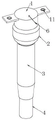
图3为本实用新型的立体示意图;Fig. 3 is the three-dimensional schematic diagram of the utility model;
图4为图1中A处结构放大示意图;Fig. 4 is the enlarged schematic diagram of the structure at place A in Fig. 1;
图5为图1中B处结构放大示意图;Fig. 5 is the enlarged schematic diagram of the structure at B in Fig. 1;
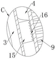
图6为图1中C处结构放大示意图;Fig. 6 is a schematic enlarged view of the structure at C in Fig. 1;
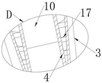
图7为图1中D处结构放大示意图。FIG. 7 is an enlarged schematic view of the structure at D in FIG. 1 .
图中:1、安装块;2、气囊;3、安装管;4、活塞筒;5、连接板;6、进气管;7、定位杆;8、隔板;9、减震弹簧;10、连接块;11、安装孔;12、定位槽;13、安装垫圈;14、紧固环;15、限位块;16、环形槽;17、密封垫圈;18、加强筋。In the figure: 1. Installation block; 2. Airbag; 3. Installation pipe; 4. Piston cylinder; 5. Connecting plate; 6. Air intake pipe; 7. Positioning rod; Connection block; 11, installation hole; 12, positioning groove; 13, installation washer; 14, fastening ring; 15, limit block; 16, annular groove; 17, sealing washer; 18, reinforcing rib.
具体实施方式Detailed ways
下文结合附图和具体实施例对本实用新型的技术方案做进一步说明。The technical solutions of the present invention will be further described below with reference to the accompanying drawings and specific embodiments.
实施例1Example 1
如图1、图2、图3、图5、图6和图7所示,本实用新型提出的一种汽车用气囊活塞连接结构电动自行车电机检测装置,包括安装块1、气囊2、安装管3、活塞筒4和进气管6,安装管3的内部设置有导向密封机构,导向密封机构包括安装在安装管3内部的两个限位块15,限位块15的外部开设有环形槽16,限位块15与活塞筒4的外部相贴合,安装管3的内部安装有多个密封垫圈17,密封垫圈17与活塞筒4的外部紧密贴合;As shown in Fig. 1, Fig. 2, Fig. 3, Fig. 5, Fig. 6 and Fig. 7, an electric bicycle motor detection device with an airbag piston connection structure for automobiles proposed by the present utility model includes a
气囊2与安装块1的内部相连接,安装块1的内部设置有紧固环14,紧固环14与气囊2的外部相抵紧,气囊2远离安装块1的一端与安装管3的内部相连接,活塞筒4与安装管3的内部活动连接,安装块1的内部安装有定位杆7,定位杆7远离安装块1的一端贯穿至活塞筒4的内部;The
定位杆7的外部安装有隔板8,隔板8的外部安装有减震弹簧9,减震弹簧9远离隔板8的一端与活塞筒4的内部相连接,定位杆7贯穿至活塞筒4内部的端部安装有连接块10。A
基于实施例一的一种汽车用气囊活塞连接结构工作原理是,汽车在行驶的过程中受到外界的振动时,活塞筒4会向着安装管3的内部收缩,活塞筒4在收缩的过程中会拉动减震弹簧9,通过减震弹簧9自身的弹力实现对振动的减震,并且活塞筒4在上下移动的过程中会与限位块15的外部相接触,通过限位块15实现对活塞筒4的导向作用,同时密封垫圈17设置为三道,从而可以避免安装管3内部的高压气体发生泄漏,同时密封垫圈17也起到对活塞筒4的导向作用,保证了活塞筒4的移动的准确性,从而保证了装置的整体使用寿命。The working principle of an airbag piston connection structure for an automobile based on the first embodiment is that when the automobile is subjected to external vibrations during driving, the
实施例二
如图1和图4所示,基于实施例一的基础上,安装块1的外部还设置有用于对安装块1进行安装的固定机构,固定机构包括安装在安装块1外部的两个连接板5,两个连接板5呈对称设置,连接板5的外部开设有安装孔11,连接板5的外部开设有定位槽12,定位槽12的内部设置有安装垫圈13,连接板5与安装块1的外部之间设置有加强筋18,进气管6与安装块1的内部相连通,安装块1、气囊2、安装管3和活塞筒4共同组成气囊活塞结构,然后通过连接板5进行快速安装。As shown in FIG. 1 and FIG. 4 , based on the first embodiment, a fixing mechanism for installing the
本实施例中这样设计,在遇到较为复杂的路段,通过进气管6可以将外界的高压气体泵入到安装块1的内部,安装块1内部的压力上升,从而使得气囊2开始膨胀,气囊2在膨胀的过程中相对与活塞筒4会向运动,从而在对车身升高的过程还实现对减震弹簧9的挤压,进而使得装置的悬挂变硬,更容易通过复杂路段;This embodiment is designed in this way, when encountering a relatively complicated road section, the high-pressure gas from the outside can be pumped into the interior of the mounting
并且在对安装块1进行安装的过程中,将螺丝插入到安装孔11中,再将螺丝与汽车底盘相连接,就可以实现对安装块1的固定,并且通过加强筋18可以增强连接板5与安装块1之间的强度,避免连接板5在长时间的使用过程中出现损坏。And in the process of installing the mounting
以上,仅为本实用新型较佳的具体实施方式,但本实用新型的保护范围并不局限于此,任何熟悉本技术领域的技术人员在本实用新型揭露的技术范围内,根据本实用新型的技术方案及其实用新型构思加以等同替换或改变,都应涵盖在本实用新型的保护范围之内。The above are only preferred specific embodiments of the present invention, but the protection scope of the present invention is not limited to this. The technical solution and its utility model concept are equivalently replaced or changed, and should be covered within the protection scope of the present utility model.
Claims (6)
Priority Applications (1)
| Application Number | Priority Date | Filing Date | Title |
|---|---|---|---|
| CN202121735239.5U CN216642931U (en) | 2021-07-28 | 2021-07-28 | An automobile airbag piston connection structure |
Applications Claiming Priority (1)
| Application Number | Priority Date | Filing Date | Title |
|---|---|---|---|
| CN202121735239.5U CN216642931U (en) | 2021-07-28 | 2021-07-28 | An automobile airbag piston connection structure |
Publications (1)
| Publication Number | Publication Date |
|---|---|
| CN216642931U true CN216642931U (en) | 2022-05-31 |
Family
ID=81722760
Family Applications (1)
| Application Number | Title | Priority Date | Filing Date |
|---|---|---|---|
| CN202121735239.5U Active CN216642931U (en) | 2021-07-28 | 2021-07-28 | An automobile airbag piston connection structure |
Country Status (1)
| Country | Link |
|---|---|
| CN (1) | CN216642931U (en) |
Cited By (1)
| Publication number | Priority date | Publication date | Assignee | Title |
|---|---|---|---|---|
| CN119755234A (en) * | 2025-01-20 | 2025-04-04 | 南京依维柯汽车有限公司 | Air suspension shock absorbing device for intelligent driving vehicle |
-
2021
- 2021-07-28 CN CN202121735239.5U patent/CN216642931U/en active Active
Cited By (2)
| Publication number | Priority date | Publication date | Assignee | Title |
|---|---|---|---|---|
| CN119755234A (en) * | 2025-01-20 | 2025-04-04 | 南京依维柯汽车有限公司 | Air suspension shock absorbing device for intelligent driving vehicle |
| CN119755234B (en) * | 2025-01-20 | 2025-11-18 | 南京依维柯汽车有限公司 | An air suspension damping device for intelligent driving vehicles |
Similar Documents
| Publication | Publication Date | Title |
|---|---|---|
| WO2019206055A1 (en) | Damping mechanism for shock absorber and combined hydraulic-pneumatic damping-based shock absorber employing same | |
| CN218343208U (en) | Suspension damping auxiliary structure for automobile balancing rod | |
| CN115013464B (en) | Oil-gas spring and vehicle suspension device | |
| CN217207477U (en) | Pneumatic suspension structure of motorcycle | |
| CN220726953U (en) | Double-sealing top seat of air spring, damper and vehicle | |
| CN201944179U (en) | Vehicle shock absorber | |
| CN104500636A (en) | Sensing variable-frequency vibration absorber | |
| CN218094008U (en) | Air chamber structure in shock absorber | |
| CN210265640U (en) | But height-adjusting's integral type air spring bumper shock absorber | |
| CN107989947B (en) | A multi-piston damping adjustable shock absorber mechanism | |
| CN215908302U (en) | Air bag type compression force adjustable shock absorber | |
| CN113124083B (en) | Hydro-pneumatic spring and car | |
| CN200995599Y (en) | Oil-gas separated spring for suspension of vehicle | |
| CN212775314U (en) | Single-circulation-structure oil pressure damper guide cover assembly for high-speed motor train unit | |
| CN202707897U (en) | Automobile shock absorber provided with flanging sealing mechanism | |
| CN221347704U (en) | High-performance spring damper | |
| CN223563354U (en) | A type of suspended hydraulic cylinder | |
| CN209813657U (en) | Air suspension system for vehicle | |
| CN223469639U (en) | A single-tube hydraulic shock absorber suitable for electric bicycles | |
| CN223178043U (en) | An air shock absorber | |
| CN223136792U (en) | Motorcycle air suspension damper and motorcycle damping control system | |
| CN222166432U (en) | A vehicle shock absorber piston rod air tightness testing device | |
| CN223459799U (en) | An air spring shock absorber | |
| CN223294120U (en) | An integrated double-tube nitrogen shock absorber structure | |
| CN111692262A (en) | Hydro-pneumatic suspension |
Legal Events
| Date | Code | Title | Description |
|---|---|---|---|
| GR01 | Patent grant | ||
| GR01 | Patent grant | ||
| CP01 | Change in the name or title of a patent holder | ||
| CP01 | Change in the name or title of a patent holder |
Address after: No. 988, Maicun section, DanJin Road, Danyang City, Zhenjiang City, Jiangsu Province, 212300 Patentee after: Jiangsu Lianchuang Auto Accessories Co.,Ltd. Address before: No. 988, Maicun section, DanJin Road, Danyang City, Zhenjiang City, Jiangsu Province, 212300 Patentee before: DANYANG LIANCHUANG AUTO ACCESSORIES CO.,LTD. |
|
| TR01 | Transfer of patent right | ||
| TR01 | Transfer of patent right |
Effective date of registration: 20241017 Address after: 212000 Jiepai Town JieXi Industrial Park, Danyang City, Zhenjiang City, Jiangsu Province Patentee after: Danyang Xinfenghua Automotive Parts Co.,Ltd. Country or region after: China Address before: No. 988, Maicun section, DanJin Road, Danyang City, Zhenjiang City, Jiangsu Province, 212300 Patentee before: Jiangsu Lianchuang Auto Accessories Co.,Ltd. Country or region before: China |