CN216640477U - Water inlet flow channel template - Google Patents
Water inlet flow channel template Download PDFInfo
- Publication number
- CN216640477U CN216640477U CN202123052958.XU CN202123052958U CN216640477U CN 216640477 U CN216640477 U CN 216640477U CN 202123052958 U CN202123052958 U CN 202123052958U CN 216640477 U CN216640477 U CN 216640477U
- Authority
- CN
- China
- Prior art keywords
- water inlet
- mold
- inlet channel
- steel pipe
- template
- Prior art date
- Legal status (The legal status is an assumption and is not a legal conclusion. Google has not performed a legal analysis and makes no representation as to the accuracy of the status listed.)
- Active
Links
- XLYOFNOQVPJJNP-UHFFFAOYSA-N water Substances O XLYOFNOQVPJJNP-UHFFFAOYSA-N 0.000 title claims abstract description 53
- 229910000831 Steel Inorganic materials 0.000 claims abstract description 50
- 239000010959 steel Substances 0.000 claims abstract description 50
- 239000002023 wood Substances 0.000 claims description 13
- 239000005028 tinplate Substances 0.000 claims description 3
- 238000000465 moulding Methods 0.000 claims description 2
- 238000010276 construction Methods 0.000 abstract description 15
- 238000009415 formwork Methods 0.000 description 20
- 238000009434 installation Methods 0.000 description 8
- 238000000034 method Methods 0.000 description 7
- 229910001037 White iron Inorganic materials 0.000 description 6
- 238000010586 diagram Methods 0.000 description 6
- 230000000694 effects Effects 0.000 description 5
- 238000004519 manufacturing process Methods 0.000 description 4
- 238000005452 bending Methods 0.000 description 3
- 238000009413 insulation Methods 0.000 description 2
- 235000017166 Bambusa arundinacea Nutrition 0.000 description 1
- 235000017491 Bambusa tulda Nutrition 0.000 description 1
- 241001330002 Bambuseae Species 0.000 description 1
- 235000015334 Phyllostachys viridis Nutrition 0.000 description 1
- 239000011425 bamboo Substances 0.000 description 1
- 239000000463 material Substances 0.000 description 1
- 239000011120 plywood Substances 0.000 description 1
- 230000007306 turnover Effects 0.000 description 1
Images


Classifications
-
- Y—GENERAL TAGGING OF NEW TECHNOLOGICAL DEVELOPMENTS; GENERAL TAGGING OF CROSS-SECTIONAL TECHNOLOGIES SPANNING OVER SEVERAL SECTIONS OF THE IPC; TECHNICAL SUBJECTS COVERED BY FORMER USPC CROSS-REFERENCE ART COLLECTIONS [XRACs] AND DIGESTS
- Y02—TECHNOLOGIES OR APPLICATIONS FOR MITIGATION OR ADAPTATION AGAINST CLIMATE CHANGE
- Y02E—REDUCTION OF GREENHOUSE GAS [GHG] EMISSIONS, RELATED TO ENERGY GENERATION, TRANSMISSION OR DISTRIBUTION
- Y02E10/00—Energy generation through renewable energy sources
- Y02E10/20—Hydro energy
Landscapes
- Forms Removed On Construction Sites Or Auxiliary Members Thereof (AREA)
Abstract
一种进水流道模板,包括进水流道内模、钢管扣件支撑体系;所述进水流道内模与进水流道的内壁相适应;钢管扣件支撑体系设置在进水流道内模的内腔室中;所述进水流道内模包括内圈骨架,内圈骨架与进水流道断面对应并分多个沿进水流道内模延伸方向间隔布置,内圈骨架内侧与钢管扣件支撑体系可拆卸连接;内圈骨架外围与木模骨架连接,木模骨架外包覆有模板。本实用新型提供的一种进水流道模板,可以提高进水流道的施工进度和施工质量。

A water inlet channel template, comprising a water inlet channel inner mold and a steel pipe fastener support system; the water inlet channel inner mold is adapted to the inner wall of the water inlet channel; the steel pipe fastener support system is arranged in the inner cavity of the water inlet channel inner mold The inner mold of the water inlet channel includes an inner ring frame, and the inner ring frame corresponds to the cross section of the water inlet channel and is arranged in multiple intervals along the extending direction of the inner mold of the water inlet channel, and the inner side of the inner ring frame is detachably connected with the steel pipe fastener support system; The periphery of the ring skeleton is connected with the wooden mold skeleton, and the wooden mold skeleton is covered with a template. The water inlet channel template provided by the utility model can improve the construction progress and construction quality of the water inlet channel.
Description
技术领域technical field
本实用新型涉及模板,尤其是一种进水流道模板。The utility model relates to a template, in particular to a water inlet flow channel template.
背景技术Background technique
在对水利工程的泵站进水流道进行施工时,通常采用专门定制的定型钢模板,或现场制作安装木模板。定型钢模板一般造价不菲且周转效率低,施工过程中保温效果差,不利于混凝土裂缝控制;现场制作安装木模板受施工现场条件影响较大,常常与施工现场其他施工项目发生冲突,造成施工进度缓慢,且现场制作木模没有统一的荷载标准,施工质量较难保证。When constructing the water inlet channel of the pump station of the water conservancy project, the specially customized shaped steel formwork is usually used, or the wooden formwork is produced and installed on site. Shaped steel formwork is generally expensive and has low turnover efficiency. During the construction process, the thermal insulation effect is poor, which is not conducive to the control of concrete cracks; the on-site production and installation of wooden formwork is greatly affected by the construction site conditions, and often conflicts with other construction projects on the construction site, resulting in construction The progress is slow, and there is no uniform load standard for the on-site production of wood molds, so it is difficult to guarantee the construction quality.
发明内容SUMMARY OF THE INVENTION
本实用新型所要解决的技术问题是提供一种进水流道模板,制作简单、安装方便、经济实用、效果良好,模板制作均在加工厂内完成,现场仅需进行简单安装即可,可以提高进水流道的施工进度和施工质量。The technical problem to be solved by the utility model is to provide a water inlet channel template, which is simple to manufacture, convenient to install, economical and practical, and has good effect. The construction progress and construction quality of the water channel.
为解决上述技术问题,本实用新型所采用的技术方案是:In order to solve the above-mentioned technical problems, the technical scheme adopted by the present utility model is:
一种进水流道模板,包括进水流道内模、钢管扣件支撑体系;所述进水流道内模与进水流道的内壁相适应;钢管扣件支撑体系设置在进水流道内模的内腔室中;所述进水流道内模包括内圈骨架,内圈骨架与进水流道断面对应并分多个沿进水流道内模延伸方向间隔布置,内圈骨架内侧与钢管扣件支撑体系可拆卸连接;内圈骨架外围与木模骨架连接,木模骨架外包覆有模板;所述进水流道内模包括引流段内模和端头段内模,其中,引流段内模由四个半幅内模吊装拼接而成;端头段内模整体制作完成。A water inlet channel template, comprising a water inlet channel inner mold and a steel pipe fastener support system; the water inlet channel inner mold is adapted to the inner wall of the water inlet channel; the steel pipe fastener support system is arranged in the inner cavity of the water inlet channel inner mold The inner mold of the water inlet channel includes an inner ring frame, and the inner ring frame corresponds to the cross section of the water inlet channel and is arranged in multiple intervals along the extending direction of the inner mold of the water inlet channel, and the inner side of the inner ring frame is detachably connected with the steel pipe fastener support system; The outer periphery of the ring frame is connected with the wood mold frame, and the wood mold frame is covered with a template; the inner mold of the water inlet channel includes the inner mold of the drainage section and the inner mold of the end section, wherein the inner mold of the drainage section is hoisted and spliced by four half-width inner molds The inner mold of the end section is completed as a whole.
所述引流段内模的木模骨架为多个第一纵向木方,第一纵向木方分多个沿引流段内模内壁轨迹方向分布。The wooden mold skeleton of the inner mold of the drainage section is a plurality of first longitudinal wooden squares, and the first longitudinal wooden squares are divided into a plurality of distributed along the track direction of the inner wall of the inner mold of the drainage section.
所述端头段内模的木模骨架包括多个木板肋条骨架,木板肋条骨架与进水流道端头段断面对应并分多个沿端头段内模延伸方向间隔布置;相邻的木板肋条骨架之间采用多个第二纵向木方连接填充。The wood mold skeleton of the inner mold of the end section includes a plurality of wood rib skeletons, which correspond to the cross-section of the end section of the water inlet channel and are arranged in a plurality of intervals along the extension direction of the inner mold of the end section; adjacent wood rib skeletons A plurality of second longitudinal wooden square connections are used to fill in between.
所述模板包括内层的成型木模板和外层的白铁皮。The formwork includes a formed wooden formwork on the inner layer and a tinplate on the outer layer.
所述内圈骨架为钢管,内圈骨架与钢管扣件支撑体系通过钢管扣件可拆卸搭接。The inner ring frame is a steel pipe, and the inner ring frame and the steel pipe fastener support system are detachably lapped through the steel pipe fastener.
本实用新型一种进水流道模板,具有以下技术效果:The utility model is a water inlet flow channel template, which has the following technical effects:
1)、造价低廉、操作方便。1), low cost, easy to operate.
2)、取材方便、可复制性强。2), the material is convenient and reproducible.
3)、采用整体制作完成后现场拼接,减少了施工现场制模的工作量,压缩了施工时间,节约施工成本。3), the use of on-site splicing after the overall production is completed, reduces the workload of the construction site mold making, compresses the construction time, and saves the construction cost.
4)、木模板保温效果更好,且模板外层采用白铁皮能更好的保证流道砼浇筑效果,提高工程质量。4) The thermal insulation effect of the wooden formwork is better, and the outer layer of the formwork is made of white iron sheet, which can better ensure the pouring effect of the runner concrete and improve the quality of the project.
5)、钢管扣件支撑体系类似于脚手架结构,钢管扣件支撑体系的横向钢管和纵向钢管之间通过钢管扣件可拆卸连接,钢管扣件支撑体系的纵向钢管与内圈骨架也通过钢管扣件可拆卸连接。钢架结构支撑更加稳定,同时拆卸更加方便、快速,且不会破坏其结构。另外,钢管扣件支撑体系为现有建筑常用施工工具,取用很方便,无需另外加工。5) The steel pipe fastener support system is similar to the scaffolding structure. The horizontal steel pipe and the longitudinal steel pipe of the steel pipe fastener support system are detachably connected by steel pipe fasteners, and the longitudinal steel pipe and the inner ring frame of the steel pipe fastener support system are also connected by steel pipe fasteners. Pieces of detachable connection. The support of the steel frame structure is more stable, and the disassembly is more convenient and fast, and the structure will not be damaged. In addition, the steel pipe fastener support system is a commonly used construction tool in existing buildings, which is easy to use and does not require additional processing.
附图说明Description of drawings
下面结合附图和实施例对本实用新型作进一步说明:Below in conjunction with accompanying drawing and embodiment, the utility model is further described:
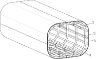
图1为本实用新型中引流段内模的局部示意图。Fig. 1 is a partial schematic diagram of the inner mold of the drainage section in the utility model.
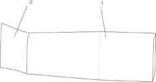
图2为本实用新型中进水流道内模的外部结构示意图。FIG. 2 is a schematic diagram of the external structure of the inner mold of the water inlet channel in the utility model.
图3为本实用新型中进水流道内模的外部结构示意图。FIG. 3 is a schematic diagram of the external structure of the inner mold of the water inlet flow channel in the utility model.
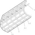
图4为本实用新型中引流段内模的半幅内模的结构示意图。FIG. 4 is a schematic structural diagram of the half-width inner mold of the drainage section inner mold in the utility model.
图5为本实用新型中端头段内模的木模骨架的结构示意图。FIG. 5 is a schematic structural diagram of the wooden mold skeleton of the inner mold of the middle end section of the utility model.
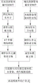
图6为本实用新型的施工流程框图。FIG. 6 is a block diagram of the construction flow of the utility model.
图中:引流段内模1,端头段内模2,钢管扣件支撑体系3,内圈骨架4,木模骨架5,第一纵向木方5.1,木板肋条骨架5.2,第二纵向木方5.3,模板6,成型木模板6.1,白铁皮6.2。In the figure: the
具体实施方式Detailed ways
一种进水流道模板,包括进水流道内模、钢管扣件支撑体系3,其中,进水流道内模与进水流道的内壁相适应,钢管扣件支撑体系3设置在进水流道内模的内腔室中。A water inlet channel template, comprising a water inlet channel inner mold and a steel pipe
如图2-3所示,所述进水流道内模在长度方向上分为引流段内模1和端头段内模2。引流段内模1主要是进水池末端方形截面逐渐变为倒圆角截面的进口段,在宽度方向上分为中心对称布置的四个半幅,每个半幅内模向中心对称点延伸设置且截面逐渐变小,四个半幅内模吊装拼接成一个引流段内模1。端头段内模2主要是向上弯肘设置的且截面逐渐变成圆的与水泵连接的出口段,采用整体制作吊装。本申请的进水流道内模可不限于上述具体结构,也可为其他异性结构,整体结构及整体安装方式同样适用其他异性结构。As shown in Fig. 2-3, the inner mold of the water inlet channel is divided into the
如图1、图4所示,所述引流段内模1的每个半幅内模包括多个沿其延伸方向间隔布置的内圈骨架4,内圈骨架4为钢管。内圈骨架4外围分布有多个第一纵向木方5.1,每个第一纵向木方5.1沿引流段内模1延长方向布置,多个第一纵向木方5.1沿内圈骨架4外围轨迹分布。在第一纵向木方5.1外围固定有成型木模板6.1,成型木模板6.1外围固定有白铁皮6.2。As shown in FIG. 1 and FIG. 4 , each half-width inner mold of the
上述各部分零件之间采用钢钉连接。The above parts are connected by steel nails.
上述零件中,内圈骨架4根据进水流道引流段设计图纸断面采用切割+弯曲工艺弯曲成型,通过在钢管上切割不同深度、不同间距的切缝使得钢管具有更好的弯曲空间,能弯曲成型与设计断面相适应的线型。各个内圈骨架4互相之间通过钢管扣件与钢管扣件支撑体系3(横向、纵向钢管搭接而成的架体结构,与脚手架类似,图中只画了一根纵向钢管,其他未画出)中的纵向钢管连接。第一纵向木方5.1以间距100mm均匀布置于内圈骨架4外围,纵向搭接以500mm控制。Among the above-mentioned parts, the
多个上述构件组成一个半幅内模,四个半幅内模拼接组成一个引流段内模。A plurality of the above-mentioned components form a half-width inner mold, and four half-width inner molds are spliced to form a drainage section inner mold.
引流段内模1的白铁皮6.2以及钢管扣件支撑体系3在拼接4个相同半幅内模时进行现场搭设,其余部分均在厂房内完成。The white iron sheet 6.2 of the
如图5所示,图中仅仅画出木模骨架5的结构,但其他零件的安装方式及位置与引流段内模1相似。所述端头段内模2包括多个沿其延伸方向间隔布置的内圈骨架4,内圈骨架4为钢管。在内圈骨架4外围固定有木板肋条骨架5.2,相邻的木板肋条骨架5.2之间固定有第二纵向木方5.3,木板肋条骨架5.2、第二纵向木方5.3共同构成木模骨架5,木模骨架5外围固定有成型木模板2.4,成型木模板2.5外围固定有白铁皮6.2。上述各部分零件之间采用钢钉连接。As shown in FIG. 5 , only the structure of the wooden mold frame 5 is shown in the drawing, but the installation methods and positions of other parts are similar to those of the
上述内圈骨架4根据进水流道端头段设计图纸断面采用切割+弯曲工艺弯曲成型,内圈骨架4互相之间通过钢管扣件与钢管扣件支撑体系3中的纵向钢管连接。The above-mentioned
木板肋条骨架5.2根据进水流道端头段设计图纸断面采用切割+拼接工艺制作成型,在木模板上描画出与设计断面相适应的线型,通过电锯切割成所需的木板肋条骨架。每个端头段内模2共包含7个木板肋条骨架5.2,木板肋条骨架5.2之间采用不同长度的第二纵向木方5.3以间距100mm均匀布置。通过第二纵向木方5.3的长度和角度调整木板肋条骨架5.2所处空间位置。5.2 The plank rib skeleton is formed according to the design drawing of the end section of the water inlet channel by cutting + splicing process, and the line shape suitable for the design section is drawn on the wooden template, and the required plank rib skeleton is cut by a chainsaw. Each end section inner mold 2 includes a total of 7 plank rib frames 5.2, and second longitudinal wooden squares 5.3 of different lengths are evenly arranged between the plank rib frames 5.2 with a spacing of 100mm. The spatial position of the wooden rib frame 5.2 is adjusted by the length and angle of the second longitudinal wooden square 5.3.
多个上述构件组成一个端头段内模2。端头段内模2采用整体制作,拼接端头段内模2的同时在端头段内模2的腔室内搭设钢管扣件支撑体系3,与内圈骨架4连接牢固。端头段内模2的制模工作均在厂房内完成。A plurality of the above-mentioned components constitute an end section inner mold 2 . The inner mold 2 of the end section is made as a whole. When splicing the inner mold 2 of the end section, a steel pipe
成型木模板6.1采用竹胶板制成,成型木模板6.1根据木模骨架5形状裁剪切割,引流段成型木模板与木模骨架5外围的第一纵向木方5.1之间通过钢钉连接;端头段成型木模板与木板肋条骨架5.2、第二纵向木方5.3之间通过钢钉连接。The forming wooden formwork 6.1 is made of bamboo plywood, the forming wooden formwork 6.1 is cut and cut according to the shape of the wooden formwork skeleton 5, and the forming wooden formwork of the drainage section and the first longitudinal wooden square 5.1 on the periphery of the wooden formwork skeleton 5 are connected by steel nails; The forming wooden formwork of the head section is connected with the rib frame 5.2 of the wooden board and the second longitudinal wooden square 5.3 by steel nails.
引流段内模1拼装时,先将下半部分的两个半幅内模吊运至安装位置,并安装部分横向钢管扣件支撑初步定位,再将上半部分的两个半幅内模吊运至安装位置,并安装完善钢管扣件支撑体系3,与内圈骨架4连接牢固。When the
引流段内模1安装完成后,将端头段内模2整体吊装至安装位置,端头段内模2与引流段内模1连接处的木方及骨架之间采用钢钉连接,端头段内模2腔室内的钢管扣件支撑体系3与引流段内模1腔室内的钢管扣件支撑体系3通过扣件连接成整体,构成完整的进水流道模板。After the installation of the
模板拼装完成后,根据构件形状裁剪白铁皮6.2,白铁皮6.2与成型木模板6.1之间通过钢钉连接。After the formwork is assembled, cut the white iron sheet 6.2 according to the shape of the component, and connect the white iron sheet 6.2 and the formed wooden formwork 6.1 by steel nails.
Claims (5)
Priority Applications (1)
| Application Number | Priority Date | Filing Date | Title |
|---|---|---|---|
| CN202123052958.XU CN216640477U (en) | 2021-12-07 | 2021-12-07 | Water inlet flow channel template |
Applications Claiming Priority (1)
| Application Number | Priority Date | Filing Date | Title |
|---|---|---|---|
| CN202123052958.XU CN216640477U (en) | 2021-12-07 | 2021-12-07 | Water inlet flow channel template |
Publications (1)
| Publication Number | Publication Date |
|---|---|
| CN216640477U true CN216640477U (en) | 2022-05-31 |
Family
ID=81738694
Family Applications (1)
| Application Number | Title | Priority Date | Filing Date |
|---|---|---|---|
| CN202123052958.XU Active CN216640477U (en) | 2021-12-07 | 2021-12-07 | Water inlet flow channel template |
Country Status (1)
| Country | Link |
|---|---|
| CN (1) | CN216640477U (en) |
Cited By (1)
| Publication number | Priority date | Publication date | Assignee | Title |
|---|---|---|---|---|
| CN119041355A (en) * | 2024-11-02 | 2024-11-29 | 中交第四航务工程局有限公司 | Water delivery gallery template structure and construction method thereof |
-
2021
- 2021-12-07 CN CN202123052958.XU patent/CN216640477U/en active Active
Cited By (1)
| Publication number | Priority date | Publication date | Assignee | Title |
|---|---|---|---|---|
| CN119041355A (en) * | 2024-11-02 | 2024-11-29 | 中交第四航务工程局有限公司 | Water delivery gallery template structure and construction method thereof |
Similar Documents
| Publication | Publication Date | Title |
|---|---|---|
| CN218668057U (en) | Integrated form mould shell superimposed shear wall | |
| CN216276905U (en) | Regular hexagon fair-faced concrete column steel-wood mixed template reinforcing system | |
| CN111535347A (en) | A kind of prefabricated plate tire membrane nested connection structure and construction method | |
| CN119801247A (en) | Construction method of concrete inner formwork support system for the diffusion section of super large wind tunnel | |
| CN219837952U (en) | Arc concrete wall template | |
| CN203640278U (en) | Stair construction die shelf | |
| CN102777028B (en) | Construction method of pseudo-classic architecture cornice rafter polyphenyl template system | |
| CN207959244U (en) | Prefabricated assembling type reinforced frame raft foundation alter-pouring strips mould plate | |
| CN201671323U (en) | Combination formwork for building walls | |
| CN215254581U (en) | Tool type beam column joint angle mould | |
| CN110017141A (en) | A kind of ultra-deep shaft concrete ring grid beam quick template supporting system and its construction method | |
| CN210049579U (en) | Formwork system of concrete thin-shell dome structure | |
| CN220828037U (en) | Truss floor carrier plate supporting structure | |
| CN221481158U (en) | Combined grid hollow floor core die supporting structure | |
| CN220580181U (en) | Novel assembled umbrella-shaped structure | |
| CN112443159A (en) | Template tapping-free clamp and construction method thereof | |
| CN111395591A (en) | Side-lying thin-walled arc circular hole concrete shear wall, support system and construction method | |
| CN217439305U (en) | Prefabricated building carrier plate of built-in steel bar truss of assembled | |
| CN217079684U (en) | Split type form removal-free concrete hollow structure | |
| CN214143782U (en) | Combined pile foundation bearing platform mould | |
| CN107605156B (en) | Method for reinforcing chamfer template | |
| CN210797967U (en) | Novel precast concrete module formwork constructional column structure | |
| CN108660930B (en) | Bottom template integral hoisting method | |
| CN114941434A (en) | Construction method of cast-in-situ bare concrete hyperboloid special-shaped decorative plate | |
| CN203594224U (en) | Novel semi-fabricated formwork |
Legal Events
| Date | Code | Title | Description |
|---|---|---|---|
| GR01 | Patent grant | ||
| GR01 | Patent grant |