CN216635115U - A vertical push type building foam board forming mold - Google Patents
A vertical push type building foam board forming mold Download PDFInfo
- Publication number
- CN216635115U CN216635115U CN202122069148.9U CN202122069148U CN216635115U CN 216635115 U CN216635115 U CN 216635115U CN 202122069148 U CN202122069148 U CN 202122069148U CN 216635115 U CN216635115 U CN 216635115U
- Authority
- CN
- China
- Prior art keywords
- foam board
- push
- bottom end
- propelling movement
- connecting rod
- Prior art date
- Legal status (The legal status is an assumption and is not a legal conclusion. Google has not performed a legal analysis and makes no representation as to the accuracy of the status listed.)
- Active
Links
- 239000006260 foam Substances 0.000 title claims abstract description 41
- 230000007246 mechanism Effects 0.000 claims abstract description 34
- 238000010276 construction Methods 0.000 claims description 4
- 238000004513 sizing Methods 0.000 claims 3
- 238000010586 diagram Methods 0.000 description 5
- 238000009413 insulation Methods 0.000 description 3
- 230000013011 mating Effects 0.000 description 3
- 238000000034 method Methods 0.000 description 3
- 230000006835 compression Effects 0.000 description 2
- 238000007906 compression Methods 0.000 description 2
- 238000010438 heat treatment Methods 0.000 description 2
- 239000011324 bead Substances 0.000 description 1
- 230000009286 beneficial effect Effects 0.000 description 1
- 239000002131 composite material Substances 0.000 description 1
- 238000005034 decoration Methods 0.000 description 1
- 238000005516 engineering process Methods 0.000 description 1
- 229920006248 expandable polystyrene Polymers 0.000 description 1
- 239000004088 foaming agent Substances 0.000 description 1
- 239000007788 liquid Substances 0.000 description 1
- 239000010687 lubricating oil Substances 0.000 description 1
- 238000012423 maintenance Methods 0.000 description 1
- 238000004519 manufacturing process Methods 0.000 description 1
- 238000000465 moulding Methods 0.000 description 1
- 239000002994 raw material Substances 0.000 description 1
- 230000000630 rising effect Effects 0.000 description 1
- 238000007493 shaping process Methods 0.000 description 1
- 239000002699 waste material Substances 0.000 description 1
Images


Landscapes
- Moulds, Cores, Or Mandrels (AREA)
Abstract
本实用新型涉及建筑泡沫板技术领域,具体地说,涉及一种垂直推送式建筑泡沫板用定型模具。其包括模具成型机构以及安装在模具成型机构底端的推送机构,模具成型机构包括底板,底板顶端设置有若干支杆,支杆顶端设置有模具箱,模具箱内端设置有推送槽,推送机构包括液压杆,液压杆底端与底板顶端连接,液压杆顶端设置有连接杆,连接杆顶端设置有推动块,推送块与推送槽插接配合。本实用新型通过设置的推送机构,具体使用时,当建筑泡沫板在其模具箱内端进行挤压成型后,通过液压杆带动连接杆向上移动,从而带动推送块向上移动,推送块将其成型后的建筑泡沫板向上垂直推出模具箱顶端,实现自动搬运,无需人工手动进行提拉,减少其操作人员工作量。
The utility model relates to the technical field of building foam boards, in particular to a setting mould for vertical push-type building foam boards. It includes a mold forming mechanism and a push mechanism installed at the bottom end of the mold forming mechanism. The mold forming mechanism includes a bottom plate, the top of the bottom plate is provided with a number of support rods, the top of the support rod is provided with a mold box, the inner end of the mold box is provided with a push groove, and the push mechanism includes: The bottom end of the hydraulic rod is connected with the top end of the bottom plate, the top end of the hydraulic rod is provided with a connecting rod, the top end of the connecting rod is provided with a push block, and the push block is inserted and matched with the push groove. The utility model adopts the push mechanism provided, and in specific use, after the building foam board is extruded at the inner end of the mold box, the hydraulic rod drives the connecting rod to move upward, thereby driving the push block to move upward, and the push block shapes it. The rear building foam board is pushed up and vertically to the top of the mold box to realize automatic handling, without manual lifting and pulling, reducing the workload of its operators.
Description
技术领域technical field
本实用新型涉及建筑泡沫板技术领域,具体地说,涉及一种垂直推送式建筑泡沫板用定型模具。The utility model relates to the technical field of building foam boards, in particular to a setting mould for vertical push-type building foam boards.
背景技术Background technique
建筑泡沫板又名泡沫板、EPS板是由含有挥发性液体发泡剂的可发性聚苯乙烯珠粒,经加热预发后在模具中加热成型的白色物体,其有微细闭孔的结构特点,主要用于建筑墙体,屋面保温,复合板保温,冷库、空调、车辆、船舶的保温隔热,地板采暖,装潢雕刻等用途非常广泛。Building foam board, also known as foam board and EPS board, is a white object made of expandable polystyrene beads containing a volatile liquid foaming agent and heated in a mold after pre-heating. It has a fine closed-cell structure. It is mainly used for building wall, roof insulation, composite board insulation, cold storage, air conditioner, vehicle, ship insulation, floor heating, decoration carving and other applications.
建筑泡沫板再生产过程,首先需要对其进行定型处理,通过模具进行多种规则的建筑泡沫板定型,而现有的建筑泡沫板定型模具在定型完成后,由于模具与建筑泡沫板完成一致,导致在进行取出时,需要操作人员手动进行取出,由于建筑泡沫板表面较为光滑,难以进行施力,需要多人协作才能进行提取,导致工作效率大大降低。In the process of reproducing the building foam board, it needs to be shaped first, and the building foam board with various rules is shaped through the mold. After the existing building foam board shaping mold is completed, because the mold is consistent with the building foam board, resulting in When taking out, the operator needs to take out manually. Because the surface of the building foam board is relatively smooth, it is difficult to apply force, and it requires the cooperation of many people to extract, which greatly reduces the work efficiency.
实用新型内容Utility model content
本实用新型的目的在于提供一种垂直推送式建筑泡沫板用定型模具,以解决上述背景技术中提出的问题。The purpose of the present utility model is to provide a vertical push-type building foam board forming mold, so as to solve the problems raised in the above-mentioned background technology.
为实现上述目的,本实用新型提供一种垂直推送式建筑泡沫板用定型模具,包括模具成型机构以及安装在所述模具成型机构底端的推送机构,所述模具成型机构包括支撑板面,所述支撑板面顶端设置有若干支杆,所述支杆顶端设置有模具箱,所述模具箱内侧底端设置有推送槽,所述推送机构包括液压杆,所述液压杆底端与所述支撑板面顶端固定连接,所述液压杆顶端设置有连接杆,所述连接杆顶端设置有推送块,所述推送块截面尺寸与所述推送槽截面尺寸保持吻合,所述推送块与所述推送槽插接配合。In order to achieve the above purpose, the present utility model provides a vertical push-type stereotyped mold for building foam panels, which includes a mold forming mechanism and a pushing mechanism installed at the bottom end of the mold forming mechanism, the mold forming mechanism includes a support plate surface, and the The top end of the support plate surface is provided with a number of struts, the top end of the strut is provided with a mold box, the inner bottom end of the mold box is provided with a push groove, and the push mechanism includes a hydraulic rod, and the bottom end of the hydraulic rod is connected to the support. The top of the board surface is fixedly connected, the top of the hydraulic rod is provided with a connecting rod, and the top of the connecting rod is provided with a push block, the cross-sectional size of the push block is consistent with the cross-sectional size of the push groove, and the push block is consistent with the push block. slot mating.
作为本技术方案的进一步改进,所述支撑板面顶端设置有若干插槽,所述插槽内端插接安装有插柱,所述插柱顶端设置有复位弹簧,所述复位弹簧顶端与所述支杆底端连接。As a further improvement of this technical solution, the top of the support plate is provided with a number of slots, the inner end of the slot is inserted and installed with a post, the top of the post is provided with a return spring, and the top of the return spring is connected to the The bottom end of the strut is connected.
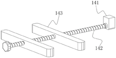
作为本技术方案的进一步改进,所述模具箱底端设置有若干限位机构,所述限位机构包括限位块,所述限位块侧面设置有丝杆,所述丝杆上螺纹连接有一对挡板,所述挡板顶端与所述模具箱底端固定连接,所述推送块底端各侧均设置有滑槽,所述滑槽与所述限位块滑动连接。As a further improvement of this technical solution, the bottom end of the mold box is provided with a number of limit mechanisms, the limit mechanism includes a limit block, the side of the limit block is provided with a screw rod, and a pair of screw rods are threadedly connected to the screw rod. A baffle, the top of the baffle is fixedly connected with the bottom end of the mold box, and each side of the bottom end of the push block is provided with a chute, and the chute is slidably connected with the limit block.
作为本技术方案的进一步改进,所述模具箱底端设置有若干底槽,所述底槽与所述滑槽保持水平一致,所述滑槽与所述限位块滑动连接。As a further improvement of the technical solution, the bottom end of the mold box is provided with a plurality of bottom grooves, the bottom grooves are kept horizontally consistent with the chute, and the chute is slidably connected to the limit block.
作为本技术方案的进一步改进,所述模具箱顶端设置有套环板,所述套环板底端与所述模具箱顶端设置连接有若干连接板。As a further improvement of the technical solution, the top end of the mold box is provided with a collar plate, and the bottom end of the collar plate and the top end of the mold box are provided with a plurality of connecting plates.
作为本技术方案的进一步改进,所述液压杆底端各侧与设置有若干固定板,所述固定板呈L型结构,所述固定板末端与所述支撑板面侧面固定连接。As a further improvement of this technical solution, each side of the bottom end of the hydraulic rod is provided with a plurality of fixing plates, the fixing plates have an L-shaped structure, and the ends of the fixing plates are fixedly connected to the side surfaces of the supporting plate surface.
作为本技术方案的进一步改进,所述连接杆底端套接有限位杆,所述限位杆与所述连接杆底端的直线距离与所述推送块顶端到套环板顶端直线距离保持一致。As a further improvement of this technical solution, the bottom end of the connecting rod is sleeved with a limiting rod, and the linear distance between the limiting rod and the bottom end of the connecting rod is consistent with the linear distance from the top of the push block to the top of the collar plate.
与现有技术相比,本实用新型的有益效果:Compared with the prior art, the beneficial effects of the present utility model:
1、该垂直推送式建筑泡沫板用定型模具中,通过设置的推送机构,具体使用时,当建筑泡沫板在其模具箱内端进行挤压成型后,通过液压杆带动连接杆向上移动,从而带动推送块向上移动,推送块将其成型后的建筑泡沫板向上垂直推出模具箱顶端,实现自动搬运,无需人工手动进行提拉,减少其操作人员工作量。1. In this vertical push-type building foam board setting mold, through the set push mechanism, when the building foam board is extruded at the inner end of the mold box, the hydraulic rod drives the connecting rod to move upward, so as to Drive the push block to move upward, and the push block pushes the formed building foam board up and vertically out of the top of the mold box to realize automatic handling without manual lifting, reducing the workload of its operators.
2、该垂直推送式建筑泡沫板用定型模具中,通过设置的复位弹簧,当需要对其成型后的建筑泡沫板进行推送时,顶端装置将会对其支杆进行施压,此时复位弹簧受到挤压收缩,同时提供一个反向作用力,以减缓其顶端装置施加的压力,从而起到建筑抗压的作用,维持整个装置的稳定性。2. In the vertical push-type building foam board setting mold, through the set return spring, when the shaped building foam board needs to be pushed, the top device will press the support rod, and the return spring It is squeezed and contracted, and at the same time, it provides a reverse force to slow down the pressure exerted by the top device, so as to play the role of building compression resistance and maintain the stability of the entire device.
附图说明Description of drawings
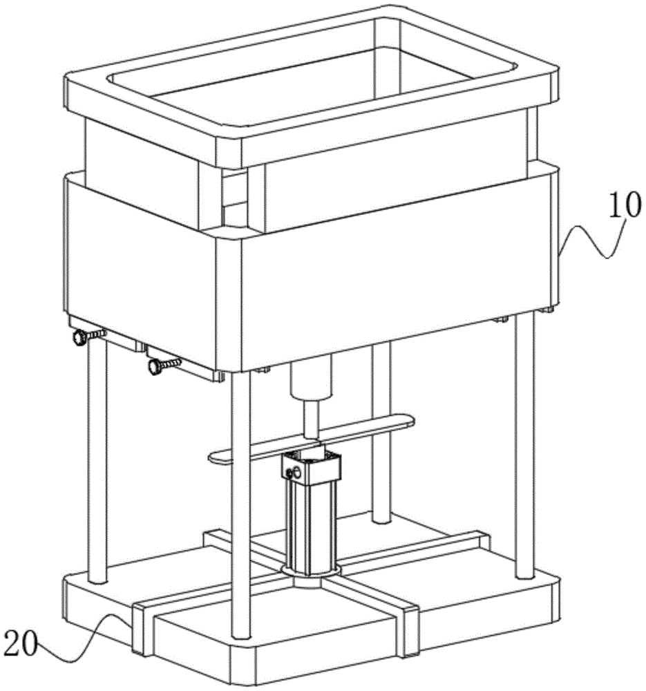
图1为本实用新型实施例1的整体结构示意图;1 is a schematic diagram of the overall structure of Embodiment 1 of the present utility model;
图2为本实用新型实施例1的模具成型机构结构拆分图;Fig. 2 is the structure disassembly diagram of the mold forming mechanism of the utility model embodiment 1;
图3为本实用新型实施例1的图2的A处局部放大图;Fig. 3 is the partial enlarged view of the A place of Fig. 2 of the utility model embodiment 1;
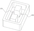
图4为本实用新型实施例1的模具箱结构示意图;4 is a schematic structural diagram of a mold box according to Embodiment 1 of the present utility model;
图5为本实用新型实施例1的限位机构结构示意图;5 is a schematic structural diagram of the limiting mechanism according to Embodiment 1 of the present invention;
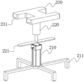
图6为本实用新型实施例1的推送机构结构示意图。FIG. 6 is a schematic structural diagram of the push mechanism according to Embodiment 1 of the present invention.
图中各个标号意义为:The meanings of the symbols in the figure are:
10、模具成型机构;110、支撑板面;120、支杆;121、插柱;122、复位弹簧;130、模具箱;131、推送槽;132、底槽;140、限位机构;141、限位块;142、丝杆;143、挡板;150、套环板;151、连接板;10. Mould forming mechanism; 110, Supporting plate surface; 120, Support rod; 121, Post; 122, Return spring; 130, Mould box; 131, Push groove; 132, Bottom groove; 140, Limiting mechanism; 141, Limit block; 142, lead screw; 143, baffle plate; 150, collar plate; 151, connecting plate;
20、推送机构;210、液压杆;211、固定板;220、连接杆;221、限位杆;230、推送块;231、滑槽。20, push mechanism; 210, hydraulic rod; 211, fixed plate; 220, connecting rod; 221, limit rod; 230, push block; 231, chute.
具体实施方式Detailed ways
下面将结合本实用新型实施例中的附图,对本实用新型实施例中的技术方案进行清楚、完整地描述,显然,所描述的实施例仅仅是本实用新型一部分实施例,而不是全部的实施例。基于本实用新型中的实施例,本领域普通技术人员在没有做出创造性劳动前提下所获得的所有其他实施例,都属于本实用新型保护的范围。The technical solutions in the embodiments of the present utility model will be clearly and completely described below with reference to the accompanying drawings in the embodiments of the present utility model. Obviously, the described embodiments are only a part of the embodiments of the present utility model, rather than all the implementations. example. Based on the embodiments of the present invention, all other embodiments obtained by those of ordinary skill in the art without creative work fall within the protection scope of the present invention.
在本实用新型的描述中,需要理解的是,术语“中心”、“纵向”、“横向”、“长度”、“宽度”、“厚度”、“上”、“下”、“前”、“后”、“左”、“右”、“竖直”、“水平”、“顶”、“底”、“内”、“外”、“顺时针”、“逆时针”等指示的方位或位置关系为基于附图所示的方位或位置关系,仅是为了便于描述本实用新型和简化描述,而不是指示或暗示所指的设备或元件必须具有特定的方位、以特定的方位构造和操作,因此不能理解为对本实用新型的限制。In the description of the present invention, it should be understood that the terms "center", "longitudinal", "lateral", "length", "width", "thickness", "upper", "lower", "front", "Back", "Left", "Right", "Vertical", "Horizontal", "Top", "Bottom", "Inner", "Outer", "Clockwise", "Counterclockwise" etc. Or the positional relationship is based on the orientation or positional relationship shown in the accompanying drawings, which is only for the convenience of describing the present invention and simplifying the description, rather than indicating or implying that the referred device or element must have a specific orientation, be constructed in a specific orientation and operation, so it cannot be construed as a limitation to the present invention.
此外,术语“第一”、“第二”仅用于描述目的,而不能理解为指示或暗示相对重要性或者隐含指明所指示的技术特征的数量。由此,限定有“第一”、“第二”的特征可以明示或者隐含地包括一个或者更多个该特征。在本实用新型的描述中,“多个”的含义是两个或两个以上,除非另有明确具体的限定。In addition, the terms "first" and "second" are only used for descriptive purposes, and should not be construed as indicating or implying relative importance or implying the number of indicated technical features. Thus, a feature defined as "first" or "second" may expressly or implicitly include one or more of that feature. In the description of the present invention, "plurality" means two or more, unless otherwise expressly and specifically defined.
实施例1Example 1
请参阅图1-图6所示,本实用新型提供一种垂直推送式建筑泡沫板用定型模具,包括模具成型机构10以及安装在模具成型机构10底端的推送机构20,模具成型机构10包括支撑板面110,支撑板面110顶端设置有若干支杆120,支杆120顶端设置有模具箱130,模具箱130内侧底端设置有推送槽131,推送机构20包括液压杆210,液压杆210底端与支撑板面110顶端固定连接,液压杆210顶端设置有连接杆220,连接杆220顶端设置有推送块230,推送块230截面尺寸与推送槽131截面尺寸保持吻合,推送块230与推送槽 131插接配合。Please refer to FIGS. 1 to 6 , the present invention provides a vertical push type mold for building foam board, including a
本实施例中,支撑板面110顶端设置有若干插槽,插槽内端插接安装有插柱121,插柱121顶端设置有复位弹簧122,复位弹簧122顶端与支杆120底端连接。具体使用时,通过设置的复位弹簧122,当需要对其成型后的建筑泡沫板进行推送时,顶端装置将会对其支杆120进行施压,此时复位弹簧122受到挤压收缩,同时提供一个反向作用力,以减缓其顶端装置施加的压力,从而起到建筑抗压的作用,维持整个装置的稳定性。In this embodiment, the top of the
进一步的,模具箱130底端设置有若干限位机构140,限位机构140包括限位块141,限位块141侧面设置有丝杆142,丝杆142上螺纹连接有一对挡板143,挡板143顶端与模具箱130底端固定连接,推送块230底端各侧均设置有滑槽231,滑槽231与限位块141 滑动连接。具体使用时,对其推送块230位置进行限定,保证推送块230完成一次推送操作后,能够重新完全卡入推送槽131内端,避免推送块230顶端突出一部分在其推送槽131 上方,导致建筑泡沫板成型型,底端将会形成凸块,导致建筑泡沫板不合格,造成资源浪费。Further, the bottom end of the
具体的,模具箱130底端设置有若干底槽132,底槽132与滑槽231保持水平一致,滑槽231与限位块141滑动连接。具体使用时,可实现对其限位块141解除限定,以保证后期能够将其推送块230滑出推送槽131底端,进行定期的保养以及润滑油的涂沫,以保证其滑动顺畅,提高其生产效率。Specifically, the bottom end of the
此外,模具箱130顶端设置有套环板150,套环板150底端与模具箱130顶端设置连接有若干连接板151。具体使用时,通过设置的套环板150,对其成型后的建筑泡沫板进行防护,避免伸出模具箱130顶端后,建筑泡沫板在其推送块230顶端出现偏移,建筑泡沫板易出现滑落,导致建筑泡沫板掉落至地面。In addition, the top end of the
除此之外,液压杆210底端各侧与设置有若干固定板211,固定板211呈L型结构,固定板211末端与支撑板面110侧面固定连接。具体使用时,通过设置的固定板211,提高液压杆210与其支撑板面110之间连接稳定性,避免在进行推送过程中,液压杆210受力不均,易出现松动,导致推送块230在其模具箱130内端出现偏移。In addition, a plurality of
具体的,连接杆220底端套接有限位杆221,限位杆221与连接杆220底端的直线距离与推送块230顶端到套环板150顶端直线距离保持一致。具体使用时,对其推送块230 向上推送的最大距离进行限定,避免推送块230升高幅度过大,导致将其建筑泡沫板完全顶出套环板150顶端,导致套环板150无法对其进行防护,同样易导致出现滑落现象。Specifically, the bottom end of the connecting
本实施例的垂直推送式建筑泡沫板用定型模具在具体使用时,首先将其建筑泡沫板原材料导入模具箱130内端,成型完成后,打开液压杆210,液压杆210带动连接杆220向上移动,连接杆220带动推送块230向上移动,推动成型后的建筑泡沫板沿着模具箱130 内端垂直向上移动,当限位杆221贴合在其模具箱130底端时,液压杆210无法继续升动,此时建筑泡沫板位于套环板150内侧,完成对其建筑泡沫板推送工作。In the specific use of the vertical push-type building foam board forming mold of this embodiment, the building foam board raw material is first introduced into the inner end of the
以上显示和描述了本实用新型的基本原理、主要特征和本实用新型的优点。本行业的技术人员应该了解,本实用新型不受上述实施例的限制,上述实施例和说明书中描述的仅为本实用新型的优选例,并不用来限制本实用新型,在不脱离本实用新型精神和范围的前提下,本实用新型还会有各种变化和改进,这些变化和改进都落入要求保护的本实用新型范围内。本实用新型要求保护范围由所附的权利要求书及其等效物界定。The basic principles, main features and advantages of the present invention are shown and described above. Those skilled in the art should understand that the present invention is not limited by the above-mentioned embodiments. The above-mentioned embodiments and descriptions are only preferred examples of the present invention and are not intended to limit the present invention. Under the premise of the spirit and scope, the present invention will have various changes and improvements, and these changes and improvements all fall within the scope of the claimed invention. The claimed scope of the present invention is defined by the appended claims and their equivalents.
Claims (7)
Priority Applications (1)
| Application Number | Priority Date | Filing Date | Title |
|---|---|---|---|
| CN202122069148.9U CN216635115U (en) | 2021-08-31 | 2021-08-31 | A vertical push type building foam board forming mold |
Applications Claiming Priority (1)
| Application Number | Priority Date | Filing Date | Title |
|---|---|---|---|
| CN202122069148.9U CN216635115U (en) | 2021-08-31 | 2021-08-31 | A vertical push type building foam board forming mold |
Publications (1)
| Publication Number | Publication Date |
|---|---|
| CN216635115U true CN216635115U (en) | 2022-05-31 |
Family
ID=81722119
Family Applications (1)
| Application Number | Title | Priority Date | Filing Date |
|---|---|---|---|
| CN202122069148.9U Active CN216635115U (en) | 2021-08-31 | 2021-08-31 | A vertical push type building foam board forming mold |
Country Status (1)
| Country | Link |
|---|---|
| CN (1) | CN216635115U (en) |
-
2021
- 2021-08-31 CN CN202122069148.9U patent/CN216635115U/en active Active
Similar Documents
| Publication | Publication Date | Title |
|---|---|---|
| CN209849633U (en) | Automobile part stamping die | |
| CN220561809U (en) | Production die for homogeneous composite insulation board | |
| CN205600936U (en) | Self preservation temperature concrete hollow block mould | |
| CN209224037U (en) | Stainless Molding Board stacks equipment | |
| CN207211747U (en) | A kind of civil engineering building template link | |
| CN105365032B (en) | A kind of hollow brick press Heng Tui end compressions mechanism | |
| CN210362174U (en) | Foam production is with foaming shaping template of convenient dismantlement | |
| CN206707274U (en) | A kind of cross beam mould shape steel form | |
| CN219621995U (en) | Insulation board for building | |
| CN209095703U (en) | A kind of pressing device for eps foam plate | |
| CN106607986A (en) | Automatic mold releasing device for foam concrete | |
| CN219095830U (en) | Shaping device for extruded sheet of steel wire mesh frame composite insulation board | |
| CN211194325U (en) | Automatic brick making machine system | |
| CN109235805B (en) | Autoclaved aerated concrete heat-insulation wallboard and production process | |
| CN211010747U (en) | A foam board that is easy to combine and splicing | |
| CN202241970U (en) | Bending-regulating device used for plastic profile production | |
| CN221392028U (en) | Truck cooling fan blade injection mold easy to assemble and replace | |
| CN216031568U (en) | Evaporate and press aerated concrete production with pouring device | |
| CN220372128U (en) | Metal material compression molding equipment | |
| CN207657111U (en) | The Double-ejection demoulding mechanism of mold | |
| CN218083262U (en) | Quick-setting asbestos fiberboard production setting device | |
| CN221193794U (en) | Polystyrene foam board convenient to combination installation | |
| CN206603658U (en) | A kind of baking box inner bag casing | |
| CN204367142U (en) | A kind of energy-saving board plate forming groove | |
| CN216397622U (en) | A processing mold with automatic blanking function |
Legal Events
| Date | Code | Title | Description |
|---|---|---|---|
| GR01 | Patent grant | ||
| GR01 | Patent grant | ||
| TR01 | Transfer of patent right | ||
| TR01 | Transfer of patent right |
Effective date of registration: 20220614 Address after: 342100 Banshi Industrial Park, Anyuan County, Ganzhou City, Jiangxi Province Patentee after: Ganzhou Shuangying New Material Technology Co.,Ltd. Address before: 523000 No. 95 Binhe Road, Nancheng street, Dongguan City, Guangdong Province Patentee before: Ji Fashun |