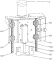
Ceramic blank rolling machine capable of effectively improving working efficiency
Technical Field
The utility model relates to a ceramic blank roller press, in particular to a ceramic blank roller press capable of effectively improving the working efficiency.
Background
The ceramic blank is formed by rolling the clay strip in a gypsum mould by a rolling head to obtain the ceramic blank. During processing, excess mud strips (i.e., waste mud) need to be discharged for disposal and recycling.
At present, the traditional ceramic blank roll forming equipment has the following technical defects: firstly, the roller press ascends and descends by rotating along a central shaft, and the roller press does not vertically ascend and descend but has radian; secondly, during rolling, the roller press is realized by pushing a push rod on an eccentric wheel and pushing the roller press by the push rod, and the roller press is complex and unstable in action and difficult to adjust.
Therefore, the traditional ceramic blank forming equipment is improved, the movement of a rolling unit is respectively completed by adopting a horizontal moving mechanism and a vertical lifting mechanism, for example, the 2-axis rail type ceramic blank internal shaping mechanism disclosed by Chinese patent document with the publication number of CN208759760U and the name of 2-axis rail type ceramic blank internal shaping mechanism comprises a plaster mold barrel, a spindle motor, a plaster mold ejector rod, a rolling machine and a mold, wherein the plaster mold barrel is rotatably erected and installed on a support mold frame, a support is installed at the top of the right end of the support mold frame, a vertical moving linear rail module used for pushing the rolling machine to move in the vertical direction is installed on the support, a transverse moving linear rail module used for pushing the rolling machine to move in the horizontal direction is also installed on the support, and the vertical moving linear rail module and the transverse moving linear rail module have the same structure and respectively comprise a first servo motor, a second servo motor and a second servo motor, Shaft coupling, motor fixing base, lead screw, fixing base, slip table and line rail module main part.
However, the applicant finds that although the technology solves the problems of the traditional ceramic blank forming equipment, the vertical moving linear rail module and the horizontal moving linear rail module both adopt a reciprocating mechanism consisting of a first servo motor and a screw rod, so that the pressure of a die head of a roller press is low, the die head is difficult to be used for ceramic blanks with large volumes, and the working efficiency is low.
Therefore, the applicant improves the technology and applies patent No. 202020746766.5 entitled "roller press capable of effectively increasing die head pressure", which comprises a frame, a plaster mold barrel driving device, a rolling device and a rolling device position double-shaft adjusting mechanism, and is characterized in that: the rolling device position double-shaft adjusting mechanism comprises a movable seat, a movable seat longitudinal moving mechanism and a rolling device vertical moving mechanism. According to the technology, the double-shaft adjusting mechanism for the position of the rolling device is improved, so that the pressure during rolling is improved, the time consumption of the rolling step can be greatly increased, the processing quality and the processing efficiency are balanced, and the requirements of a producer on the product quality and the production speed can be met.
After long-term use, the applicant finds that in the production process, the roller press waits for the vertical moving mechanism of the rolling device to drive the rolling device to descend to the right position (namely, descend into the plaster mold barrel) in each processing, so that the working efficiency of the roller press is limited by the vertical lifting speed of the rolling device, and the roller press is difficult to greatly improve.
Disclosure of Invention
The utility model aims to provide a ceramic blank roller press capable of effectively improving the working efficiency, which can greatly reduce the time consumed by vertically descending a rolling device into a plaster mold barrel and improve the working effect. The technical scheme is as follows:
the utility model provides a can effectively improve work efficiency's ceramic base rolling machine, includes frame, gypsum mould bucket drive arrangement, rolling press device position biax guiding mechanism, and rolling press device position biax guiding mechanism installs in the frame, and rolling press device installs on rolling press device position biax guiding mechanism, its characterized in that: the ceramic blank roller press further comprises a gypsum mold barrel lifting mechanism, the gypsum mold barrel lifting mechanism comprises a mounting plate and a lifting unit, the lifting unit is mounted on the frame, the mounting plate can be mounted on the frame in a vertical lifting mode, the lifting unit drives the mounting plate to lift, a gypsum mold barrel and a gypsum mold barrel driving device are mounted on the mounting plate respectively, a rotating shaft is arranged at the bottom of the gypsum mold barrel, and the gypsum mold barrel driving device is connected with the rotating shaft and drives the rotating shaft to rotate.
In an advantageous scheme, the direction of the rolling device driven by the double-shaft adjusting mechanism at the position of the rolling device is opposite to the direction of the mounting plate driven by the lifting unit. That is to say, when rolling device position biax guiding mechanism drives rolling device and descends, the lift unit drives mounting panel (gypsum mould bucket) and rises, can reduce the time that rolling device moved to in the gypsum mould bucket like this by a wide margin for ceramic base processing step's consuming time reduces, thereby improves work efficiency.
According to a better scheme, the bottom of the rack is provided with a vertical positioning plate, at least one vertical rail is arranged on the outer side surface of the vertical positioning plate, at least one first sliding block is arranged on each vertical rail respectively, and all the first sliding blocks are connected with the mounting plate respectively.
The utility model provides a scheme, the lift unit includes drive arrangement, cam, and drive arrangement has the output shaft, and drive arrangement installs in the frame, and the cam is installed on the output shaft, and the mounting panel has the pulley seat, and the pulley is installed to pulley seat rear end, pulley and cam side rolling contact.
Preferably, the driving device comprises a first servo motor and a reduction gearbox, the first servo motor and the reduction gearbox are respectively installed on the rack, and the first servo motor drives the cam to rotate through the reduction gearbox.
In another scheme, the lifting unit comprises a hydraulic cylinder, the hydraulic cylinder is installed on the installation plate, and a piston shaft of the hydraulic cylinder vertically extends downwards and is connected with the bottom end of the rack.
According to a more preferable scheme, a bottom supporting seat is installed at the bottom end of the rack, and a piston shaft of the hydraulic cylinder is connected with the bottom supporting seat.
Preferably, the rolling device position double-shaft adjusting mechanism comprises a rolling device vertical moving unit, the rolling device vertical moving unit is installed on the rack, and the rolling device vertical moving unit is connected with the rolling device and drives the rolling device to vertically lift.
Preferably, the rolling device position double-shaft adjusting mechanism further comprises a movable seat and a movable seat longitudinal moving mechanism, at least one horizontal rail extending longitudinally and horizontally is arranged on the rack, the movable seat is slidably sleeved on all the horizontal rails, the movable seat longitudinal moving mechanism is installed on the rear side of the rack, the movable seat longitudinal moving mechanism is connected with the movable seat and drives the movable seat to move along the horizontal rails, and the rolling device vertical moving mechanism is installed on the movable seat.
More preferably, the movable seat is provided with at least one vertical guide rail extending in the vertical direction on the front side surface, at least one second sliding block is arranged on each vertical guide rail, the rolling device vertical movement mechanism comprises a second servo motor, a first screw rod, a first nut and a slidable plate, the second servo motor is arranged at the top of the movable seat, two ends of the first screw rod are rotatably arranged on the movable seat, the first nut is arranged on the first screw rod, an output shaft of the second servo motor is connected with the top end of the first screw rod, the slidable plate is fixedly connected with the first nut, all the second sliding blocks are respectively connected with the slidable plate, and the rolling device is arranged on the front side surface of the slidable plate.
Compared with the prior art, the gypsum mould barrel lifting mechanism has the advantages that the lifting unit can drive the gypsum mould barrel to ascend when the rolling device is driven to descend by the rolling device position double-shaft adjusting mechanism, so that the time of the rolling device moving into the gypsum mould barrel can be greatly reduced, the time consumed by the ceramic blank processing step is reduced, and the working efficiency is greatly improved.
Drawings
FIG. 1 is a schematic block diagram of one embodiment of the present invention;
FIG. 2 is a rear perspective view of the gypsum mold bucket, gypsum mold bucket drive, and gypsum mold bucket lift mechanism of the embodiment of FIG. 1;
FIG. 3 is a schematic view of the lifting unit of FIG. 2 with the lifting unit removed;
FIG. 4 is a schematic view of FIG. 2 with another angle of the elevator unit removed;
figure 5 is a rear perspective view of a vertically movable unit of the rolling press of the embodiment of figure 1;
fig. 6 is a rear perspective view of a plaster mold bucket, a plaster mold bucket driving device, and a plaster mold bucket lifting mechanism according to another embodiment of the present invention.
Detailed Description
As shown in fig. 1 to 5, the ceramic blank roller press capable of effectively improving the working efficiency according to an embodiment of the present application includes a frame 1, a gypsum mold barrel 2, a gypsum mold barrel driving device 3, a roller press device 4, a roller press device position double-shaft adjusting mechanism 5, and a gypsum mold barrel lifting mechanism 7, wherein the roller press device position double-shaft adjusting mechanism 5 is installed on the frame 1, and the roller press device 4 is installed on the roller press device position double-shaft adjusting mechanism 5.
Gypsum mould bucket elevating system 7 includes mounting panel 701, lifting unit 702, and lifting unit 702 installs in frame 1, but mounting panel 701 installs in frame 1 with vertical lift, and lifting unit 702 drives mounting panel 701 and goes up and down, and gypsum mould bucket 2, gypsum mould bucket drive arrangement 3 install respectively on mounting panel 701, and 2 bottoms of gypsum mould bucket have pivot 201, and gypsum mould bucket drive arrangement 3 adopts belt pulley drive 6 to be connected with pivot 201 and drives pivot 201 and rotate.
The rolling device 4 is driven by the rolling device position double-shaft adjusting mechanism 5 to move in a direction opposite to the direction in which the mounting plate 701 is driven by the lifting unit 702 to move. That is to say, when the rolling device position double-shaft adjusting mechanism 5 drives the rolling device 4 to descend, the lifting unit 702 drives the mounting plate 701 to ascend, so that the time for the rolling device 4 to move into the gypsum mold barrel 2 can be greatly reduced, the time consumed by the ceramic blank processing step is reduced, and the working efficiency is improved.
In an alternative embodiment, the bottom of the frame 1 is provided with a vertical positioning plate 101, two vertical rails 102 are mounted on the outer side of the vertical positioning plate 101, two first sliding blocks 103 are respectively mounted on each vertical rail 102, and all the first sliding blocks 103 are respectively connected with the mounting plate 701.
In an alternative embodiment, the lifting unit 702 includes a driving device 7021 and a cam 7022, the driving device 7021 has an output shaft 70211, the driving device 7021 is mounted on the frame 1, the cam 7022 is mounted on the output shaft 70211, the mounting plate 701 has a pulley seat 7011, a pulley 7012 is mounted at the rear end of the pulley seat 7011, and the pulley 7012 is in rolling contact with the side edge of the cam 7022.
The driving device 7021 comprises a first servo motor 70213 and a reduction gearbox 70212 (an output shaft 70211 is connected with the reduction gearbox 70212), the first servo motor 70213 and the reduction gearbox 70212 are respectively installed on the rack 1, and the first servo motor 70213 drives the cam 7022 to rotate through the reduction gearbox 70212.
As shown in fig. 6, in another alternative embodiment, the lifting unit 702 comprises a hydraulic cylinder 7023, the hydraulic cylinder 7023 is mounted on the mounting plate 701, and a piston shaft 70231 of the hydraulic cylinder 7023 extends vertically downward and is connected to the bottom end of the machine frame 1.
The bottom end of the machine frame 1 is provided with a bottom supporting seat 105, and a piston shaft 70231 of a hydraulic cylinder 7023 is connected with the bottom supporting seat 105.
The rack 1 is provided with two horizontal rails 104 extending longitudinally and horizontally, the rolling device position double-shaft adjusting mechanism 5 comprises a movable seat 501, a movable seat longitudinal moving mechanism 502 and a rolling device vertical moving mechanism 503, the movable seat 501 is slidably sleeved on the two horizontal rails 104, the movable seat longitudinal moving mechanism 502 is installed on the rear side of the rack 1, the movable seat longitudinal moving mechanism 502 is connected with the movable seat 501 and drives the movable seat 501 to move along the horizontal rails 104, the rolling device vertical moving mechanism 503 is installed on the movable seat 501, and the rolling device vertical moving mechanism 503 is connected with the rolling device 4 and drives the rolling device 4 to vertically lift.
Two vertical guide rails 5012 extending in the vertical direction are installed on the front side surface of the movable base 501, and the rolling device 4 is slidably installed on the front side surface of the movable base 501 along the vertical guide rails 5012. Two second slide blocks 5011 are respectively mounted on each vertical guide rail 5012.
The vertical moving mechanism 503 of the rolling device includes a second servo motor 5031, a first lead screw 5032, a first nut 5033 and a slidable plate 5034, the second servo motor 5031 is installed on the top of the movable seat 501, two ends of the first lead screw 5032 are rotatably installed on the movable seat 501, the first nut 5033 is installed on the first lead screw 5032, an output shaft of the second servo motor 5031 is connected to the top end of the first lead screw 5032, the slidable plate 5034 is fixedly connected to the first nut 5033, and all the second sliding blocks 5011 are respectively connected to the slidable plate 5034, and the rolling device 4 is installed on the front side surface of the slidable plate 5034.
The following operation is described with reference to fig. 1-6:
the control device of the ceramic blank rolling machine (in this embodiment, a PLC control device) controls the second servo motor 5031 and the first servo motor 70213 (or the hydraulic cylinder 7023) to operate respectively, so that the rolling device position double-shaft adjusting mechanism 5 drives the rolling device 4 to descend, and meanwhile, the lifting unit 702 drives the gypsum mold barrel 2 to ascend, thereby greatly reducing the time for the rolling device 4 to move into the gypsum mold barrel 2, reducing the time consumed by the ceramic blank processing step, and improving the work efficiency.
After the processing is finished, the control device of the ceramic blank rolling machine controls the second servo motor 5031 to rotate reversely and the first servo motor 70213 to rotate reversely (or the piston shaft of the hydraulic cylinder 7023 contracts), so that the rolling device position double-shaft adjusting mechanism 5 drives the rolling device 4 to ascend to the original position, and at the same time, the lifting unit 702 drives the gypsum mold barrel 2 to descend to the original position.
In addition, it should be noted that the names of the parts and the like of the embodiments described in the present specification may be different, and the equivalent or simple change of the structure, the characteristics and the principle described in the present patent idea is included in the protection scope of the present patent. Various modifications, additions and substitutions for the specific embodiments described may be made by those skilled in the art without departing from the scope of the utility model as defined in the accompanying claims.