CN216631502U - Suspension type linear material sieving device - Google Patents
Suspension type linear material sieving device Download PDFInfo
- Publication number
- CN216631502U CN216631502U CN202122553393.7U CN202122553393U CN216631502U CN 216631502 U CN216631502 U CN 216631502U CN 202122553393 U CN202122553393 U CN 202122553393U CN 216631502 U CN216631502 U CN 216631502U
- Authority
- CN
- China
- Prior art keywords
- screen
- frame
- screen body
- elastic
- connecting rod
- Prior art date
- Legal status (The legal status is an assumption and is not a legal conclusion. Google has not performed a legal analysis and makes no representation as to the accuracy of the status listed.)
- Active
Links
Images



Classifications
-
- Y—GENERAL TAGGING OF NEW TECHNOLOGICAL DEVELOPMENTS; GENERAL TAGGING OF CROSS-SECTIONAL TECHNOLOGIES SPANNING OVER SEVERAL SECTIONS OF THE IPC; TECHNICAL SUBJECTS COVERED BY FORMER USPC CROSS-REFERENCE ART COLLECTIONS [XRACs] AND DIGESTS
- Y02—TECHNOLOGIES OR APPLICATIONS FOR MITIGATION OR ADAPTATION AGAINST CLIMATE CHANGE
- Y02W—CLIMATE CHANGE MITIGATION TECHNOLOGIES RELATED TO WASTEWATER TREATMENT OR WASTE MANAGEMENT
- Y02W30/00—Technologies for solid waste management
- Y02W30/50—Reuse, recycling or recovery technologies
- Y02W30/52—Mechanical processing of waste for the recovery of materials, e.g. crushing, shredding, separation or disassembly
Landscapes
- Combined Means For Separation Of Solids (AREA)
Abstract
The utility model relates to a suspension type linear material sieving device, and belongs to the technical field of sieving equipment. The device comprises a screen body (1) and a frame (10), wherein the screen body (1) is of a funnel-shaped structure, the frame (10) is arranged at the opening of the large end of the screen body (1), a vibrating motor (4) is arranged on the outer wall of the screen body (1), a screen mesh (8) is arranged at the opening of the large end of the screen body (1), the screen mesh (8) is detachably connected with the frame (10), and a plurality of elastic hanging pieces are uniformly arranged on the frame (10). This device hangs fixedly screen frame (1) through elasticity piece of hanging for this device is according to different places adjustment mounting height and screen frame inclination, and easy maintenance operation is reliable simultaneously, and vibration noise is low, and long service life has improved work efficiency. The problem of current console mode screening equipment occupation space big, screening inclination is adjusted inconveniently, cleans inconveniently after the screening is solved.
Description
Technical Field
The utility model relates to a suspension type linear material sieving device, and belongs to the technical field of sieving equipment.
Background
The development of screening machines began in the middle of this century. The development process of domestic vibration screening equipment goes through three stages, namely a simulation stage, a self-development stage and an improvement stage. With the recent rapid development of the mechanical industry, domestic enterprises pay more and more attention to the research on the material screening device technology, and continuously conduct independent research, development and innovation, and at the same time, introduce newer technology from abroad. The technical difference between the domestic material sieving device and the foreign material sieving device is smaller and smaller, and part of products reach the international advanced level.
The installation that current large-scale screening equipment mainly adopted the support to fix and realize equipment on the holding surface, and screen cloth and screen frame are connected fixedly, lead to its screening angle can only realize adjusting through the mounted position, in case be difficult for adjusting its screening angle once more after the installation is accomplished. Meanwhile, the screening equipment needs to be cleaned actually due to the phenomena of material leakage, ash falling and the like after being used every time, and the fixedly installed screening equipment occupies a large space and is inconvenient to clean.
SUMMERY OF THE UTILITY MODEL
The utility model aims to solve the technical problems that the existing floor type screening equipment occupies large space, the screening inclination angle is inconvenient to adjust, and the cleaning is inconvenient after screening.
The technical scheme adopted by the utility model for solving the technical problem is as follows: suspension type sharp sieve glassware, including screen frame and frame, the screen frame is funnel-shaped structure, and the frame setting is provided with vibrating motor on the screen frame outer wall at screen frame main aspects opening part, and screen frame main aspects opening part is provided with the screen cloth, and the screen cloth can be dismantled with the frame and be connected, evenly is provided with a plurality of elasticity on the frame and hangs the piece.
The elastic hanging piece in the device comprises a lifting lug and an elastic piece, the lifting lug is arranged on the frame, and one end of the elastic piece is connected with the lifting lug.
Further, in the device, the elastic part comprises a suspender, an elastic sleeve, a spring and a connecting rod, the elastic sleeve is of a tubular structure with one end sealed, the sealed end is connected with one end of the suspender, one end of the connecting rod extends into the elastic sleeve, the extending end is provided with a fixed block, the open end of the elastic sleeve is provided with a plugging plate with a through hole, the other end of the connecting rod penetrates through the plugging plate to be connected with the lifting lug, the spring sleeve is arranged on the connecting rod, and two ends of the spring sleeve are respectively in contact connection with the fixed block and the plugging plate on the opposite sides.
Wherein, among the above-mentioned device the big end opening of screen frame is the rectangle structure, and the frame is hollow rectangle structure, and the lower hopper eccentric settings of screen frame is in the one end of screen frame, and the screen cloth setting is directly over the hopper down.
Wherein, the screen frame is provided with the unloading baffle by the connection terminal surface department of screen cloth side among the above-mentioned device, the unloading baffle is the U-shaped structure, and sets up the striker plate on the both sides wall.
The device is characterized in that mounting bulges are arranged on the side wall of the screen body and are arranged at intervals along the width direction of the screen body, the discharging hopper is positioned in the middle of the mounting bulges and is staggered, and the vibration motor is arranged at the end parts of the mounting bulges.
The beneficial effects of the utility model are: this device simple structure, the preparation is convenient, and this device hangs the screen frame fixedly through elasticity piece for this device is according to different places adjustment mounting height and screen frame inclination, and easy maintenance operation is reliable simultaneously, and the vibration noise is low, and long service life has improved work efficiency. The device has the advantages of small volume, light weight, convenient installation and adjustment, large screening capacity, convenient maintenance and reliable operation, low vibration noise, long service life and improvement on working efficiency, and can adjust the installation height and the inclination angle of the screen body according to different places. Simultaneously can select for use the screen cloth in suitable aperture according to the screening material demand of difference, through vibrating motor transmission, sieve material ware linear motion realizes the material screening to guarantee authenticity, security, the reliability that suspension type linear sieve material ware used.
Drawings
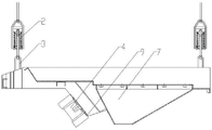
FIG. 1 is a schematic view of the structure of the present invention;
FIG. 2 is an enlarged view of the structure at I in FIG. 1 according to the present invention;
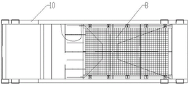
FIG. 3 is a schematic top view of the present invention;
FIG. 4 is a schematic view of a full-section structure of the present invention;
FIG. 5 is a schematic view of the end face of the screen body near the end of the screen mesh;
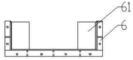
fig. 6 is a schematic view of the blanking baffle structure of the utility model.
Reference numerals are as follows: 1 is the screen frame, 2 is the elastic component, 21 is the jib, 22 is the elastic sleeve, 23 is the spring, 24 is the shutoff board, 25 is the connecting rod, 26 is the fixed block, 3 is the lug, 4 is vibrating motor, 5 is the connection terminal surface, 6 is the unloading baffle, 61 is the striker plate, 7 is the hopper, 8 is the screen cloth, 9 is the installation arch, 10 is the frame.
Detailed Description
The utility model is further described below with reference to the accompanying drawings.
As shown in fig. 1 to 6, the suspension type linear material screening device of the present invention includes a screen body 1 and a frame 10, wherein the screen body 1 is of a funnel-shaped structure, the frame 10 is disposed at an opening of a large end of the screen body 1, a vibration motor 4 is disposed on an outer wall of the screen body 1, a screen 8 is disposed at the opening of the large end of the screen body 1, the screen 8 is detachably connected with the frame 10, and a plurality of elastic hanging members are uniformly disposed on the frame 10. As can be understood by those skilled in the art, the screen body 1 is preferably of a funnel-shaped structure, and the screen body 1 is made of stainless steel and is actually welded directly with the frame 10 to form a main body. Vibrating motor 4 makes whole screen frame 1 vibrate to make screen cloth 8 reduce the phenomenon that the material blockked up the sieve mesh, make screen cloth 8 have higher screening efficiency and productivity ratio, screen cloth 8 passes through bolt-up with frame 10 and is connected, and screen cloth 8 can choose for use the screen cloth 8 in suitable aperture according to the screening material demand, and screen cloth 8 changes conveniently. And a plurality of elastic hanging pieces are uniformly arranged on the frame 10, the upper ends of the elastic hanging pieces are directly connected with the supporting beam or the top surface, the purpose of adjusting the screening inclination angle of the screen 8 is realized by changing the length of the elastic hanging pieces, and meanwhile, the arrangement of the elastic hanging pieces is realized.
Preferably, the elastic hanging element in the above device comprises a lifting lug 3 and an elastic element 2, the lifting lug 3 is arranged on the frame 10, and one end of the elastic element 2 is connected with the lifting lug 3. It can be understood by those skilled in the art that the device preferably comprises lifting lugs 3 and elastic members 2, wherein the lifting lugs 3 are welded at four corners of the frame 10, one end of the elastic member 2 is hung on the lifting lugs 3, and the other end of the elastic member is directly connected with a top surface or a supporting beam.
Preferably, in the above device, the elastic member 2 includes a suspension rod 21, an elastic sleeve 22, a spring 23 and a connecting rod 25, the elastic sleeve 22 is a tubular structure with one end sealed, and the sealed end is connected with one end of the suspension rod 21, one end of the connecting rod 25 extends into the elastic sleeve 22, and the extended end is provided with a fixed block 26, the open end of the elastic sleeve 22 is provided with a blocking plate 24 with a through hole, the other end of the connecting rod 25 passes through the blocking plate 24 to be connected with the lifting lug 3, the spring 23 is sleeved on the connecting rod 25, and the two ends are respectively in contact connection with the fixed block 26 and the blocking plate 24 just to the sides. It will be appreciated by those skilled in the art that the present device is only a specific configuration of the resilient member 2 that is further preferred. The elastic element 2 comprises a suspension rod 21, an elastic sleeve 22, a spring 23 and a connecting rod 25, wherein the elastic sleeve 22 is preferably a tubular structure with one end sealed, the sealed end is connected with one end of the suspension rod 21, and the other end of the suspension rod 21 is directly connected with the top surface or a supporting beam. One end of the connecting rod 25 extends into the elastic sleeve 22, the extending end is provided with a fixing block 26, the open end of the elastic sleeve 22 is provided with a blocking plate 24 with a through hole, and preferably, the blocking plate 24 is detachably connected with the elastic sleeve 22, and preferably, the threaded connection is adopted. The other end of the connecting rod 25 penetrates through the blocking plate 24 to be connected with the lifting lug 3, the spring 23 is sleeved on the connecting rod 25, and the two ends of the spring are respectively in contact connection with the opposite sides of the fixing block 26 and the blocking plate 24. The size of the fixing block 26 should be larger than the cross section of the spring 23, and the through hole of the blocking plate 24 should be smaller than the cross section of the spring 23.
Preferably, in the above device, the opening of the large end of the screen body 1 is a rectangular structure, the frame 10 is a hollow rectangular structure, the lower hopper 7 of the screen body 1 is eccentrically arranged at one end of the screen body 1, and the screen 8 is arranged right above the lower hopper 7. It can be understood by those skilled in the art that the device preferably has the shape of the large end opening of the screen body 1 and the frame 10, and further defines the position of the lower hopper 7 at the lower end of the screen body 1, and preferably the lower hopper 7 is welded with the screen body 1 so that the screen body 1 is in a funnel-shaped structure, and the lower hopper 7 is positioned below the screen mesh 8 and is used for guiding qualified materials screened by the screen mesh 8.
Preferably, the connection end face 5 of the screen frame 1 close to the screen 8 side in the device is provided with a blanking baffle 6, the blanking baffle 6 is of a U-shaped structure, and two side walls are provided with striker plates 61. As can be understood by those skilled in the art, it is preferable that a blanking baffle 6 is disposed at the connecting end face 5, which can further limit that the connecting end face 5 and the blanking baffle 6 are connected by a screw, a sealing rubber gasket is required in the middle, and the blanking baffle 6 is used for leading out unqualified materials which are not screened by the screen mesh 8. In order to prevent the material from leaking, the two U-shaped side walls of the blanking baffle 6 are preferably provided with striker plates 61.
Preferably, in the above device, the side wall of the screen body 1 is provided with mounting protrusions 9, the mounting protrusions 9 are arranged at intervals along the width direction of the screen body 1, the discharging hopper 7 is located in the middle of the mounting protrusions 9 and is arranged in a staggered manner, and the vibration motor 4 is arranged at the end of the mounting protrusions 9. As can be understood by those skilled in the art, there are preferably two vibration motors 4, and for convenience of installation, it is preferable that the side wall of the screen body 1 is provided with a mounting protrusion 9, and the vibration motors 4 are arranged at the end of the mounting protrusion 9 and directly connected by bolts. The phenomenon that the screen holes are blocked by materials is reduced through the vibrating motor 4, so that the screen 8 has higher screening efficiency and productivity. And further preferably, the mounting protrusions 9 are arranged at intervals along the width direction of the screen body 1, and the lower hopper 7 is positioned in the middle of the mounting protrusions 9 and is staggered in the length direction of the screen body 1.
Claims (6)
Priority Applications (1)
| Application Number | Priority Date | Filing Date | Title |
|---|---|---|---|
| CN202122553393.7U CN216631502U (en) | 2021-10-22 | 2021-10-22 | Suspension type linear material sieving device |
Applications Claiming Priority (1)
| Application Number | Priority Date | Filing Date | Title |
|---|---|---|---|
| CN202122553393.7U CN216631502U (en) | 2021-10-22 | 2021-10-22 | Suspension type linear material sieving device |
Publications (1)
| Publication Number | Publication Date |
|---|---|
| CN216631502U true CN216631502U (en) | 2022-05-31 |
Family
ID=81730044
Family Applications (1)
| Application Number | Title | Priority Date | Filing Date |
|---|---|---|---|
| CN202122553393.7U Active CN216631502U (en) | 2021-10-22 | 2021-10-22 | Suspension type linear material sieving device |
Country Status (1)
| Country | Link |
|---|---|
| CN (1) | CN216631502U (en) |
Cited By (1)
| Publication number | Priority date | Publication date | Assignee | Title |
|---|---|---|---|---|
| CN115518871A (en) * | 2022-11-09 | 2022-12-27 | 宁德师范学院 | A tea processing device with material separation and screening function |
-
2021
- 2021-10-22 CN CN202122553393.7U patent/CN216631502U/en active Active
Cited By (1)
| Publication number | Priority date | Publication date | Assignee | Title |
|---|---|---|---|---|
| CN115518871A (en) * | 2022-11-09 | 2022-12-27 | 宁德师范学院 | A tea processing device with material separation and screening function |
Similar Documents
| Publication | Publication Date | Title |
|---|---|---|
| CN208743009U (en) | A kind of multiple exit vibrating screen | |
| CN216800602U (en) | Vibrating filter equipment of waterborne environmental protection coating processing usefulness | |
| CN211275430U (en) | A vibrating screen for easy screen replacement | |
| CN203484338U (en) | Vibration screen bed | |
| CN219616033U (en) | Vibrating screen structure of an environmentally friendly foam raw material granulator | |
| CN111760683A (en) | Cage type cathode hanging device | |
| CN215964752U (en) | Fine chemical raw material classified screening device | |
| CN217699565U (en) | Cement manufacture raw materials deironing device | |
| CN216105521U (en) | Adjustable building material lifting device | |
| CN214235024U (en) | Half-diamond anti-blocking screen | |
| CN211330224U (en) | Environment-friendly material screening device for garden building construction site | |
| CN209871748U (en) | Blocking-proof device for producing wollastonite | |
| CN213194495U (en) | Powder coating vibrating screen | |
| CN218502624U (en) | Uniform filtering device for vitrified micro bubble expansion process | |
| CN218655451U (en) | Sand screening device | |
| CN222919090U (en) | A vibrating screen for refractory material production | |
| CN223417703U (en) | A vibrating screen for feeding port of feed mixing bin | |
| CN224072601U (en) | Cement fineness screening installation | |
| CN221017364U (en) | Vibrating screen with cleaning mechanism | |
| CN212120810U (en) | Shale shaker for ore dressing | |
| CN206454403U (en) | A kind of dust arrester | |
| CN211303770U (en) | A leaf spring screen | |
| CN216800564U (en) | Building material filter equipment | |
| CN223996617U (en) | Novel carbamate sieve plate | |
| CN222919035U (en) | Multistage screening plant of aggregate preparation |
Legal Events
| Date | Code | Title | Description |
|---|---|---|---|
| GR01 | Patent grant | ||
| GR01 | Patent grant |