CN216630245U - Waste gas treatment equipment - Google Patents
Waste gas treatment equipment Download PDFInfo
- Publication number
- CN216630245U CN216630245U CN202123409586.1U CN202123409586U CN216630245U CN 216630245 U CN216630245 U CN 216630245U CN 202123409586 U CN202123409586 U CN 202123409586U CN 216630245 U CN216630245 U CN 216630245U
- Authority
- CN
- China
- Prior art keywords
- box
- electrode
- box body
- gas treatment
- side board
- Prior art date
- Legal status (The legal status is an assumption and is not a legal conclusion. Google has not performed a legal analysis and makes no representation as to the accuracy of the status listed.)
- Active
Links
- 239000002912 waste gas Substances 0.000 title abstract description 26
- OKTJSMMVPCPJKN-UHFFFAOYSA-N Carbon Chemical compound [C] OKTJSMMVPCPJKN-UHFFFAOYSA-N 0.000 claims abstract description 37
- 238000000746 purification Methods 0.000 claims abstract description 33
- 238000007599 discharging Methods 0.000 claims description 6
- 230000004308 accommodation Effects 0.000 claims description 4
- 239000007789 gas Substances 0.000 description 13
- 231100000331 toxic Toxicity 0.000 description 6
- 230000002588 toxic effect Effects 0.000 description 6
- 229910052799 carbon Inorganic materials 0.000 description 5
- 239000000428 dust Substances 0.000 description 4
- 230000000694 effects Effects 0.000 description 4
- 238000000034 method Methods 0.000 description 4
- 239000002245 particle Substances 0.000 description 4
- 239000000463 material Substances 0.000 description 3
- 239000010815 organic waste Substances 0.000 description 3
- 230000000903 blocking effect Effects 0.000 description 2
- 239000003153 chemical reaction reagent Substances 0.000 description 2
- 230000007547 defect Effects 0.000 description 2
- 230000005684 electric field Effects 0.000 description 2
- 238000006056 electrooxidation reaction Methods 0.000 description 2
- 238000012986 modification Methods 0.000 description 2
- 230000004048 modification Effects 0.000 description 2
- 230000002035 prolonged effect Effects 0.000 description 2
- 238000006722 reduction reaction Methods 0.000 description 2
- 238000006467 substitution reaction Methods 0.000 description 2
- 206010019233 Headaches Diseases 0.000 description 1
- 238000004887 air purification Methods 0.000 description 1
- 231100000869 headache Toxicity 0.000 description 1
- 230000007774 longterm Effects 0.000 description 1
- 230000002085 persistent effect Effects 0.000 description 1
- 231100000614 poison Toxicity 0.000 description 1
- 230000007096 poisonous effect Effects 0.000 description 1
- 239000007921 spray Substances 0.000 description 1
- 238000005507 spraying Methods 0.000 description 1
Images



Classifications
-
- Y—GENERAL TAGGING OF NEW TECHNOLOGICAL DEVELOPMENTS; GENERAL TAGGING OF CROSS-SECTIONAL TECHNOLOGIES SPANNING OVER SEVERAL SECTIONS OF THE IPC; TECHNICAL SUBJECTS COVERED BY FORMER USPC CROSS-REFERENCE ART COLLECTIONS [XRACs] AND DIGESTS
- Y02—TECHNOLOGIES OR APPLICATIONS FOR MITIGATION OR ADAPTATION AGAINST CLIMATE CHANGE
- Y02A—TECHNOLOGIES FOR ADAPTATION TO CLIMATE CHANGE
- Y02A50/00—TECHNOLOGIES FOR ADAPTATION TO CLIMATE CHANGE in human health protection, e.g. against extreme weather
- Y02A50/20—Air quality improvement or preservation, e.g. vehicle emission control or emission reduction by using catalytic converters
Landscapes
- Treating Waste Gases (AREA)
Abstract
The utility model provides a waste gas treatment device in the technical field of waste gas treatment, which comprises a box body with a containing cavity, wherein one end of the box body is provided with an air inlet pipe, the other end of the box body is provided with an air outlet pipe, a support frame is detachably connected in the box body close to the air inlet pipe, a filter screen is arranged on the support frame, two groups of electrode purification units are arranged in the box body between the filter screen and the air outlet pipe, each electrode purification unit comprises an anode electrode and a cathode electrode, air holes are respectively arranged on the anode electrode and the cathode electrode, a plurality of activated carbon are filled between the anode electrode and the cathode electrode, a choke unit is arranged between the two groups of electrode purification units, the choke unit comprises a left side plate and a right side plate which are arranged at intervals, the left side plate is close to the air inlet pipe, the right side plate is close to the air outlet pipe, the upper side of the left side plate is fixed at the upper end of the box body, a left channel is reserved between the left side plate and the lower side of the box body is fixed at the lower end of the box body, a right channel is reserved between the right side plate and the upper side of the box body; the utility model has convenient use and high purification efficiency.
Description
Technical Field
The utility model belongs to the technical field of waste gas treatment, and particularly relates to waste gas treatment equipment.
Background
Along with the development of economy, people pay more and more attention to the surrounding environment, most of domestic garbage in vast rural areas and cities is buried, the garbage is not reduced and recycled, serious secondary pollution is very persistent, the garbage treatment is a headache problem in large cities with dense population, and the garbage is collected and then sent to a garbage transfer station, and is subjected to specific treatment in the garbage transfer station and then sent to a next-stage treatment unit for treatment.
In the prior art, the garbage transfer station has great peculiar smell, the peculiar smell remains in the air, the waste gas treatment method generally set up at the garbage transfer station is various, for example, the spraying method is to spray chemical reagent, carry out chemisorption, recycle activated carbon or other microporous adsorbing materials, the air flows through the adsorbing material and adsorbs poisonous or harmful organic waste gas on the adsorbing material to reach the air purification effect, but the treatment effect of the method is not ideal, the sprayed chemical reagent needs to be collected again for treatment, and the chemisorption easily causes secondary pollution, and the use is inconvenient.
SUMMERY OF THE UTILITY MODEL
Aiming at the defects in the prior art, the utility model aims to solve the defects in the prior art, solve the technical problems of inconvenient use and low purification efficiency in the prior art, and provide the waste gas treatment equipment.
The purpose of the utility model is realized by the following steps: a waste gas treatment device comprises a box body with a containing cavity, wherein an air inlet pipe is arranged at one end of the box body, an air outlet pipe is arranged at the other end of the box body, a support frame is detachably connected in the box body and is close to the air inlet pipe, a filter screen is arranged on the support frame, two groups of electrode purification units are arranged in the box body between the filter screen and the air outlet pipe, each electrode purification unit comprises a positive electrode and a negative electrode, air holes are respectively formed in the positive electrode and the negative electrode, a plurality of activated carbon is filled between the positive electrode and the negative electrode, a choke unit is arranged between the two groups of electrode purification units and comprises a left side plate and a right side plate which are arranged at intervals, the left side plate is close to the air inlet pipe, the right side plate is close to the air outlet pipe, the upper side of the left side plate is fixed at the upper end of the box body, a left channel is reserved between the left side plate and the lower side of the box body, and the lower side of the right side plate is fixed at the lower end of the box body, a right channel is left between the right side plate and the upper side of the box body.
In the utility model, the waste gas flows into the box body from the air inlet pipe of the box body, the waste gas firstly passes through the filter screen, the filter screen filters large particle dust in the waste gas, then the waste gas continuously flows through an electrode purification unit, the waste gas with the large particle dust removed flows into the electrode purification unit from the air holes of the anode electrode, the anode electrode is positively charged, the cathode electrode is negatively charged, the activated carbon is acted by the electric fields of the anode electrode and the cathode electrode, each activated carbon is converted into an independent electrode, organic components in the toxic and harmful organic waste gas are firstly adsorbed by the activated carbon, then electrochemical oxidation and reduction reactions are simultaneously carried out on the surface of the activated carbon to decompose the organic components, the toxic and harmful organic waste gas adsorbed by the activated carbon is removed, the waste gas flows out to the wind resistance unit from the air holes on the cathode electrode, and the time for the waste gas to stay in the electrode purification unit is prolonged under the action of the wind resistance unit, the waste gas flowing out of the air holes sequentially enters the next electrode purification unit from the left channel and the right channel for secondary purification, and the air after secondary purification is discharged to the next-stage treatment unit from an air outlet pipe of the box body; the electrode purification unit is arranged to remove toxic and harmful gases in the waste gas, so that secondary pollution is avoided, and the treatment effect is good; the arrangement of the choke unit prolongs the time for the waste gas to stay in the electrode purification unit, and the purification efficiency is high; the method can be applied to the treatment work of the waste gas.
In order to conveniently change the activated carbon, a screen frame is arranged between the anode electrode and the cathode electrode, the upper side and the lower side of the screen frame are attached to the inner wall of the box body, the front side and the rear side of the screen frame are attached to the inner wall of the box body, the screen frame is provided with a containing space, a plurality of activated carbon is filled in the containing space, the upper end and the lower end of the screen frame are respectively provided with an upper opening and a lower opening which are communicated with the containing space, a feeding pipe communicated with the upper opening is arranged on the box body right above the screen frame, and a discharging pipe communicated with the lower opening is arranged on the box body right below the screen frame.
In order to facilitate the opening and closing of the feeding pipe and the discharging pipe, the upper end of the feeding pipe is connected with an upper cover plate through a bolt, and the outward end of the discharging pipe is connected with a lower cover plate through a bolt.
In order to supply power to the anode electrode and the cathode motor, an anode wire socket extending out of the box body is arranged on the anode electrode, and a cathode wire socket extending out of the box body is arranged on the cathode electrode.
In order to realize being connected with dismantling of filter screen and box, the symmetry is equipped with slide rail and lower slide rail in the box, goes up the slide rail and is the same with lower slide rail structure, the upper end of support frame can slide along last slide rail, and the lower extreme of support frame can slide along lower slide rail, still be equipped with the retaining member on the support frame, be equipped with the locking hole on the retaining member, still be equipped with in the box with the screw hole of axle center with the locking hole, the support frame can be in the box through retaining member locking.
In order to conveniently clean or replace the filter screen, a switch door is hinged to the box body close to the filter screen, and a door lock is arranged on the switch door.
Drawings
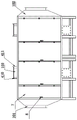
Fig. 1 is a front view of the present invention.
Fig. 2 is a schematic view of the opening/closing door of the present invention in an opened state.
Fig. 3 is a partially enlarged view of a portion a in fig. 2.
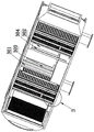
Fig. 4 is a schematic view of the internal structure of the present invention.
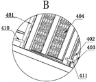
Fig. 5 is a partially enlarged view of B in fig. 4.
Fig. 6 is a schematic structural view of the screen frame of the present invention.
In the figure: 1 box, 101 air-supply line, 102 play tuber pipe, 103 inlet pipes, 104 discharging pipe, 2 the support frame, 201 the filter screen, 3 the unit of hindering the wind, 301 left side board, 302 right side board, 303 left side passageway, 304 right side passageway, 4 electrode purification unit, 401 positive pole, 402 negative pole, 403 bleeder vent, 404 screen frame, 405 accommodation space, 406 upper shed, 407 lower open-ended, 408 upper cover plate, 409 lower cover plate, 410 positive pole electric wire socket, 411 negative pole electric wire socket, 5 lower slide rail, 6 retaining member, 601 locking hole, 7 switch doors, 8 locks.
Detailed Description
The utility model will be further described with reference to the accompanying drawings.
As shown in fig. 1 to 6, the waste gas treatment equipment comprises a box body 1 with a containing cavity, one end of the box body 1 is provided with an air inlet pipe 101, the other end of the box body 1 is provided with an air outlet pipe 102, a support frame 2 is detachably connected in the box body 1 close to the air inlet pipe 101, the support frame 2 is provided with a filter screen 201, an upper slide rail and a lower slide rail 5 are symmetrically arranged in the box body 1, the upper slide rail and the lower slide rail 5 have the same structure, the upper end of the support frame 2 can slide along the upper slide rail, the lower end of the support frame 2 can slide along the lower slide rail 5, the support frame 2 is also provided with a locking part 6, the locking part 6 is provided with a locking hole 601, a switch door 7 is hinged on the box body 1 close to the filter screen 201, and the switch door 7 is provided with a door lock 8; a threaded hole coaxial with the locking hole 601 is also formed in the box body 1, and the support frame 2 can be locked in the box body 1 through a locking piece 6; two groups of electrode purification units 4 are arranged in the box body 1 between the filter screen 201 and the air outlet pipe 102, each electrode purification unit 4 comprises an anode electrode 401 and a cathode electrode 402, an anode wire socket 410 extending out of the box body 1 is arranged on the anode electrode 401, a cathode wire socket 411 extending out of the box body is arranged on the cathode electrode 402, air vents 403 are respectively arranged on the anode electrode 401 and the cathode electrode 402, a plurality of activated carbons are filled between the anode electrode 401 and the cathode electrode 402, a screen frame 404 is arranged between the anode electrode 401 and the cathode electrode 402, the upper side and the lower side of the screen frame 404 are attached to the inner wall of the box body 1, the front side and the rear side of the screen frame 404 are attached to the inner wall of the box body 1, the screen frame 404 is provided with a containing space 405, the plurality of activated carbons are filled in the containing space 405, the upper end and the lower end of the screen frame 404 are respectively provided with an upper opening 406 and a lower opening 407 communicated with the containing space 405, a feeding pipe 103 communicated with the upper opening 406 is arranged on the box body 1 right above the screen frame 404, a discharge pipe 104 communicated with the lower opening 407 is arranged on the box body 1 right below the screen frame 404, the upper end of the feed pipe 103 is connected with an upper cover plate 408 through a bolt, and the outward end of the discharge pipe 104 is connected with a lower cover plate 409 through a bolt; be equipped with between two sets of electrode purification unit 4 and hinder wind unit 3, hinder wind unit 3 including left side board 301 and the right side board 302 that the interval set up, left side board 301 is close to air-supply line 101, right side board 302 is close to out tuber pipe 102, the upside of left side board 301 is fixed in box 1 upper end, leaves left passageway 303 between left side board 301 and the box 1 downside, and the downside of right side board 302 is fixed at box 1 lower extreme, leaves right passageway 304 between right side board 302 and the box 1 upside.
In the utility model, the exhaust gas flows into the box body 1 from the air inlet pipe 101 of the box body 1, the exhaust gas firstly passes through the filter screen 201, the filter screen 201 filters large particle dust in the exhaust gas, then the exhaust gas continuously flows through one electrode purification unit 4, the exhaust gas without large particle dust flows into the electrode purification unit 4 from the air vent 403 of the anode electrode 401, the anode electrode 401 is positively charged, the cathode electrode 402 is negatively charged, the active carbon is acted by the electric field of the anode electrode 401 and the cathode electrode 402, each active carbon is changed into an independent electrode, organic components in the toxic and harmful organic exhaust gas are firstly adsorbed by the active carbon, then electrochemical oxidation and reduction reactions are simultaneously carried out on the surface of the active carbon to decompose organic components, the toxic and harmful organic exhaust gas adsorbed by the active carbon is removed, the exhaust gas flows out to the wind blocking unit 3 from the air vent 403 on the cathode electrode 402, under the action of the wind blocking unit 3, the time of the waste gas staying in the electrode purification unit 4 is prolonged, the waste gas flowing out of the air vent 403 enters the next electrode purification unit 4 from the left channel 303 and the right channel 304 in sequence for secondary purification, the air after the secondary purification is discharged from the air outlet pipe 102 of the box body 1, when the activated carbon needs to be replaced after long-term use, only the upper cover plate 408 and the lower cover plate 409 need to be opened, the old activated carbon can be discharged from the discharge pipe 104, the lower cover plate 409 is closed, new activated carbon is poured from the feed pipe 103, and then the upper cover plate 408 is closed, so that the activated carbon can be replaced quickly, when the filter screen 201 needs to be cleaned, only the door lock 8 needs to be opened (the door lock 8 is the prior art, and how the door lock 8 is opened, the utility model is not repeated), the switch door 7 is opened, the locking piece 6 is detached, the support frame 2 with the filter screen 201 is detached from the upper slide rail and the lower slide rail 5, and the new filter screen 201 is cleaned or replaced; the electrode purification unit 4 is arranged to remove toxic and harmful gases in the waste gas, so that secondary pollution is avoided, and the treatment effect is good; the arrangement of the choke unit 3 prolongs the time for the waste gas to stay in the electrode purification unit 4, and the purification efficiency is high; the method can be applied to the treatment work of the waste gas.
The present invention is not limited to the above-mentioned examples, and based on the technical solutions disclosed in the present invention, those skilled in the art can make some substitutions and modifications to some technical features without creative efforts based on the disclosed technical contents, and these substitutions and modifications are all within the protection scope of the present invention.
Claims (6)
1. The utility model provides an exhaust-gas treatment equipment, is including having the box that holds the chamber, the one end of box is equipped with the air-supply line, and the other end of box is equipped with out tuber pipe, its characterized in that: be close to the air-supply line detachably is connected with the support frame in the box, be equipped with the filter screen on the support frame, filter screen and play between the tuber pipe be equipped with two sets of electrode purification units in the box, electrode purification unit includes positive electrode and negative electrode, is equipped with the bleeder vent on positive electrode and the negative electrode respectively, it has a plurality of activated carbon, two sets of to fill between positive electrode and the negative electrode be equipped with the unit of hindering wind between the electrode purification unit, the unit of hindering wind includes left side board and the right side board that the interval set up, the left side board is close to the air-supply line, and the right side board is close to out the tuber pipe, the upside of left side board is fixed in the box upper end, leaves left passageway between left side board and the box downside, the downside of right side board is fixed at the box lower extreme, leaves right passageway between right side board and the box upside.
2. An exhaust gas treatment device according to claim 1, wherein: be equipped with the screen frame between positive electrode and the negative electrode, the upper and lower both sides and the box of screen frame are laminated mutually, and both sides and box are laminated mutually around the screen frame, the screen frame has accommodation space, a plurality of activated carbon is filled in accommodation space, the upper and lower both ends of screen frame are opened respectively and are had upper shed and the under shed that is linked together with accommodation space, directly over the screen frame be equipped with the inlet pipe that is linked together with the upper shed on the box, under the screen frame be equipped with the discharging pipe that is linked together with the under shed on the box.
3. An exhaust gas treatment device according to claim 2, wherein: the upper end of the feeding pipe is connected with an upper cover plate through a bolt, and the outward end of the discharging pipe is connected with a lower cover plate through a bolt.
4. An exhaust gas treatment device according to claim 3, wherein: the anode electrode is provided with an anode wire socket extending out of the box body, and the cathode electrode is provided with a cathode wire socket extending out of the box body.
5. An exhaust gas treatment device according to claim 4, wherein: the symmetry is equipped with slide rail and lower slide rail in the box, goes up the slide rail and the same with lower slide rail structure, the upper end of support frame can slide along last slide rail, and the lower extreme of support frame can slide along lower slide rail, still be equipped with the retaining member on the support frame, be equipped with the locking hole on the retaining member, still be equipped with in the box with the screw hole of axle center with the locking hole, the support frame can be in the box through retaining member locking.
6. An exhaust gas treatment device according to claim 5, wherein: the box body close to the filter screen is hinged with an opening and closing door, and a door lock is arranged on the opening and closing door.
Priority Applications (1)
| Application Number | Priority Date | Filing Date | Title |
|---|---|---|---|
| CN202123409586.1U CN216630245U (en) | 2021-12-31 | 2021-12-31 | Waste gas treatment equipment |
Applications Claiming Priority (1)
| Application Number | Priority Date | Filing Date | Title |
|---|---|---|---|
| CN202123409586.1U CN216630245U (en) | 2021-12-31 | 2021-12-31 | Waste gas treatment equipment |
Publications (1)
| Publication Number | Publication Date |
|---|---|
| CN216630245U true CN216630245U (en) | 2022-05-31 |
Family
ID=81725207
Family Applications (1)
| Application Number | Title | Priority Date | Filing Date |
|---|---|---|---|
| CN202123409586.1U Active CN216630245U (en) | 2021-12-31 | 2021-12-31 | Waste gas treatment equipment |
Country Status (1)
| Country | Link |
|---|---|
| CN (1) | CN216630245U (en) |
Cited By (1)
| Publication number | Priority date | Publication date | Assignee | Title |
|---|---|---|---|---|
| CN115354134A (en) * | 2022-08-23 | 2022-11-18 | 苏州佳世捷机械有限公司 | Metal tempering furnace equipment and treatment method |
-
2021
- 2021-12-31 CN CN202123409586.1U patent/CN216630245U/en active Active
Cited By (1)
| Publication number | Priority date | Publication date | Assignee | Title |
|---|---|---|---|---|
| CN115354134A (en) * | 2022-08-23 | 2022-11-18 | 苏州佳世捷机械有限公司 | Metal tempering furnace equipment and treatment method |
Similar Documents
| Publication | Publication Date | Title |
|---|---|---|
| CN201454339U (en) | Composite harmful waste gas purification device | |
| CN206304509U (en) | For the dust arrester of bitumen flue gas treatment | |
| CN201108793Y (en) | Purifying means for unwanted exhaust gas advanced treatment | |
| CN207108700U (en) | A kind of sewage-treatment plant | |
| CN212440557U (en) | Environment-friendly dust remover for industrial processing | |
| CN207203814U (en) | Low temperature plasma waste gas cleaning equipment | |
| CN216755915U (en) | High-efficient exhaust treatment device | |
| CN214437602U (en) | Dust treatment purifies environment-friendly device | |
| CN212492352U (en) | Kitchen garbage odor treatment system | |
| CN203971708U (en) | Electricity slurry control of dust air cleaning unit | |
| CN209772406U (en) | Mechanical electrostatic composite all-in-one machine | |
| CN218458983U (en) | Device for treating waste gas in waste battery crushing process | |
| CN206823511U (en) | A kind of house refuse terminal low-temperature plasma deodorizing device | |
| CN207042151U (en) | Waste gas adds volatile organic matter VOCs cleaning equipments | |
| CN212770249U (en) | Environmental protection equipment for sewage purification | |
| CN215742725U (en) | Automatic desorption combustion equipment of molecular sieve | |
| CN216935408U (en) | Low-temperature plasma purification device | |
| CN114748991B (en) | Low-temperature plasma deodorization system based on gas electrolysis ionization technology | |
| CN212215101U (en) | Low-temperature plasma electroplating sludge drying odor treatment device | |
| CN215086108U (en) | High-efficiency filtering adsorption tower | |
| CN213618492U (en) | Dry-wet separation treatment device for household garbage | |
| CN212387032U (en) | Deodorization dustbin | |
| CN215892367U (en) | Environment-friendly waste incineration purifier | |
| CN206222520U (en) | A kind of ionic tube air purifier | |
| CN209901042U (en) | Microwave catalytic spraying exhaust-gas treatment all-in-one |
Legal Events
| Date | Code | Title | Description |
|---|---|---|---|
| GR01 | Patent grant | ||
| GR01 | Patent grant |