CN216625783U - Cell phone stand that possesses good flexible clamping function - Google Patents
Cell phone stand that possesses good flexible clamping function Download PDFInfo
- Publication number
- CN216625783U CN216625783U CN202122860960.3U CN202122860960U CN216625783U CN 216625783 U CN216625783 U CN 216625783U CN 202122860960 U CN202122860960 U CN 202122860960U CN 216625783 U CN216625783 U CN 216625783U
- Authority
- CN
- China
- Prior art keywords
- fixed
- block
- fixedly connected
- support
- rotating
- Prior art date
- Legal status (The legal status is an assumption and is not a legal conclusion. Google has not performed a legal analysis and makes no representation as to the accuracy of the status listed.)
- Expired - Fee Related
Links
- 238000009434 installation Methods 0.000 claims abstract description 27
- 230000007246 mechanism Effects 0.000 claims description 69
- 238000010586 diagram Methods 0.000 description 5
- 239000000463 material Substances 0.000 description 5
- 238000001125 extrusion Methods 0.000 description 4
- 238000010438 heat treatment Methods 0.000 description 4
- 238000000034 method Methods 0.000 description 3
- 238000007599 discharging Methods 0.000 description 2
- 230000006872 improvement Effects 0.000 description 2
- 206010041591 Spinal osteoarthritis Diseases 0.000 description 1
- 208000036319 cervical spondylosis Diseases 0.000 description 1
- 230000008859 change Effects 0.000 description 1
- 238000004891 communication Methods 0.000 description 1
- 230000007547 defect Effects 0.000 description 1
- 230000000694 effects Effects 0.000 description 1
- 238000005516 engineering process Methods 0.000 description 1
- 239000003000 extruded plastic Substances 0.000 description 1
- 230000004048 modification Effects 0.000 description 1
- 238000012986 modification Methods 0.000 description 1
- 238000007493 shaping process Methods 0.000 description 1
- 208000005801 spondylosis Diseases 0.000 description 1
Images


Landscapes
- Telephone Set Structure (AREA)
Abstract
本实用新型公开了一种具备良好柔性夹持功能的手机支架,所述支撑背板的顶部固定连接有顶部支架,所述支撑背板的内部活动连接有两个固定齿状柱,所述固定齿状柱之间内部活动连接有固定安装轴,所述固定安装轴的侧部活动连接有固定弹簧,所述固定弹簧的两端固定连接于固定齿状柱的侧部,所述固定齿状柱的侧部固定连接有固定滑块,所述固定滑块活动连接于固定托架的内部,本实用新型通过支撑背板的设置,可以从后部支撑手机,通过顶部支架的设置,可以方便手拿移动,通过固定齿状柱的设置,通过固定安装轴的设置,通过固定弹簧的设置,可以移动固定高度,通过固定滑块的设置,通过固定托架的设置,可以托住手机底部。
The utility model discloses a mobile phone bracket with a good flexible clamping function. A top bracket is fixedly connected to the top of the supporting backboard, and two fixed tooth-shaped columns are movably connected inside the supporting backboard. A fixed installation shaft is movably connected internally between the toothed columns, a fixed spring is movably connected to the side of the fixed installation shaft, and both ends of the fixed spring are fixedly connected to the side of the fixed toothed column, and the fixed toothed A fixed slider is fixedly connected to the side of the column, and the fixed slider is movably connected to the interior of the fixed bracket. The utility model can support the mobile phone from the rear through the setting of the supporting back plate, and the setting of the top bracket can facilitate the Hand-held movement, through the setting of the fixed toothed column, the setting of the fixed installation shaft, the setting of the fixed spring, the fixed height can be moved, the setting of the fixed slider and the setting of the fixed bracket can hold the bottom of the mobile phone.
Description
技术领域technical field
本实用新型涉及手机领域,更具体涉及一种具备良好柔性夹持功能的手机支架。The utility model relates to the field of mobile phones, in particular to a mobile phone bracket with a good flexible clamping function.
背景技术Background technique
手机支架也叫懒人支架,根据不同型号、不同牌子的平板电脑、手机等数码产品设计出来的,可以支撑使用数码产品的支架,主要是为了求舒适并可避免人们患上颈椎病,手机支架根据人体工程学,让使用者获得更舒适的方式使用数码产品,随着人们物质生活的提高,玩平板电脑、手机等成为追赶时髦的一种生活方式,平板电脑、手机等非常便于携带,但唯一的缺点就是没有固定的支点,于是便有了手机支架,且现有的大部分的手机支架,种类少样式单一,多采用各个手机型号对应各个支架,不能一个支架对应多个手机,因此更换手机后无法继续使用。The mobile phone stand is also called the lazy person stand. It is designed according to different models and brands of digital products such as tablet computers and mobile phones. It can support the use of digital products. It is mainly for comfort and to avoid people suffering from cervical spondylosis. Mobile phone stand According to ergonomics, users can use digital products in a more comfortable way. With the improvement of people's material life, playing with tablet computers and mobile phones has become a fashionable way of life. Tablet computers and mobile phones are very easy to carry, but The only disadvantage is that there is no fixed fulcrum, so there is a mobile phone bracket, and most of the existing mobile phone brackets have few types and styles, and most of them use various mobile phone models to correspond to each bracket, and one bracket cannot correspond to multiple mobile phones, so replace it. After the phone can no longer be used.
实用新型内容Utility model content
为了克服现有技术的上述缺陷,本实用新型提供一种具备良好柔性夹持功能的手机支架,以解决上述背景技术中存在的问题。In order to overcome the above-mentioned defects of the prior art, the present invention provides a mobile phone holder with a good flexible clamping function, so as to solve the problems existing in the above-mentioned background technology.
为实现上述目的,本实用新型提供如下技术方案:一种具备良好柔性夹持功能的手机支架,包括支撑机构、底座机构,还包括:所述支撑机构包括支撑背板、顶部支架、固定齿状柱、固定安装轴、固定弹簧、固定滑块、固定托架;In order to achieve the above purpose, the present utility model provides the following technical solutions: a mobile phone support with a good flexible clamping function, including a support mechanism, a base mechanism, and further comprising: the support mechanism includes a support back plate, a top support, a fixed toothed Column, fixed installation shaft, fixed spring, fixed slider, fixed bracket;
固定机构:安装于所述支撑机构的一侧,并与所述支撑机构固定连接;Fixing mechanism: installed on one side of the support mechanism and fixedly connected with the support mechanism;
底座机构:安装于所述支撑机构的背部,并与所述支撑机构固定连接;Base mechanism: installed on the back of the support mechanism and fixedly connected with the support mechanism;
背部机构:安装于所述支撑机构的背部,并与所述支撑机构固定连接。Back mechanism: installed on the back of the support mechanism and fixedly connected with the support mechanism.
在一个优选地实施方式中,所述支撑背板的顶部固定连接有顶部支架,所述支撑背板的内部活动连接有两个固定齿状柱,所述固定齿状柱之间内部活动连接有固定安装轴,所述固定安装轴的侧部活动连接有固定弹簧,所述固定弹簧的两端固定连接于固定齿状柱的侧部,所述固定齿状柱的侧部固定连接有固定滑块,所述固定滑块活动连接于固定托架的内部,通过支撑背板的设置,可以从后部支撑手机,通过顶部支架的设置,可以方便手拿移动,通过固定齿状柱的设置,通过固定安装轴的设置,通过固定弹簧的设置,可以移动固定高度,通过固定滑块的设置,通过固定托架的设置,可以托住手机底部。In a preferred embodiment, a top bracket is fixedly connected to the top of the support backplane, two fixed toothed columns are movably connected inside the support backplane, and two fixed toothed columns are movably connected inside the fixed toothed columns. A fixed installation shaft is movably connected with a fixed spring on the side of the fixed installation shaft, both ends of the fixed spring are fixedly connected to the side of the fixed toothed column, and the side of the fixed toothed column is fixedly connected with a fixed sliding The fixed slider is movably connected to the inside of the fixed bracket. The mobile phone can be supported from the rear by the setting of the support back plate, and the mobile phone can be easily moved by hand by the setting of the top bracket. By the setting of the fixed toothed column, The fixed height can be moved by the setting of the fixed installation shaft, the setting of the fixed spring, the bottom of the mobile phone can be supported by the setting of the fixed slider and the setting of the fixed bracket.
在一个优选地实施方式中,所述固定机构包括固定块、固定旋转块、固定复位旋转轴、复位弹簧、固定安装块、弹性固定块,所述固定块固定连接于支撑背板的侧部,所述固定块的顶部活动连接有固定旋转块,所述固定旋转块的内部活动连接有固定复位旋转轴,所述固定复位旋转轴的侧部活动连接有复位弹簧,所述复位弹簧的底端固定连接于固定块的内部,所述固定旋转块的侧部固定连接有固定安装块,所述固定安装块的侧部固定连接有弹性固定块,通过固定块的设置,通过固定复位旋转轴的设置,通过复位弹簧的设置,可以将固定旋转块旋转复位进行固定,通过固定安装块的设置,通过弹性固定块的设置,可以使手机侧部固定。In a preferred embodiment, the fixing mechanism includes a fixed block, a fixed rotating block, a fixed reset rotation shaft, a reset spring, a fixed installation block, and an elastic fixed block, and the fixed block is fixedly connected to the side of the support backplane, The top of the fixed block is movably connected with a fixed rotating block, the interior of the fixed rotating block is movably connected with a fixed reset rotating shaft, the side of the fixed reset rotating shaft is movably connected with a reset spring, and the bottom end of the reset spring is movably connected with a reset spring. It is fixedly connected to the inside of the fixed block, the side of the fixed rotating block is fixedly connected with a fixed installation block, and the side of the fixed installation block is fixedly connected with an elastic fixed block. Setting, through the setting of the return spring, the fixed rotating block can be rotated and reset to be fixed, and the side of the mobile phone can be fixed through the setting of the fixed installation block and the setting of the elastic fixing block.
在一个优选地实施方式中,所述底座机构包括背部安装块、底部支撑轴、支撑架、底座旋转轴、支撑底座,所述背部安装块固定连接于支撑背板的背部底部,所述背部安装块的内部顶部固定连接有底部支撑轴,所述底部支撑轴的侧部活动连接有支撑架,所述背部安装块的内部底部固定连接有底座旋转轴,所述底座旋转轴的两侧活动连接有支撑底座,通过背部安装块的设置,通过底部支撑轴的设置,通过支撑架的设置,可以进行固定,通过底座旋转轴的设置,通过支撑底座的设置,可以控制设备的倾斜角度。In a preferred embodiment, the base mechanism includes a back mounting block, a bottom support shaft, a support frame, a base rotating shaft, and a support base, the back mounting block is fixedly connected to the back bottom of the supporting back plate, and the back mounting The inner top of the block is fixedly connected with a bottom support shaft, the side of the bottom support shaft is movably connected with a support frame, the inner bottom of the back mounting block is fixedly connected with a base rotating shaft, and both sides of the base rotating shaft are movably connected There is a support base, through the setting of the back mounting block, the setting of the bottom support shaft, and the setting of the support frame, it can be fixed, and the tilt angle of the equipment can be controlled by the setting of the base rotating shaft and the setting of the support base.
在一个优选地实施方式中,所述背部机构包括背部旋转圆柱、背部旋转块、顶部旋转柱、顶部旋转块、弹出柱、固定磁铁,所述背部旋转圆柱固定连接于支撑背板的背部,所述背部旋转圆柱活动连接于背部旋转块的内部,所述背部旋转块的顶部内部活动连接有顶部旋转柱,所述顶部旋转柱活动连接于顶部旋转块的内部,所述顶部旋转块的内部活动连接有弹出柱,所述弹出柱的顶部固定连接有固定磁铁,通过固定磁铁的设置,可以将手机背部进行固定,通过顶部旋转柱的设置,通过背部旋转圆柱的设置,可以控制背部机构的旋转。In a preferred embodiment, the back mechanism includes a back rotating cylinder, a back rotating block, a top rotating column, a top rotating block, a pop-up column, and a fixed magnet, and the back rotating cylinder is fixedly connected to the back supporting the back plate, so The back rotating cylinder is movably connected to the inside of the back rotating block, the top of the back rotating block is movably connected with a top rotating column, the top rotating column is movably connected to the inside of the top rotating block, and the interior of the top rotating block is movable A pop-up column is connected, and a fixed magnet is fixedly connected to the top of the pop-up column. Through the setting of the fixed magnet, the back of the mobile phone can be fixed. Through the setting of the top rotating column and the setting of the back rotating cylinder, the rotation of the back mechanism can be controlled .
在一个优选地实施方式中,所述支撑机构的两侧为平面且无任何装置,通过支撑机构的两侧无任何装置,可以将手机横着放置。In a preferred embodiment, the two sides of the support mechanism are flat without any devices, and the mobile phone can be placed horizontally by not having any devices on both sides of the support mechanism.
在一个优选地实施方式中,所述支撑机构的两侧固定连接有固定机构,通过支撑机构的两侧都连接有固定机构,可以近一半固定手机。In a preferred embodiment, the two sides of the support mechanism are fixedly connected with the fixing mechanism, and the mobile phone can be fixed about half of the mobile phone by connecting the fixing mechanism on both sides of the support mechanism.
本实用新型的技术效果和优点:Technical effects and advantages of the present utility model:
1、本实用新型通过支撑背板的设置,可以从后部支撑手机,通过顶部支架的设置,可以方便手拿移动,通过固定齿状柱的设置,通过固定安装轴的设置,通过固定弹簧的设置,可以移动固定高度,通过固定滑块的设置,通过固定托架的设置,可以托住手机底部。1. The utility model can support the mobile phone from the rear through the setting of the support back plate, and can be easily moved by hand through the setting of the top bracket, through the setting of the fixed toothed column, through the setting of the fixed installation shaft, and through the fixed spring. Setting, you can move the fixed height, through the setting of the fixed slider, through the setting of the fixed bracket, you can hold the bottom of the phone.
2、本实用新型通过固定块的设置,通过固定复位旋转轴的设置,通过复位弹簧的设置,可以将固定旋转块旋转复位进行固定,通过固定安装块的设置,通过弹性固定块的设置,可以使手机侧部固定。2. In the present invention, through the setting of the fixed block, the setting of the fixed reset rotating shaft, and the setting of the reset spring, the fixed rotating block can be rotated and reset to be fixed. Secure the side of the phone.
3、本实用新型通过背部安装块的设置,通过底部支撑轴的设置,通过支撑架的设置,可以进行固定,通过底座旋转轴的设置,通过支撑底座的设置,可以控制设备的倾斜角度。3. The utility model can be fixed by the setting of the back mounting block, the bottom support shaft, and the support frame, and the tilt angle of the equipment can be controlled by the setting of the base rotating shaft and the setting of the support base.
4、本实用新型通过固定磁铁的设置,可以将手机背部进行固定,通过顶部旋转柱的设置,通过背部旋转圆柱的设置,可以控制背部机构的旋转。4. The utility model can fix the back of the mobile phone through the setting of the fixed magnet, and the rotation of the back mechanism can be controlled by the setting of the top rotating column and the setting of the back rotating column.
附图说明Description of drawings
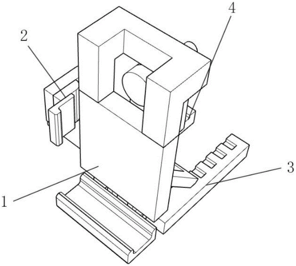
图1为本实用新型的整体结构示意图。FIG. 1 is a schematic diagram of the overall structure of the present invention.
图2为本实用新型的支撑结构示意图。FIG. 2 is a schematic diagram of the support structure of the present invention.
图3为本实用新型的固定结构示意图。FIG. 3 is a schematic diagram of the fixing structure of the present invention.
图4为本实用新型的实施例二结构示意图。FIG. 4 is a schematic structural diagram of
图5为本实用新型的实施例三结构示意图。FIG. 5 is a schematic structural diagram of
附图标记为:1、支撑机构;101、支撑背板;102、顶部支架;103、固定齿状柱;104、固定安装轴;105、固定弹簧;106、固定滑块;107、固定托架;2、固定机构;201、固定块;202、固定旋转块;203、固定复位旋转轴;204、复位弹簧;205、固定安装块;206、弹性固定块;3、底座机构;301、背部安装块;302、底部支撑轴;303、支撑架;304、底座旋转轴;305、支撑底座;4、背部机构;401、背部旋转圆柱;402、背部旋转块;403、顶部旋转柱;404、顶部旋转块;405、弹出柱;406、固定磁铁。Reference numerals are: 1. Supporting mechanism; 101. Supporting back plate; 102. Top bracket; 103. Fixed toothed column; 104. Fixed installation shaft; 105. Fixed spring; 106. Fixed slider; ;2.Fixed mechanism;201.Fixed block;202.Fixed rotating block;203.Fixed reset rotation shaft;204.Return spring;205.Fixed mounting block;206.Elastic fixed block;3.Base mechanism;301.Back mounted block; 302, bottom support shaft; 303, support frame; 304, base rotation shaft; 305, support base; 4, back mechanism; 401, back rotation cylinder; 402, back rotation block; 403, top rotation column; 404, top Rotating block; 405, ejecting column; 406, fixing magnet.
具体实施方式Detailed ways
下面将结合本新型中的附图,对本新型中的技术方案进行清楚、完整地描述,另外,在以下的实施方式中记载的各结构的形态只不过是例示,本发明所涉及的一种具备良好柔性夹持功能的手机支架并不限定于在以下的实施方式中记载的各结构,在本领域普通技术人员在没有做出创造性劳动的前提下所获得的所有其他实施方式都属于本发明保护的范围。The technical solutions of the present invention will be clearly and completely described below with reference to the accompanying drawings. In addition, the forms of the structures described in the following embodiments are only examples. The mobile phone holder with good flexible clamping function is not limited to the structures described in the following embodiments, and all other embodiments obtained by those of ordinary skill in the art without creative work belong to the protection of the present invention range.
实施例一:Example 1:
本实用新型提供了一种具备良好柔性夹持功能的手机支架,参照图1,包括支撑机构1、底座机构3,还包括:支撑机构1包括支撑背板101、顶部支架102、固定齿状柱103、固定安装轴104、固定弹簧105、固定滑块106、固定托架107;The present utility model provides a mobile phone support with good flexible clamping function. Referring to FIG. 1 , it includes a
固定机构2:安装于支撑机构1的一侧,并与支撑机构1固定连接;Fixing mechanism 2: installed on one side of the
底座机构3:安装于支撑机构1的背部,并与支撑机构1固定连接;Base mechanism 3: installed on the back of the
背部机构4:安装于支撑机构1的背部,并与支撑机构1固定连接。Back mechanism 4: installed on the back of the
参照图2,支撑背板101的顶部固定连接有顶部支架102,支撑背板101的内部活动连接有两个固定齿状柱103,固定齿状柱103之间内部活动连接有固定安装轴104,固定安装轴104的侧部活动连接有固定弹簧105,固定弹簧105的两端固定连接于固定齿状柱103的侧部,固定齿状柱103的侧部固定连接有固定滑块106,固定滑块106活动连接于固定托架107的内部,通过支撑背板101的设置,可以从后部支撑手机,通过顶部支架102的设置,可以方便手拿移动,通过固定齿状柱103的设置,通过固定安装轴104的设置,通过固定弹簧105的设置,可以移动固定高度,通过固定滑块106的设置,通过固定托架107的设置,可以托住手机底部。Referring to FIG. 2 , a
参照图2,固定机构2包括固定块201、固定旋转块202、固定复位旋转轴203、复位弹簧204、固定安装块205、弹性固定块206,固定块201固定连接于支撑背板101的侧部,固定块201的顶部活动连接有固定旋转块202,固定旋转块202的内部活动连接有固定复位旋转轴203,固定复位旋转轴203的侧部活动连接有复位弹簧204,复位弹簧204的底端固定连接于固定块201的内部,固定旋转块202的侧部固定连接有固定安装块205,固定安装块205的侧部固定连接有弹性固定块206,通过固定块201的设置,通过固定复位旋转轴203的设置,通过复位弹簧204的设置,可以将固定旋转块202旋转复位进行固定,通过固定安装块205的设置,通过弹性固定块206的设置,可以使手机侧部固定。2 , the
参照图3,底座机构3包括背部安装块301、底部支撑轴302、支撑架303、底座旋转轴304、支撑底座305,背部安装块301固定连接于支撑背板101的背部底部,背部安装块301的内部顶部固定连接有底部支撑轴302,底部支撑轴302的侧部活动连接有支撑架303,背部安装块301的内部底部固定连接有底座旋转轴304,底座旋转轴304的两侧活动连接有支撑底座305,通过背部安装块301的设置,通过底部支撑轴302的设置,通过支撑架303的设置,可以进行固定,通过底座旋转轴304的设置,通过支撑底座305的设置,可以控制设备的倾斜角度。3 , the
参照图3,背部机构4包括背部旋转圆柱401、背部旋转块402、顶部旋转柱403、顶部旋转块404、弹出柱405、固定磁铁406,背部旋转圆柱401固定连接于支撑背板101的背部,背部旋转圆柱401活动连接于背部旋转块402的内部,背部旋转块402的顶部内部活动连接有顶部旋转柱403,顶部旋转柱403活动连接于顶部旋转块404的内部,顶部旋转块404的内部活动连接有弹出柱405,弹出柱405的顶部固定连接有固定磁铁406,通过固定磁铁406的设置,可以将手机背部进行固定,通过顶部旋转柱403的设置,通过背部旋转圆柱401的设置,可以控制背部机构4的旋转。3, the
本实用新型实施例一的工作原理:装置使用时,将设备启动,挤出电机402启动,通过一重输出齿轮404带动一重带动齿轮405旋转,带动二重输出齿轮407旋转,带动二重带动齿轮408旋转,使挤出螺杆105旋转挤压,通过将主料通过主上料仓301放入,通过主放料电机303与主放料阀304控制主料投放多少,通过移动滑动放料座311确定辅料投放位置,通过副放料电机309与副放料阀310控制投放辅料的多少,通过加热旋钮103控制加热底座102的加热位置与热度,使挤出方便,通过环形加热装置202使挤出加热定型,通过内口模207与外口模204使挤出的塑胶为管状。The working principle of the first embodiment of the present utility model: when the device is in use, the device is started, the
实施例二:Embodiment 2:
参照图4,支撑机构1的两侧为平面且无任何装置,通过采用可以横向固定手机,实施例二与实施例一的区别在于:采用不设置固定机构2的方式,而不是采用固定机构2固定的方式。4 , the two sides of the
实施例三:Embodiment three:
参照图5,支撑机构1的两侧固定连接有固定机构2,通过采用两边固定机构2的固定,实施例二与实施例一的区别在于:采用两边固定机构2固定的方式,而不是采用一侧固定机构2固定设备的方式。5, the two sides of the
最后应说明的几点是:首先,在本申请的描述中,需要说明的是,除非另有规定和限定,术语“安装”、“相连”、“连接”应做广义理解,可以是机械连接或电连接,也可以是两个元件内部的连通,可以是直接相连,“上”、“下”、“左”、“右”等仅用于表示相对位置关系,当被描述对象的绝对位置改变,则相对位置关系可能发生改变;The last points to be noted are: First of all, in the description of this application, it should be noted that, unless otherwise specified and limited, the terms "installation", "connection" and "connection" should be understood in a broad sense, and may be mechanical connection. Or electrical connection, or internal communication between two elements, or direct connection, "up", "down", "left", "right", etc. are only used to indicate relative positional relationship, when the absolute position of the object to be described changes, the relative positional relationship may change;
其次:本实用新型公开实施例附图中,只涉及到与本公开实施例涉及到的结构,其他结构可参考通常设计,在不冲突情况下,本实用新型同一实施例及不同实施例可以相互组合;Secondly: in the drawings of the disclosed embodiments of the present invention, only the structures involved in the embodiments of the present invention are involved, and other structures may refer to the general design. In the case of no conflict, the same embodiment and different embodiments of the present invention can be mutually combination;
最后:以上所述仅为本实用新型的优选实施例而已,并不用于限制本实用新型,凡在本实用新型的精神和原则之内,所作的任何修改、等同替换、改进等,均应包含在本实用新型的保护范围之内。Finally: the above is only the preferred embodiment of the present utility model, and is not intended to limit the present utility model, all within the spirit and principle of the present utility model, any modification, equivalent replacement, improvement, etc. made, should include within the scope of protection of the present invention.
Claims (6)
Priority Applications (1)
| Application Number | Priority Date | Filing Date | Title |
|---|---|---|---|
| CN202122860960.3U CN216625783U (en) | 2021-11-22 | 2021-11-22 | Cell phone stand that possesses good flexible clamping function |
Applications Claiming Priority (1)
| Application Number | Priority Date | Filing Date | Title |
|---|---|---|---|
| CN202122860960.3U CN216625783U (en) | 2021-11-22 | 2021-11-22 | Cell phone stand that possesses good flexible clamping function |
Publications (1)
| Publication Number | Publication Date |
|---|---|
| CN216625783U true CN216625783U (en) | 2022-05-27 |
Family
ID=81697911
Family Applications (1)
| Application Number | Title | Priority Date | Filing Date |
|---|---|---|---|
| CN202122860960.3U Expired - Fee Related CN216625783U (en) | 2021-11-22 | 2021-11-22 | Cell phone stand that possesses good flexible clamping function |
Country Status (1)
| Country | Link |
|---|---|
| CN (1) | CN216625783U (en) |
-
2021
- 2021-11-22 CN CN202122860960.3U patent/CN216625783U/en not_active Expired - Fee Related
Similar Documents
| Publication | Publication Date | Title |
|---|---|---|
| CN110254310B (en) | Armrest for a vehicle seat and vehicle seat comprising such an armrest | |
| CN110410634A (en) | A computer display fixing seat device | |
| CN110286785B (en) | Mouse pad | |
| CN217008173U (en) | Telescopic keyboard support | |
| CN215674370U (en) | Installing support for liquid crystal display | |
| CN102133003B (en) | Stepless tilt-and-face adjusting swivel chair structure | |
| CN211186516U (en) | Sofa device with armrest adjusted through sound control | |
| CN101378640A (en) | Mechanism capable of adjusting inclination angle and horizontal rotation angle | |
| CN209400985U (en) | A kind of receipts stacked tilt adjustable type mouse support | |
| CN112664775A (en) | Horizontal marking device for interior decoration | |
| CN216556212U (en) | A metal bracket that is easy to disassemble and adjust | |
| CN210466333U (en) | Keyboard with adjustable supporting amplitude | |
| CN201060432Y (en) | Pivot device of portable computer expansion seat | |
| CN218450187U (en) | Multifunctional mobile phone holder | |
| CN208041511U (en) | A kind of shockproof bracket | |
| CN108230925B (en) | Display capable of reversing | |
| CN222209755U (en) | Integrated computer stand | |
| CN223141963U (en) | Mobile phone support with adjustable magnetic force | |
| CN214414391U (en) | Construction engineering management project budget drawing device | |
| CN222392629U (en) | Universal bracket for tablet, mobile phone and drawing board | |
| CN216795055U (en) | Vehicle-mounted mobile phone support for automobile | |
| CN219755835U (en) | Angle-adjustable display bracket | |
| CN223327376U (en) | Automobile armrest and automobile | |
| CN222597179U (en) | A vertical adjustable intercom device | |
| CN207039683U (en) | Telescopic clamping mobile phone holder |
Legal Events
| Date | Code | Title | Description |
|---|---|---|---|
| GR01 | Patent grant | ||
| GR01 | Patent grant | ||
| CF01 | Termination of patent right due to non-payment of annual fee | ||
| CF01 | Termination of patent right due to non-payment of annual fee |
Granted publication date: 20220527 |