CN216607328U - Mechanical flange perforating device - Google Patents
Mechanical flange perforating device Download PDFInfo
- Publication number
- CN216607328U CN216607328U CN202123137341.8U CN202123137341U CN216607328U CN 216607328 U CN216607328 U CN 216607328U CN 202123137341 U CN202123137341 U CN 202123137341U CN 216607328 U CN216607328 U CN 216607328U
- Authority
- CN
- China
- Prior art keywords
- fixedly connected
- servo motor
- middle end
- inner cavity
- box
- Prior art date
- Legal status (The legal status is an assumption and is not a legal conclusion. Google has not performed a legal analysis and makes no representation as to the accuracy of the status listed.)
- Expired - Fee Related
Links
- 238000004080 punching Methods 0.000 claims abstract description 25
- 238000003754 machining Methods 0.000 abstract 2
- 238000010586 diagram Methods 0.000 description 3
- 238000000034 method Methods 0.000 description 2
- 238000012986 modification Methods 0.000 description 2
- 230000004048 modification Effects 0.000 description 2
- 230000009286 beneficial effect Effects 0.000 description 1
- 238000005553 drilling Methods 0.000 description 1
- 238000004519 manufacturing process Methods 0.000 description 1
- 238000010297 mechanical methods and process Methods 0.000 description 1
Images


Landscapes
- Drilling And Boring (AREA)
Abstract
Description
技术领域technical field
本实用新型涉及机械法兰加工技术领域,具体为一种机械法兰打孔装置。The utility model relates to the technical field of mechanical flange processing, in particular to a mechanical flange punching device.
背景技术Background technique
机械法兰是轴与轴之间相互连接的零件,用于管端之间的连接;也有用在设备进出口上的法兰,用于两个设备之间的连接,而法兰在生产加工过程中需要用到打孔装置进行打孔,而现有的机械法兰打孔装置无法自动调整打孔位置,导致其使用时需要手动调节,影响加工效率,为此,我们提出一种机械法兰打孔装置。Mechanical flanges are interconnected parts between shafts and are used for the connection between pipe ends; they are also used as flanges on the inlet and outlet of equipment for the connection between two equipment, and flanges are used in production and processing. During the process, a punching device needs to be used for punching, and the existing mechanical flange punching device cannot automatically adjust the punching position, so that it needs to be manually adjusted during use, which affects the processing efficiency. For this reason, we propose a mechanical method. Lan punch device.
实用新型内容Utility model content
本实用新型的目的在于提供一种机械法兰打孔装置,具备加工效率高的优点,解决了现有的机械法兰打孔装置无法自动调整打孔位置,导致其使用时需要手动调节,影响加工效率的问题。The purpose of the utility model is to provide a mechanical flange punching device, which has the advantages of high processing efficiency, and solves the problem that the existing mechanical flange punching device cannot automatically adjust the punching position, resulting in the need for manual adjustment during use, affecting the impact of processing efficiency.
为实现上述目的,本实用新型提供如下技术方案:一种机械法兰打孔装置,包括操作台,所述操作台内腔底部的右侧固定连接有第一安装板,所述第一安装板右侧的中端固定连接有第一伺服电机,所述第一伺服电机的输出端贯穿第一安装板左侧的中端并固定连接有第一螺杆,所述第一螺杆外表面的右侧螺纹连接有第一滑块,所述第一滑块上表面的中端固定连接有固定盒,所述固定盒内腔底部的中端固定连接有第二电机盒,所述第二电机盒内腔顶部的中端固定连接有第四伺服电机,所述第四伺服电机的输出端贯穿第二电机盒上表面的中端并固定连接有转板,所述转板左右两侧的中端均开设有固定槽,所述固定槽的底部活动连接有第三辅助轮,所述第三辅助轮的外侧与固定盒内腔的左右两侧接触,所述转板内腔左右两侧的中端均固定连接有电动伸缩杆,所述电动伸缩杆的伸缩端固定连接有第三滑块,所述第三滑块上表面的中端固定连接有夹臂,所述夹臂内侧的上端固定连接有夹块。In order to achieve the above purpose, the present utility model provides the following technical solutions: a mechanical flange punching device, comprising an operating table, a first mounting plate is fixedly connected to the right side of the bottom of the inner cavity of the operating table, and the first mounting plate The middle end of the right side is fixedly connected with a first servo motor, the output end of the first servo motor penetrates the middle end of the left side of the first mounting plate and is fixedly connected with a first screw rod, the right side of the outer surface of the first screw rod is A first sliding block is threadedly connected, a fixing box is fixedly connected to the middle end of the upper surface of the first sliding block, and a second motor box is fixedly connected to the middle end of the bottom of the inner cavity of the fixing box. The middle end of the top of the cavity is fixedly connected with a fourth servo motor, the output end of the fourth servo motor penetrates the middle end of the upper surface of the second motor box and is fixedly connected with a turning plate, and the middle ends of the left and right sides of the turning plate are both A fixing slot is opened, the bottom of the fixing slot is movably connected with a third auxiliary wheel, the outer side of the third auxiliary wheel is in contact with the left and right sides of the inner cavity of the fixing box, and the middle ends of the left and right sides of the inner cavity of the turning plate are in contact with each other. They are all fixedly connected with an electric telescopic rod, the telescopic end of the electric telescopic rod is fixedly connected with a third slider, the middle end of the upper surface of the third slider is fixedly connected with a clamp arm, and the upper end of the inner side of the clamp arm is fixedly connected There are clamps.
优选的,所述操作台上表面的左侧固定连接有立柱,所述立柱内腔正面的下端固定连接有第二安装板,所述第二安装板下表面的中端固定连接有第二伺服电机,所述第二伺服电机的输出端贯穿第二安装板上表面的中端并固定连接有第二螺杆,所述第二螺杆外表面的上端螺纹连接有第二滑块。Preferably, a column is fixedly connected to the left side of the upper surface of the operating table, a second mounting plate is fixedly connected to the lower end of the front surface of the inner cavity of the column, and a second servo is fixedly connected to the middle end of the lower surface of the second mounting plate. A motor, the output end of the second servo motor penetrates the middle end of the upper surface of the second mounting plate and is fixedly connected with a second screw rod, and the upper end of the outer surface of the second screw rod is screwed with a second slider.
优选的,所述第二滑块右侧的中端固定连接有连接板,所述连接板的右侧固定连接有横杆,所述横杆下表面的右侧固定连接有第一电机盒,所述第一电机盒内腔底部的中端固定连接有第三伺服电机,所述第三伺服电机的输出端贯穿第一电机盒下表面的中端并固定连接有钻头。Preferably, a connecting plate is fixedly connected to the middle end of the right side of the second sliding block, a crossbar is fixedly connected to the right side of the connecting plate, and a first motor box is fixedly connected to the right side of the lower surface of the crossbar. The middle end of the bottom of the inner cavity of the first motor box is fixedly connected with a third servo motor, and the output end of the third servo motor penetrates the middle end of the lower surface of the first motor box and is fixedly connected with a drill bit.
优选的,所述连接板左侧的上下两端均活动连接有第一辅助轮,所述第一辅助轮的左侧与立柱的右侧接触。Preferably, the upper and lower ends of the left side of the connecting plate are movably connected with a first auxiliary wheel, and the left side of the first auxiliary wheel is in contact with the right side of the column.
优选的,所述固定盒下表面的左右两侧均活动连接有第二辅助轮,所述第二辅助轮的底端与操作台的上表面接触。Preferably, the left and right sides of the lower surface of the fixed box are movably connected with second auxiliary wheels, and the bottom ends of the second auxiliary wheels are in contact with the upper surface of the operating table.
优选的,所述操作台下表面的左右两侧均固定连接有支撑腿,所述支撑腿的底端设置有防滑垫。Preferably, the left and right sides of the lower surface of the operating table are fixedly connected with support legs, and the bottom ends of the support legs are provided with anti-skid pads.
与现有技术相比,本实用新型的有益效果如下:Compared with the prior art, the beneficial effects of the present utility model are as follows:
本实用新型设置了第四伺服电机、第一伺服电机、夹块和电动伸缩杆,通过外置控制器开启电动伸缩杆伸缩,电动伸缩杆带动第三滑块在转板的内腔左右滑动,第三滑块通过夹臂带动夹块左右滑动,将法兰夹紧,通过外置控制器开启第一伺服电机工作,第一伺服电机带动第一螺杆旋转,第一螺杆带动第一滑块在操作台的内腔左右滑动,第一滑块带动固定盒左右滑动,通过设置的第二辅助轮,可增加固定盒的稳定性,通过外置控制器开启第四伺服电机工作,第四伺服电机带动转板旋转,通过设置的第三辅助轮,可增加转板的稳定性,通过外置控制器开启第二伺服电机工作,第二伺服电机带动第二螺杆旋转,第二螺杆带动第二滑块在立柱的内腔上下滑动,第二滑块通过连接板带动横杆上下滑动,通过设置的第一辅助轮,可增加连接板的稳定性,横杆通过第一电机盒带动钻头上下滑动,达到了加工效率高的目的,解决了现有的机械法兰打孔装置无法自动调整打孔位置,导致其使用时需要手动调节,影响加工效率的问题。The utility model is provided with a fourth servo motor, a first servo motor, a clamping block and an electric telescopic rod. The electric telescopic rod is started to telescopic through an external controller, and the electric telescopic rod drives the third sliding block to slide left and right in the inner cavity of the rotating plate. The third sliding block drives the clamping block to slide left and right through the clamping arm to clamp the flange, and the first servo motor is turned on through the external controller to work. The first servo motor drives the first screw to rotate, and the first screw drives the first slider to move The inner cavity of the operating table slides left and right, and the first slider drives the fixed box to slide left and right. The stability of the fixed box can be increased through the second auxiliary wheel. The fourth servo motor is turned on by the external controller to work, and the fourth servo motor Drive the rotating plate to rotate, the stability of the rotating plate can be increased through the set third auxiliary wheel, the second servo motor is turned on by the external controller, the second servo motor drives the second screw to rotate, and the second screw drives the second sliding The block slides up and down in the inner cavity of the column, the second slider drives the cross bar to slide up and down through the connecting plate, and the stability of the connecting plate can be increased by the first auxiliary wheel provided, and the cross bar drives the drill bit to slide up and down through the first motor box, The purpose of high processing efficiency is achieved, and the problem that the existing mechanical flange punching device cannot automatically adjust the punching position, resulting in the need for manual adjustment during use and affecting the processing efficiency.
附图说明Description of drawings
图1为本实用新型主视结构示意图;Fig. 1 is the front view structure schematic diagram of the utility model;
图2为本实用新型剖视结构示意图;Fig. 2 is the sectional structure schematic diagram of the utility model;
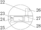
图3为本实用新型A处放大结构示意图。Figure 3 is a schematic diagram of the enlarged structure of the utility model A.
图中:1、操作台;2、支撑腿;3、钻头;4、第一辅助轮;5、立柱;6、横杆;7、第一电机盒;8、固定盒;9、第二辅助轮;10、第一螺杆;11、第二伺服电机;12、第二安装板;13、第二螺杆;14、第二滑块;15、连接板;16、第三伺服电机;17、第四伺服电机;18、第二电机盒;19、第一伺服电机;20、第一安装板;21、第一滑块;22、夹臂;23、固定槽;24、第三辅助轮;25、转板;26、夹块;27、第三滑块;28、电动伸缩杆。In the figure: 1. console; 2. support leg; 3. drill bit; 4. first auxiliary wheel; 5. column; 6. cross bar; 7. first motor box; 8. fixed box; 9. second auxiliary wheel; 10, the first screw; 11, the second servo motor; 12, the second mounting plate; 13, the second screw; 14, the second slider; 15, the connecting plate; 16, the third servo motor; 17, the first Four servo motors; 18, the second motor box; 19, the first servo motor; 20, the first mounting plate; 21, the first slider; 22, the clamping arm; 23, the fixing slot; 24, the third auxiliary wheel; 25 , Rotary plate; 26, clamping block; 27, the third slider; 28, electric telescopic rod.
具体实施方式Detailed ways
下面将结合本实用新型实施例中的附图,对本实用新型实施例中的技术方案进行清楚、完整地描述,显然,所描述的实施例仅仅是本实用新型一部分实施例,而不是全部的实施例。基于本实用新型中的实施例,本领域普通技术人员在没有做出创造性劳动前提下所获得的所有其他实施例,都属于本实用新型保护的范围。The technical solutions in the embodiments of the present utility model will be clearly and completely described below with reference to the accompanying drawings in the embodiments of the present utility model. Obviously, the described embodiments are only a part of the embodiments of the present utility model, rather than all the implementations. example. Based on the embodiments of the present invention, all other embodiments obtained by those of ordinary skill in the art without creative work fall within the protection scope of the present invention.
请参阅图1-3,一种机械法兰打孔装置,包括操作台1,操作台1上表面的左侧固定连接有立柱5,立柱5内腔正面的下端固定连接有第二安装板12,第二安装板12下表面的中端固定连接有第二伺服电机11,第二伺服电机11的输出端贯穿第二安装板12上表面的中端并固定连接有第二螺杆13,第二螺杆13外表面的上端螺纹连接有第二滑块14,第二滑块14右侧的中端固定连接有连接板15,连接板15的右侧固定连接有横杆6,横杆6下表面的右侧固定连接有第一电机盒7,第一电机盒7内腔底部的中端固定连接有第三伺服电机16,第三伺服电机16的输出端贯穿第一电机盒7下表面的中端并固定连接有钻头3,连接板15左侧的上下两端均活动连接有第一辅助轮4,第一辅助轮4的左侧与立柱5的右侧接触,操作台1下表面的左右两侧均固定连接有支撑腿2,支撑腿2的底端设置有防滑垫,操作台1内腔底部的右侧固定连接有第一安装板20,第一安装板20右侧的中端固定连接有第一伺服电机19,第一伺服电机19的输出端贯穿第一安装板20左侧的中端并固定连接有第一螺杆10,第一螺杆10外表面的右侧螺纹连接有第一滑块21,第一滑块21上表面的中端固定连接有固定盒8,固定盒8下表面的左右两侧均活动连接有第二辅助轮9,第二辅助轮9的底端与操作台1的上表面接触,固定盒8内腔底部的中端固定连接有第二电机盒18,第二电机盒18内腔顶部的中端固定连接有第四伺服电机17,第四伺服电机17的输出端贯穿第二电机盒18上表面的中端并固定连接有转板25,转板25左右两侧的中端均开设有固定槽23,固定槽23的底部活动连接有第三辅助轮24,第三辅助轮24的外侧与固定盒8内腔的左右两侧接触,转板25内腔左右两侧的中端均固定连接有电动伸缩杆28,电动伸缩杆28的伸缩端固定连接有第三滑块27,第三滑块27上表面的中端固定连接有夹臂22,夹臂22内侧的上端固定连接有夹块26,设置了第四伺服电机17、第一伺服电机19、夹块26和电动伸缩杆28,通过外置控制器开启电动伸缩杆28伸缩,电动伸缩杆28带动第三滑块27在转板25的内腔左右滑动,第三滑块27通过夹臂22带动夹块26左右滑动,将法兰夹紧,通过外置控制器开启第一伺服电机19工作,第一伺服电机19带动第一螺杆10旋转,第一螺杆10带动第一滑块21在操作台1的内腔左右滑动,第一滑块21带动固定盒8左右滑动,通过设置的第二辅助轮9,可增加固定盒8的稳定性,通过外置控制器开启第四伺服电机17工作,第四伺服电机17带动转板25旋转,通过设置的第三辅助轮24,可增加转板25的稳定性,通过外置控制器开启第二伺服电机11工作,第二伺服电机11带动第二螺杆13旋转,第二螺杆13带动第二滑块14在立柱5的内腔上下滑动,第二滑块14通过连接板15带动横杆6上下滑动,通过设置的第一辅助轮4,可增加连接板15的稳定性,横杆6通过第一电机盒7带动钻头3上下滑动,达到了加工效率高的目的。Please refer to Figure 1-3, a mechanical flange drilling device, including an operating table 1, a
使用时,设置了第四伺服电机17、第一伺服电机19、夹块26和电动伸缩杆28,通过外置控制器开启电动伸缩杆28伸缩,电动伸缩杆28带动第三滑块27在转板25的内腔左右滑动,第三滑块27通过夹臂22带动夹块26左右滑动,将法兰夹紧,通过外置控制器开启第一伺服电机19工作,第一伺服电机19带动第一螺杆10旋转,第一螺杆10带动第一滑块21在操作台1的内腔左右滑动,第一滑块21带动固定盒8左右滑动,通过设置的第二辅助轮9,可增加固定盒8的稳定性,通过外置控制器开启第四伺服电机17工作,第四伺服电机17带动转板25旋转,通过设置的第三辅助轮24,可增加转板25的稳定性,通过外置控制器开启第二伺服电机11工作,第二伺服电机11带动第二螺杆13旋转,第二螺杆13带动第二滑块14在立柱5的内腔上下滑动,第二滑块14通过连接板15带动横杆6上下滑动,通过设置的第一辅助轮4,可增加连接板15的稳定性,横杆6通过第一电机盒7带动钻头3上下滑动,达到了加工效率高的目的,解决了现有的机械法兰打孔装置无法自动调整打孔位置,导致其使用时需要手动调节,影响加工效率的问题。When in use, the
尽管已经示出和描述了本实用新型的实施例,对于本领域的普通技术人员而言,可以理解在不脱离本实用新型的原理和精神的情况下可以对这些实施例进行多种变化、修改、替换和变型,本实用新型的范围由所附权利要求及其等同物限定。Although the embodiments of the present invention have been shown and described, it will be understood by those skilled in the art that various changes and modifications can be made to these embodiments without departing from the principles and spirit of the present invention , alternatives and modifications, the scope of the present invention is defined by the appended claims and their equivalents.
Claims (6)
Priority Applications (1)
| Application Number | Priority Date | Filing Date | Title |
|---|---|---|---|
| CN202123137341.8U CN216607328U (en) | 2021-12-14 | 2021-12-14 | Mechanical flange perforating device |
Applications Claiming Priority (1)
| Application Number | Priority Date | Filing Date | Title |
|---|---|---|---|
| CN202123137341.8U CN216607328U (en) | 2021-12-14 | 2021-12-14 | Mechanical flange perforating device |
Publications (1)
| Publication Number | Publication Date |
|---|---|
| CN216607328U true CN216607328U (en) | 2022-05-27 |
Family
ID=81702929
Family Applications (1)
| Application Number | Title | Priority Date | Filing Date |
|---|---|---|---|
| CN202123137341.8U Expired - Fee Related CN216607328U (en) | 2021-12-14 | 2021-12-14 | Mechanical flange perforating device |
Country Status (1)
| Country | Link |
|---|---|
| CN (1) | CN216607328U (en) |
-
2021
- 2021-12-14 CN CN202123137341.8U patent/CN216607328U/en not_active Expired - Fee Related
Similar Documents
| Publication | Publication Date | Title |
|---|---|---|
| CN206732188U (en) | A kind of special air stream drives formula rig of machine-building | |
| CN111673127B (en) | A multi-directional adjustable arc hardware plate clamping and punching mechanism | |
| CN209867475U (en) | Planer type milling machine for processing flange | |
| CN216576736U (en) | Formula lathe anchor clamps are adjusted to multi-angle | |
| CN219521702U (en) | An automatic steel pipe polishing machine | |
| CN221834012U (en) | A workpiece flushing and cooling device for the grinding area of a vertical grinder | |
| CN219484288U (en) | A machining drilling device | |
| CN217776084U (en) | Two-axis linkage robot positioner | |
| CN218363455U (en) | Oil pump rotor positioning tool | |
| CN217913357U (en) | Numerical control plasma cutting machine of quick location | |
| CN218904335U (en) | Lifting table milling machine for equipment part production | |
| CN209319936U (en) | An automatic punching machine for plastic profiles | |
| CN223466184U (en) | Clamping tool for processing impeller shell of air compressor | |
| CN222308122U (en) | E-type bolt milling equipment for scraper conveyor | |
| CN221834678U (en) | A kind of auxiliary device for weak current installation of building | |
| CN219043767U (en) | A clamping device for a worktable of a radial drilling machine | |
| CN221817388U (en) | Drilling device for flange production | |
| CN219425525U (en) | A kind of construction steel bar cutting equipment | |
| CN221792392U (en) | A clamping device for equipment maintenance | |
| CN218904644U (en) | A corner processing device for processing mechanical parts | |
| CN219402568U (en) | Metal support adds clamping apparatus | |
| CN221891411U (en) | A double-sided milling machine device for flattening drill rod joints | |
| CN219543341U (en) | Cutting device for production and processing of burglary-resisting door | |
| CN219562464U (en) | All-round burring equipment in surface of metal member | |
| CN221936672U (en) | Aluminum part machining tool |
Legal Events
| Date | Code | Title | Description |
|---|---|---|---|
| GR01 | Patent grant | ||
| GR01 | Patent grant | ||
| CF01 | Termination of patent right due to non-payment of annual fee |
Granted publication date: 20220527 |
|
| CF01 | Termination of patent right due to non-payment of annual fee |