CN216597697U - Vertical lamination machine and cell manufacturing equipment - Google Patents

Vertical lamination machine and cell manufacturing equipment Download PDF

Info

Publication number
CN216597697U
CN216597697U CN202123335807.5U CN202123335807U CN216597697U CN 216597697 U CN216597697 U CN 216597697U CN 202123335807 U CN202123335807 U CN 202123335807U CN 216597697 U CN216597697 U CN 216597697U
Authority
CN
China
Prior art keywords
lamination
vertical
diaphragm
plate
frame
Prior art date
Legal status (The legal status is an assumption and is not a legal conclusion. Google has not performed a legal analysis and makes no representation as to the accuracy of the status listed.)
Active
Application number
CN202123335807.5U
Other languages
Chinese (zh)
Inventor
漆磊
李核志
Current Assignee (The listed assignees may be inaccurate. Google has not performed a legal analysis and makes no representation or warranty as to the accuracy of the list.)
Sany Technology Equipment Co Ltd
Original Assignee
Sany Technology Equipment Co Ltd
Priority date (The priority date is an assumption and is not a legal conclusion. Google has not performed a legal analysis and makes no representation as to the accuracy of the date listed.)
Filing date
Publication date
Application filed by Sany Technology Equipment Co Ltd filed Critical Sany Technology Equipment Co Ltd
Priority to CN202123335807.5U priority Critical patent/CN216597697U/en
Application granted granted Critical
Publication of CN216597697U publication Critical patent/CN216597697U/en
Active legal-status Critical Current
Anticipated expiration legal-status Critical

Links

Images

Classifications

    • Y—GENERAL TAGGING OF NEW TECHNOLOGICAL DEVELOPMENTS; GENERAL TAGGING OF CROSS-SECTIONAL TECHNOLOGIES SPANNING OVER SEVERAL SECTIONS OF THE IPC; TECHNICAL SUBJECTS COVERED BY FORMER USPC CROSS-REFERENCE ART COLLECTIONS [XRACs] AND DIGESTS
    • Y02—TECHNOLOGIES OR APPLICATIONS FOR MITIGATION OR ADAPTATION AGAINST CLIMATE CHANGE
    • Y02E—REDUCTION OF GREENHOUSE GAS [GHG] EMISSIONS, RELATED TO ENERGY GENERATION, TRANSMISSION OR DISTRIBUTION
    • Y02E60/00—Enabling technologies; Technologies with a potential or indirect contribution to GHG emissions mitigation
    • Y02E60/10—Energy storage using batteries
    • Y—GENERAL TAGGING OF NEW TECHNOLOGICAL DEVELOPMENTS; GENERAL TAGGING OF CROSS-SECTIONAL TECHNOLOGIES SPANNING OVER SEVERAL SECTIONS OF THE IPC; TECHNICAL SUBJECTS COVERED BY FORMER USPC CROSS-REFERENCE ART COLLECTIONS [XRACs] AND DIGESTS
    • Y02—TECHNOLOGIES OR APPLICATIONS FOR MITIGATION OR ADAPTATION AGAINST CLIMATE CHANGE
    • Y02P—CLIMATE CHANGE MITIGATION TECHNOLOGIES IN THE PRODUCTION OR PROCESSING OF GOODS
    • Y02P70/00—Climate change mitigation technologies in the production process for final industrial or consumer products
    • Y02P70/50—Manufacturing or production processes characterised by the final manufactured product

Landscapes

  • Secondary Cells (AREA)

Abstract

本实用新型涉及锂电池制造技术领域,具体涉及一种立式叠片机及电芯制造设备。立式叠片机包括:机架,包括立板;隔膜放卷装置,设置在立板上且用于放卷隔膜;叠片装置,设置在立板上,叠片装置对隔膜进行Z字形折叠且将正极片、负极片交替叠放在隔膜上,以形成叠片。本实用新型将隔膜放卷装置和叠片装置设置在垂直于水平面的立板上,即叠片机采用立式结构,充分利用竖向空间,极大的减少了叠片的空间和占地面积,且在立板的两侧对立式叠片机进行维护,维护方便。
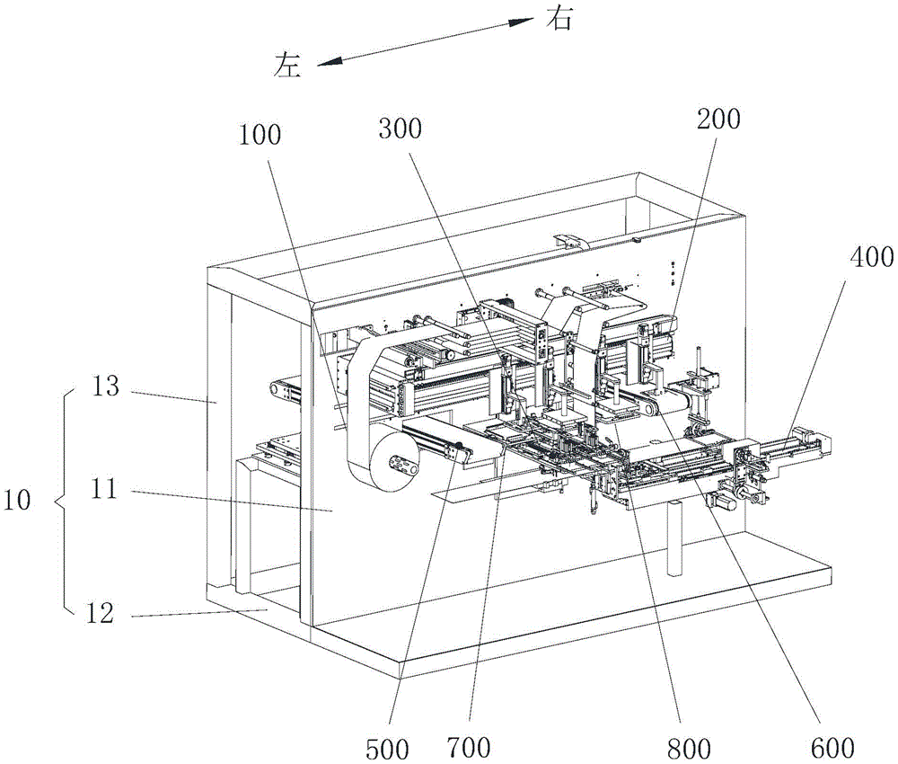
Figure 202123335807

The utility model relates to the technical field of lithium battery manufacturing, in particular to a vertical lamination machine and battery core manufacturing equipment. The vertical laminating machine includes: a frame, including a vertical plate; a diaphragm unwinding device, which is arranged on the vertical plate and is used for unwinding the diaphragm; And the positive electrode sheet and the negative electrode sheet are alternately stacked on the separator to form a stack. In the utility model, the diaphragm unwinding device and the lamination device are arranged on the vertical plate perpendicular to the horizontal plane, that is, the lamination machine adopts a vertical structure, makes full use of the vertical space, and greatly reduces the space and floor space of the lamination. , and the vertical lamination machine is maintained on both sides of the vertical plate, which is convenient for maintenance.

Figure 202123335807

Description

立式叠片机及电芯制造设备Vertical lamination machine and cell manufacturing equipment

技术领域technical field

本实用新型涉及锂电池制造技术领域,具体涉及一种立式叠片机及电芯制造设备。The utility model relates to the technical field of lithium battery manufacturing, in particular to a vertical lamination machine and battery core manufacturing equipment.

背景技术Background technique

目前,锂离子电池的电芯包括正极片、负极片及隔膜,锂离子电池中电芯的生产工艺一般有两种,一种为卷绕工艺,另一种为叠片工艺。叠片工艺通常采用叠片机,叠片机通过隔膜将正负极片间隔叠置形成电芯,叠片工艺生产的电芯具有容量高、内阻小的优点,且叠片工艺能够生产多种形状的电芯,可根据实际需求进行设定。At present, the cells of lithium ion batteries include positive electrode sheets, negative electrode sheets and separators. There are generally two production processes for cells in lithium ion batteries, one is a winding process, and the other is a lamination process. The lamination process usually uses a lamination machine. The lamination machine stacks the positive and negative plates at intervals through the diaphragm to form cells. The cells produced by the lamination process have the advantages of high capacity and low internal resistance, and the lamination process can produce many Various shapes of cells can be set according to actual needs.

现有技术中,叠片机采用卧式结构,平面占地面积大。In the prior art, the lamination machine adopts a horizontal structure, and the plane occupies a large area.

实用新型内容Utility model content

因此,本实用新型要解决的技术问题在于克服现有技术中的叠片机采用卧式结构造成平面占地面积大的缺陷,从而提供一种立式叠片机及电芯制造设备。Therefore, the technical problem to be solved by the present invention is to overcome the defect that the horizontal structure of the lamination machine in the prior art results in a large floor area, thereby providing a vertical lamination machine and cell manufacturing equipment.

为了解决上述问题,本实用新型提供了一种立式叠片机,包括:机架,包括立板;隔膜放卷装置,设置在立板上且用于放卷隔膜;叠片装置,设置在立板上,叠片装置对隔膜进行Z字形折叠且将正极片、负极片交替叠放在隔膜上,以形成叠片。In order to solve the above problems, the utility model provides a vertical lamination machine, comprising: a frame, including a vertical plate; a diaphragm unwinding device, which is arranged on the vertical plate and is used for unwinding the diaphragm; On the vertical plate, the stacking device folds the separator in a zigzag shape and alternately stacks the positive electrode sheet and the negative electrode sheet on the separator to form a stacked sheet.

可选的,叠片装置包括叠台装置,叠台装置包括叠片台和第二升降结构,第二升降结构与叠片台连接且驱动叠片台沿竖向移动,以在同一高度位置且在叠片台上进行叠片。Optionally, the stacking device includes a stacking device, the stacking device includes a stacking table and a second lifting structure, the second lifting structure is connected with the stacking table and drives the stacking table to move vertically, so as to be at the same height position and Lamination is performed on the lamination table.

可选的,叠片装置还包括极片抓取装置,极片抓取装置设置在立板的上部,叠台装置设置在立板的中部,隔膜放卷装置的隔膜摆动机构固定在极片抓取装置上且其余部件设置在极片抓取装置远离叠台装置的至少一侧。Optionally, the stacking device further includes a pole piece grabbing device, the pole piece grabbing device is arranged on the upper part of the vertical plate, the stacking device is arranged in the middle of the vertical plate, and the diaphragm swing mechanism of the diaphragm unwinding device is fixed on the pole piece grabbing device. and the remaining components are arranged on at least one side of the pole piece grabbing device away from the stacking device.

可选的,极片抓取装置包括移动驱动结构、升降驱动结构及极片抓取机构,移动驱动结构设置在立板上且适于驱动极片抓取机构沿横向往复移动,升降驱动结构设置在移动驱动结构上且与极片抓取机构连接,升降驱动结构适于驱动极片抓取机构沿竖向移动,其中,横向为立板的水平延伸方向。Optionally, the pole piece grasping device includes a moving driving structure, a lifting driving structure and a pole piece grasping mechanism. The moving driving structure is arranged on the vertical plate and is suitable for driving the pole piece grasping mechanism to reciprocate along the lateral direction. The lifting driving structure is provided. On the moving drive structure and connected with the pole piece grabbing mechanism, the elevating drive structure is suitable for driving the pole piece grabbing mechanism to move vertically, wherein the transverse direction is the horizontal extension direction of the vertical plate.

可选的,立式叠片机还包括正极片输送装置和负极片输送装置,正极片输送装置和负极片输送装置贯穿立板上且分设于叠台装置的两侧。Optionally, the vertical stacking machine further includes a positive electrode sheet conveying device and a negative electrode sheet conveying device, and the positive electrode sheet conveying device and the negative electrode sheet conveying device pass through the vertical plate and are located on both sides of the stacking device.

可选的,立式叠片机还包括正极片纠偏装置和负极片纠偏装置,正极片纠偏装置和负极片纠偏装置设置在立板上,正极片纠偏装置位于正极片输送装置和叠台装置之间,负极片纠偏装置设置在负极片输送装置和叠台装置之间。Optionally, the vertical lamination machine further includes a positive electrode sheet deviation correction device and a negative electrode sheet deviation correction device, the positive electrode sheet deviation correction device and the negative electrode sheet deviation correction device are arranged on the vertical plate, and the positive electrode sheet deviation correction device is located between the positive electrode sheet conveying device and the stacking device. During this time, the negative electrode sheet deviation correction device is arranged between the negative electrode sheet conveying device and the stacking device.

可选的,立式叠片机还包括尾卷装置,尾卷装置设置在立板上且用于对叠片后的电芯进行尾卷。Optionally, the vertical lamination machine further includes a tail winding device, which is arranged on the vertical plate and is used for tail winding the stacked cells.

可选的,尾卷装置设置在叠台装置的一侧且位于叠台装置的斜下方。Optionally, the tail winding device is arranged on one side of the stacking device and is located obliquely below the stacking device.

可选的,机架还包括支撑架,立板固定在支撑架上,隔膜放卷装置中的部件分设于立板的两侧。Optionally, the frame further includes a support frame, the vertical plate is fixed on the support frame, and the components in the diaphragm unwinding device are arranged on both sides of the vertical plate.

可选的,支撑架包括底架和侧架,立板设置在底架的中部,侧架设置在底架上且位于立板的一侧,立板固定在侧架的侧面上。Optionally, the support frame includes a bottom frame and a side frame, the vertical plate is disposed in the middle of the bottom frame, the side frame is disposed on the bottom frame and is located on one side of the vertical plate, and the vertical plate is fixed on the side surface of the side frame.

可选的,叠台装置还包括:至少两个压刀机构,对应叠片台并排设置,每个压刀机构包括相对设置的两个压刀组件,压刀机构适于对隔膜和/或极片进行按压;至少两个开合机构,与至少两个压刀机构一一对应设置,每个开合机构包括相对间隔设置的两个齿条、同时与两个齿条啮合设置的齿轮以及驱动部件,两个齿条分别与对应的两个压刀组件相连接,驱动部件与齿轮连接,在驱动部件的驱动下,两个压刀组件能够沿第一方向相互靠近或相互远离运动。Optionally, the table stacking device further includes: at least two knife press mechanisms, which are arranged side by side corresponding to the lamination tables, each knife press mechanism includes two oppositely arranged knife press assemblies, and the knife press mechanisms are suitable for the diaphragm and/or pole. The plate is pressed; at least two opening and closing mechanisms are provided in one-to-one correspondence with at least two knife pressing mechanisms, and each opening and closing mechanism includes two racks arranged at opposite intervals, a gear engaged with the two racks at the same time, and a drive The two gear racks are respectively connected with the corresponding two pressing knife assemblies, the driving part is connected with the gears, and driven by the driving part, the two pressing knife assemblies can move toward or away from each other along the first direction.

可选的,每个压刀组件包括压刀座、压刀架、压刀本体、第一升降结构和调节结构,压刀座与对应的齿条连接,压刀架可移动地设置在压刀座上,压刀本体朝向叠片台设置,第一升降结构设置在压刀架上且与压刀本体连接,第一升降结构适于驱动压刀本体沿竖向移动,调节结构设置在压刀座上且与压刀架连接,调节结构适于沿第二方向调整压刀本体的位置,其中,第二方向垂直于第一方向。Optionally, each knife-pressing assembly includes a knife-pressing seat, a knife-pressing frame, a knife-pressing body, a first lifting structure and an adjusting structure, the knife-pressing seat is connected with the corresponding rack, and the knife-pressing frame is movably arranged on the pressing-knife. On the seat, the pressing knife body is arranged towards the lamination table, the first lifting structure is arranged on the pressing knife frame and is connected with the pressing knife body, the first lifting structure is suitable for driving the pressing knife body to move vertically, and the adjusting structure is arranged on the pressing knife body. The seat is connected to the blade holder, and the adjustment structure is suitable for adjusting the position of the blade body along a second direction, wherein the second direction is perpendicular to the first direction.

可选的,压刀组件还包括与压刀架滑动连接的升降板,压刀本体设置于升降板上,第一升降结构包括第一磁体和第二磁体,其中,第一磁体和/或第二磁体为电磁体,第一磁体和第二磁体分别设置于升降板和压刀架上,且第一磁体和第二磁体相对设置,第一升降结构还包括电源,电源设置于压刀架上且与电磁体电连接,第一磁体和第二磁体能够相互吸引或相互排斥,以驱动升降板沿压刀架升降。Optionally, the knife press assembly further includes a lift plate slidably connected to the knife press frame, the knife press body is disposed on the lift plate, and the first lift structure includes a first magnet and a second magnet, wherein the first magnet and/or the first magnet The two magnets are electromagnets. The first magnet and the second magnet are respectively arranged on the lifting plate and the tool holder, and the first magnet and the second magnet are arranged opposite to each other. The first lifting structure also includes a power source, and the power source is arranged on the tool holder. And being electrically connected with the electromagnet, the first magnet and the second magnet can attract or repel each other, so as to drive the lifting plate to move up and down along the knife holder.

可选的,调节结构包括第一丝杆,第一丝杆与压刀座可转动连接,并且第一丝杆与压刀架螺纹连接。Optionally, the adjustment structure includes a first screw rod, the first screw rod is rotatably connected to the knife holder, and the first screw rod is threadedly connected to the knife holder.

可选的,压刀组件还包括限位结构,限位结构适于对压刀本体沿竖向移动的极限位置进行限制。Optionally, the pressing knife assembly further includes a limiting structure, and the limiting structure is suitable for limiting the limit position of the vertical movement of the pressing knife body.

可选的,每个开合机构还包括两个第一滑轨和两个开合滑板,两个齿条、两个第一滑轨及两个开合滑板一一对应设置,齿条设置于开合滑板上,压刀组件设置于开合滑板上。Optionally, each opening and closing mechanism further includes two first sliding rails and two opening and closing sliding plates, the two racks, the two first sliding rails, and the two opening and closing sliding plates are arranged in a one-to-one correspondence, and the racks are arranged in a one-to-one correspondence. On the opening and closing slide plate, the pressing knife assembly is arranged on the opening and closing slide plate.

可选的,叠片台上的两个侧部中的至少一个处开设有避空槽。Optionally, at least one of the two side portions on the lamination table is provided with a hollow slot.

可选的,叠台装置还包括安装台和叠台机构,叠台机构设置于安装台上,叠台机构包括叠片台和第二升降结构,第二升降结构设置在安装台上。Optionally, the stacking device further includes a mounting table and a stacking mechanism, the stacking mechanism is arranged on the mounting table, the stacking mechanism includes a stacking table and a second lifting structure, and the second lifting structure is arranged on the mounting table.

可选的,叠台装置还包括第三升降结构,第三升降结构适于设置在机架上且驱动安装台沿竖向移动。Optionally, the table stacking device further includes a third lifting structure, and the third lifting structure is suitable for being disposed on the frame and driving the installation platform to move vertically.

可选的,叠台装置还包括:叠台架,叠台架设置在机架的立板上,叠台架包括安装台和叠台竖板,安装台垂直于立板设置,叠台竖板与立板平行设置且与安装台连接。Optionally, the platform stacking device further includes: a stacking platform, the stacking platform is arranged on the vertical plate of the rack, the stacking platform includes a mounting platform and a stacking vertical plate, the mounting platform is arranged perpendicular to the vertical plate, and the stacking vertical plate is arranged. It is arranged in parallel with the vertical plate and connected with the installation table.

可选的,叠台架还包括加强板,加强板连接在叠台竖板和安装台之间。Optionally, the stacking platform further includes a reinforcing plate, and the reinforcing plate is connected between the stacking platform vertical plate and the installation platform.

可选的,隔膜放卷装置包括:放卷机构,设置于机架上,适于放置隔膜卷并对隔膜卷进行放料;张力调节机构,设置于机架上,张力调节机构为弹性结构,在张力调节机构的弹性力作用下适于调节隔膜的张紧度。Optionally, the diaphragm unwinding device includes: an unwinding mechanism, arranged on the frame, suitable for placing the diaphragm roll and discharging the diaphragm roll; a tension adjusting mechanism, arranged on the frame, and the tension adjusting mechanism is an elastic structure, It is suitable for adjusting the tension of the diaphragm under the action of the elastic force of the tension adjusting mechanism.

可选的,张力调节机构包括调节滑块、张紧辊和弹性件,调节滑块与机架可滑动连接,张紧辊设置于调节滑块上,弹性件设置于调节滑块和机架之间。Optionally, the tension adjustment mechanism includes an adjustment slider, a tension roller and an elastic member, the adjustment slider is slidably connected to the frame, the tension roller is arranged on the adjustment slider, and the elastic member is arranged between the adjustment slider and the frame. between.

本实用新型还提供了一种电芯制造设备,包括上述的立式叠片机。The utility model also provides an electric core manufacturing equipment, including the above-mentioned vertical lamination machine.

本实用新型具有以下优点:The utility model has the following advantages:

将隔膜放卷装置和叠片装置设置在垂直于水平面的立板上,即叠片机采用立式结构,充分利用竖向空间,极大的减少了叠片的空间和占地面积,且在立板的两侧对立式叠片机进行维护,维护方便。The diaphragm unwinding device and the lamination device are arranged on the vertical plate perpendicular to the horizontal plane, that is, the lamination machine adopts a vertical structure, making full use of the vertical space, greatly reducing the space and area of the lamination, and in the The vertical lamination machine is maintained on both sides of the vertical plate, which is convenient for maintenance.

附图说明Description of drawings

为了更清楚地说明本实用新型具体实施方式或现有技术中的技术方案,下面将对具体实施方式或现有技术描述中所需要使用的附图作简单地介绍,显而易见地,下面描述中的附图是本实用新型的一些实施方式,对于本领域普通技术人员来讲,在不付出创造性劳动的前提下,还可以根据这些附图获得其他的附图。In order to more clearly illustrate the specific embodiments of the present invention or the technical solutions in the prior art, the following will briefly introduce the accompanying drawings that need to be used in the description of the specific embodiments or the prior art. Obviously, the following descriptions The accompanying drawings are some embodiments of the present invention. For those of ordinary skill in the art, other drawings can also be obtained based on these drawings without creative efforts.

图1示出了本实用新型实施例的立式叠片机的立体示意图;Fig. 1 shows a three-dimensional schematic diagram of a vertical lamination machine according to an embodiment of the present invention;

图2示出了图1的立式叠片机的第一角度的立体示意图;FIG. 2 shows a schematic perspective view of the vertical lamination machine of FIG. 1 from a first angle;

图3示出了图1的立式叠片机的隔膜放卷装置的立体示意图;FIG. 3 shows a schematic perspective view of the diaphragm unwinding device of the vertical lamination machine of FIG. 1;

图4示出了图1的立式叠片机的隔膜放卷装置和机架的立体示意图;FIG. 4 shows a schematic perspective view of the diaphragm unwinding device and the frame of the vertical lamination machine of FIG. 1;

图5示出了图4的隔膜放卷装置和机架的主视示意图;Figure 5 shows a schematic front view of the diaphragm unwinding device and frame of Figure 4;

图6示出了图5的隔膜放卷装置的张力调节机构的示意图;Fig. 6 shows the schematic diagram of the tension adjustment mechanism of the diaphragm unwinding device of Fig. 5;

图7示出了图1的立式叠片机的极片抓取装置的主视示意图;FIG. 7 shows a schematic front view of the pole piece grabbing device of the vertical lamination machine of FIG. 1;

图8示出了图7的极片抓取装置的另一角度的立体示意图;Fig. 8 shows a perspective view of another angle of the pole piece grabbing device of Fig. 7;

图9示出了图1的立式叠片机的第二角度的立体示意图;FIG. 9 shows a schematic perspective view of the vertical lamination machine of FIG. 1 from a second angle;

图10示出了图9的立式叠片机的部分示意图;Figure 10 shows a partial schematic view of the vertical stacker of Figure 9;

图11示出了10的立式叠片机的机架和叠台装置的立体示意图;FIG. 11 shows a perspective view of the frame and the stacking device of the vertical stacker of 10;

图12示出了图11的叠台装置的第一角度的立体示意图;FIG. 12 shows a schematic perspective view of the stacking device of FIG. 11 from a first angle;

图13示出了图11的叠台装置的第二角度的立体示意图;Figure 13 shows a schematic perspective view of the second angle of the stacking device of Figure 11;

图14示出了图11的叠台装置的第三角度的立体示意图;Fig. 14 shows a perspective view of the third angle of the stacking device of Fig. 11;

图15示出了图14的叠台装置的部分示意图;Figure 15 shows a partial schematic view of the stacking device of Figure 14;

图16示出了图15的叠台装置的A处的放大示意图;Fig. 16 shows an enlarged schematic view of the position A of the stacking device of Fig. 15;

图17示出了图15的叠台装置的开合机构的主视示意图;Fig. 17 shows a schematic front view of the opening and closing mechanism of the table stacking device of Fig. 15;

图18示出了图17的开合机构的俯视示意图;Figure 18 shows a schematic top view of the opening and closing mechanism of Figure 17;

图19示出了图17的开合机构的左视示意图;Fig. 19 shows a left side schematic view of the opening and closing mechanism of Fig. 17;

图20示出了图14的压刀组件的第一角度的立体示意图;Fig. 20 shows a perspective view of the first angle of the pressing knife assembly of Fig. 14;

图21示出了图14的压刀组件的第二角度的立体示意图;Fig. 21 shows a perspective view of the second angle of the pressing knife assembly of Fig. 14;

图22示出了图20的压刀组件的主视示意图。FIG. 22 shows a schematic front view of the press knife assembly of FIG. 20 .

图23示出了图1的立式叠片机的机架、尾卷装置及叠台装置的立体示意图;FIG. 23 shows a schematic perspective view of the frame, the tail winding device and the stacking device of the vertical stacker of FIG. 1;

图24示出了图23的尾卷装置的取料机构处于取料状态的立体示意图;Figure 24 shows a schematic perspective view of the reclaiming mechanism of the tailwinding device of Figure 23 in a reclaiming state;

图25示出了图23的尾卷装置的取料机构靠近缠绕机构的立体示意图;Figure 25 shows a schematic perspective view of the reclaiming mechanism of the tail winding device of Figure 23 approaching the winding mechanism;

图26示出了图25的尾卷装置的B处的放大示意图;Figure 26 shows an enlarged schematic view of the tail winding device of Figure 25 at B;

图27示出了图26的尾卷装置的D处的放大示意图;FIG. 27 shows an enlarged schematic view of the tail winding device at D of FIG. 26;

图28示出了图25的尾卷装置的C处的放大示意图;FIG. 28 shows an enlarged schematic view of the tail winding device of FIG. 25 at C;

图29示出了图1的立式叠片机的正极片纠偏装置的立体示意图。FIG. 29 shows a schematic perspective view of the positive electrode sheet deviation correction device of the vertical lamination machine of FIG. 1 .

附图标记说明:Description of reference numbers:

10、机架;11、立板;12、底架;13、侧架;14、导轨;15、第四导向滑轨;20、隔膜卷;10. Frame; 11. Vertical plate; 12. Bottom frame; 13. Side frame; 14. Guide rail; 15. Fourth guide rail; 20. Diaphragm roll;

100、隔膜放卷装置;101、人工换卷平台;110、放卷机构;111、放卷辊;120、过辊机构;121、第一辊体;130、缓存机构;131、第二辊体;132、框体;140、张力调节机构;141、调节滑块;142、张紧辊;143、弹性件;150、隔膜纠偏机构;151、纠偏感应器;160、隔膜接头机构;161、气缸;162、按压头;170、隔膜摆动机构;180、过渡辊;190、第三辊体;100, diaphragm unwinding device; 101, manual roll changing platform; 110, unwinding mechanism; 111, unwinding roller; 120, passing roller mechanism; 121, first roller body; 130, buffer mechanism; 131, second roller body ; 132, frame body; 140, tension adjustment mechanism; 141, adjustment slider; 142, tension roller; 143, elastic part; 150, diaphragm correction mechanism; 151, correction sensor; 160, diaphragm joint mechanism; 161, cylinder ; 162, pressing head; 170, diaphragm swinging mechanism; 180, transition roller; 190, third roller body;

200、极片抓取装置;210、极片抓取机构;211、第一正极片吸附件;212、第二正极片吸附件;213、第一负极片吸附件;214、第二负极片吸附件;220、抓取驱动机构;221、移动驱动结构;2211、定子;2212、第一动子;2213、第二动子;2214、第三动子;222、升降驱动结构;2221、第一升降部;2222、第二升降部;2223、第三升降部;2224、第四升降部;200, a pole piece grabbing device; 210, a pole piece grabbing mechanism; 211, a first positive pole piece adsorption piece; 212, a second positive pole piece adsorption piece; 213, a first negative pole piece adsorption piece; 214, the second negative pole piece adsorption 220, grab drive mechanism; 221, move drive structure; 2211, stator; 2212, first mover; 2213, second mover; 2214, third mover; 222, lift drive structure; 2221, first mover Elevating part; 2222, second elevating part; 2223, third elevating part; 2224, fourth elevating part;

300、叠台装置;301、叠台架;310、叠片台;311、避空槽;312、避空夹爪;313、第四升降结构;320、压刀组件;321、压刀座;3211、第二滑轨;3212、第一固定块;322、压刀架;3221、抵接部;3222、第三滑轨;323、压刀本体;324、第一升降结构;3241、第一磁体;3242、第二磁体;325、调节结构;3251、第一丝杆;326、升降板;3261、滑槽;327、限位结构;3271、上限位块;3272、下限位块;330、开合机构;331、齿条;332、齿轮;333、驱动部件;334、第一滑轨;335、开合滑板;336、导向滑块;340、安装台;341、第四滑轨;350、第二升降结构;360、第三升降结构;361、第二丝杆;362、第二固定块;363、螺母;364、固定座;365、驱动电机;370、叠台竖板;371、滑座;380、加强板;300, stacking device; 301, stacking frame; 310, stacking table; 311, avoidance slot; 312, avoidance clamp; 313, fourth lifting structure; 320, pressing knife assembly; 321, pressing knife seat; 3211, the second slide rail; 3212, the first fixing block; 322, the knife holder; 3221, the contact part; 3222, the third slide rail; 323, the knife body; 324, the first lifting structure; 3241, the first Magnet; 3242, second magnet; 325, adjustment structure; 3251, first screw rod; 326, lift plate; 3261, chute; 327, limit structure; 3271, upper limit block; 3272, lower limit block; 330, Opening and closing mechanism; 331, rack; 332, gear; 333, driving part; 334, first slide rail; 335, opening and closing slide plate; 336, guide slider; 340, installation platform; 341, fourth slide rail; 350 360, the third lifting structure; 361, the second screw rod; 362, the second fixing block; 363, the nut; 364, the fixing seat; 365, the driving motor; Sliding seat; 380, Reinforcing plate;

400、尾卷装置;410、安装座;420、取料机构;421、取料滑板;4211、限位块;4212、限位凹槽;422、夹取结构;4221、第一夹紧部;4222、第一调节部;4223、第二调节部;4224、旋转部;4225、限位凸块;4226、第三夹块;4227、第四夹块;4228、安装块;4229、第一连接板;423、第一驱动结构;4231、第一驱动部;4232、同步带;430、缠绕机构;431、夹紧结构;4311、第二夹紧部;4312、第三夹紧部;4313、第一夹块;4314、第二夹块;4315、第一压杆;4316、第二压杆;432、旋转结构;4321、第二驱动部;4322、第三驱动部;4323、第二连接板;433、第一支座;4331、第一导向滑轨;434、第二支座;4341、第二导向滑轨;440、夹持机构;441、第二固定部;442、夹紧辊;450、切断机构;460、按压机构;461、第一固定部;4611、第三导向滑轨;462、连接部;463、滚轮;400, tail winding device; 410, mounting seat; 420, reclaiming mechanism; 421, reclaiming slide plate; 4211, limit block; 4212, limit groove; 422, clamping structure; 4221, first clamping part; 4222, the first adjustment part; 4223, the second adjustment part; 4224, the rotation part; 4225, the limit bump; 4226, the third clamping block; plate; 423, first driving structure; 4231, first driving part; 4232, timing belt; 430, winding mechanism; 431, clamping structure; 4311, second clamping part; 4312, third clamping part; 4313, 4314, the second clamping block; 4315, the first pressing rod; 4316, the second pressing rod; 432, the rotating structure; 4321, the second driving part; 4322, the third driving part; 4323, the second connection plate; 433, the first support; 4331, the first guide rail; 434, the second support; 4341, the second guide rail; 440, the clamping mechanism; 441, the second fixing part; 442, the clamping roller 450, cutting mechanism; 460, pressing mechanism; 461, first fixing part; 4611, third guide rail; 462, connecting part; 463, roller;

500、正极片输送装置;600、负极片输送装置;700、正极片纠偏装置;710、正极片纠偏平台;720、正极片纠偏机构;721、定位板;722、横向定位基准;723、横向纠偏驱动件;724、纵向定位基准;725、纵向纠偏驱动件;800、负极片纠偏装置。500, positive electrode sheet conveying device; 600, negative electrode sheet conveying device; 700, positive electrode sheet deviation correction device; 710, positive electrode sheet deviation correction platform; 720, positive electrode sheet deviation correction mechanism; 721, positioning plate; 722, lateral positioning reference; 723, lateral deviation correction Drive member; 724, longitudinal positioning reference; 725, longitudinal deviation correction driving member; 800, negative electrode sheet deviation correction device.

具体实施方式Detailed ways

下面将结合附图对本实用新型的技术方案进行清楚、完整地描述,显然,所描述的实施例是本实用新型一部分实施例,而不是全部的实施例。基于本实用新型中的实施例,本领域普通技术人员在没有做出创造性劳动前提下所获得的所有其他实施例,都属于本实用新型保护的范围。The technical solutions of the present invention will be clearly and completely described below with reference to the accompanying drawings. Obviously, the described embodiments are a part of the embodiments of the present invention, not all of the embodiments. Based on the embodiments of the present invention, all other embodiments obtained by those of ordinary skill in the art without creative work fall within the protection scope of the present invention.

在本实用新型的描述中,需要说明的是,术语“中心”、“上”、“下”、“左”、“右”、“竖直”、“水平”、“内”、“外”等指示的方位或位置关系为基于附图所示的方位或位置关系,仅是为了便于描述本实用新型和简化描述,而不是指示或暗示所指的装置或元件必须具有特定的方位、以特定的方位构造和操作,因此不能理解为对本实用新型的限制。此外,术语“第一”、“第二”、“第三”仅用于描述目的,而不能理解为指示或暗示相对重要性。In the description of the present invention, it should be noted that the terms "center", "upper", "lower", "left", "right", "vertical", "horizontal", "inner" and "outer" The orientation or positional relationship indicated by etc. is based on the orientation or positional relationship shown in the accompanying drawings, which is only for the convenience of describing the present invention and simplifying the description, rather than indicating or implying that the referred device or element must have a specific orientation, with a specific orientation. Therefore, it should not be construed as a limitation on the present invention. Furthermore, the terms "first", "second", and "third" are used for descriptive purposes only and should not be construed to indicate or imply relative importance.

在本实用新型的描述中,需要说明的是,除非另有明确的规定和限定,术语“安装”、“相连”、“连接”应做广义理解,例如,可以是固定连接,也可以是可拆卸连接,或一体地连接;可以是机械连接,也可以是电连接;可以是直接相连,也可以通过中间媒介间接相连,可以是两个元件内部的连通。对于本领域的普通技术人员而言,可以根据具体情况理解上述术语在本实用新型中的具体含义。In the description of the present invention, it should be noted that, unless otherwise expressly specified and limited, the terms "installed", "connected" and "connected" should be understood in a broad sense, for example, it may be a fixed connection or a connectable connection. Detachable connection, or integral connection; may be mechanical connection or electrical connection; may be direct connection, or indirect connection through an intermediate medium, or internal communication between two components. For those of ordinary skill in the art, the specific meanings of the above terms in the present invention can be understood according to specific situations.

此外,下面所描述的本实用新型不同实施方式中所涉及的技术特征只要彼此之间未构成冲突就可以相互结合。In addition, the technical features involved in the different embodiments of the present invention described below can be combined with each other as long as there is no conflict with each other.

如图1所示,本实施例的立式叠片机包括:机架10、隔膜放卷装置100及叠片装置,机架10包括立板11;隔膜放卷装置100设置在立板11上且用于放卷隔膜;叠片装置设置在立板11上,叠片装置隔膜进行Z字形折叠且将对正极片、负极片交替叠放在隔膜上,以形成叠片。As shown in FIG. 1 , the vertical lamination machine of this embodiment includes: a frame 10 , a diaphragm unwinding device 100 and a lamination device, the frame 10 includes a vertical plate 11 ; the diaphragm unwinding device 100 is arranged on the vertical plate 11 And it is used to unwind the diaphragm; the lamination device is arranged on the vertical plate 11, the diaphragm of the lamination device is folded in a zigzag shape, and the positive and negative electrodes are alternately stacked on the diaphragm to form a lamination.

应用本实施例的立式叠片机,将隔膜放卷装置100和叠片装置设置在垂直于水平面的立板11上,即叠片机采用立式结构,充分利用竖向空间,极大的减少了叠片的空间和占地面积,且在立板11的两侧对立式叠片机进行维护,维护方便。Applying the vertical lamination machine of this embodiment, the diaphragm unwinding device 100 and the lamination device are arranged on the vertical plate 11 perpendicular to the horizontal plane, that is, the lamination machine adopts a vertical structure, makes full use of the vertical space, and greatly The space and floor area of the lamination are reduced, and the vertical lamination machine is maintained on both sides of the vertical plate 11, which is convenient for maintenance.

在本实施例中,叠片装置包括叠台装置300,叠台装置300包括叠片台310和第二升降结构350,第二升降结构350与叠片台310连接且驱动叠片台310沿竖向移动,以在同一高度位置且在叠片台310上进行叠片。通过设置第二升降结构350对叠片台310在竖向的位置进行调节,以利用第二升降结构350保证在叠片时,叠片的上表面一直处于同一高度位置,便于与其他部件配合进行叠片。In this embodiment, the stacking device includes a stacking device 300. The stacking device 300 includes a stacking table 310 and a second lifting structure 350. The second lifting structure 350 is connected to the stacking table 310 and drives the stacking table 310 to move vertically. Move to the same height position and on the lamination table 310 for lamination. The vertical position of the lamination table 310 is adjusted by arranging the second lifting structure 350, so as to use the second lifting structure 350 to ensure that the upper surface of the lamination is always at the same height position during lamination, which is convenient for cooperating with other components. Laminates.

在本实施例中,如图1所示,叠片装置包括极片抓取装置200,极片抓取装置200设置在立板11的上部,叠台装置300设置在立板11的中部,隔膜放卷装置100的隔膜摆动机构170固定在极片抓取装置200上且其余部件设置在极片抓取装置200远离叠台装置300的至少一侧。隔膜放卷装置100的其余部件设置在极片抓取装置200的上侧和左侧。隔膜卷20通过隔膜放卷装置100放卷,极片抓取装置200抓取极片后放置在叠台装置300上进行叠片,隔膜放卷装置100、极片抓取装置及叠台装置300的布局更加合理、紧凑,也便于在其他位置布置其他装置。可以理解,在其他实施例中,隔膜放卷装置100的其余部件设置在极片抓取装置200的上侧和右侧。In this embodiment, as shown in FIG. 1 , the stacking device includes a pole piece grabbing device 200 , the pole piece grabbing device 200 is arranged on the upper part of the vertical plate 11 , the stacking device 300 is arranged in the middle of the vertical plate 11 , and the diaphragm The diaphragm swinging mechanism 170 of the unwinding device 100 is fixed on the pole piece grabbing device 200 and the other components are disposed on at least one side of the pole piece grabbing device 200 away from the stacking device 300 . The remaining components of the diaphragm unwinding device 100 are arranged on the upper side and the left side of the pole piece grabbing device 200 . The diaphragm roll 20 is unwound by the diaphragm unwinding device 100. The pole piece grabbing device 200 grabs the pole piece and places it on the stacking device 300 for lamination. The diaphragm unwinding device 100, the pole piece grabbing device and the stacking device 300 The layout is more reasonable and compact, and it is also convenient to arrange other devices in other locations. It can be understood that in other embodiments, the remaining components of the diaphragm unwinding device 100 are arranged on the upper side and the right side of the pole piece grabbing device 200 .

在本实施例中,如图12所示,叠台装置300包括叠台架301和叠台机构,叠台机构设置在叠台架301上且包括叠片台310、一一对应设置的两个压刀机构和两个开合机构330,叠片台310可升降地设置在叠台架301上,叠台架301可升降地设置在立板11上,每个压刀机构包括相对设置的两个压刀组件320,两个压刀机构适于对正极片和负极片进行按压,叠片时,通过开合机构330驱动两个压刀组件320相互靠近或相互远离,即驱动两个压刀组件320的开合,实现压刀组件320的往复运动,压刀组件320包括第一升降结构和压刀本体,通过第一升降结构实现压刀本体的上下运动,进而实现极片在竖向的层叠,通过叠片台310的升降实现叠片时保持统一平面,通过叠台架301的升降实现叠片后的电芯的下料。In this embodiment, as shown in FIG. 12 , the stacking device 300 includes a stacking frame 301 and a stacking mechanism. The stacking mechanism is arranged on the stacking frame 301 and includes a stacking table 310 , two stacking tables 310 , two stacking tables arranged in a one-to-one correspondence. The knife pressing mechanism and the two opening and closing mechanisms 330, the lamination table 310 can be lifted and lowered on the stacking table frame 301, and the stacking table frame 301 can be lifted and lowered on the vertical plate 11. There are two pressing knife assemblies 320, and the two pressing knife mechanisms are suitable for pressing the positive electrode sheet and the negative electrode sheet. When stacking, the two pressing knife assemblies 320 are driven by the opening and closing mechanism 330 to approach or move away from each other, that is, to drive the two pressing knives. The opening and closing of the assembly 320 realizes the reciprocating motion of the pressing knife assembly 320. The pressing knife assembly 320 includes a first lifting structure and a pressing knife body. For stacking, the stacking table 310 maintains a uniform plane during stacking, and the stacking frame 301 is lifted and lowered to realize the blanking of the stacked cells.

在本实施例中,如图1和图3所示,隔膜放卷装置100包括放卷机构110和隔膜摆动机构170,隔膜卷20放置在放卷机构110上,隔膜卷20通过放卷机构110进行放卷,隔膜摆动机构170固定在极片抓取装置200上且适于带动隔膜往复移动,隔膜放卷装置100除了隔膜摆动机构170之外的其余部件设置在极片抓取装置200远离叠台装置300的至少一侧。通过极片抓取装置200实现隔膜的摆动,不需要再另外设置驱动隔膜摆动的机构,简化结构,降低成本。In this embodiment, as shown in FIGS. 1 and 3 , the diaphragm unwinding device 100 includes an unwinding mechanism 110 and a diaphragm swinging mechanism 170 , the diaphragm roll 20 is placed on the unwinding mechanism 110 , and the diaphragm roll 20 passes through the unwinding mechanism 110 . For unwinding, the diaphragm swinging mechanism 170 is fixed on the pole piece grabbing device 200 and is suitable for driving the diaphragm to reciprocate. at least one side of the table device 300 . The oscillation of the diaphragm is realized by the pole piece grabbing device 200 , and there is no need to additionally set up a mechanism for driving the diaphragm to oscillate, thereby simplifying the structure and reducing the cost.

具体地,在图1中,隔膜放卷装置100除了隔膜摆动机构170之外的其他部件设置在极片抓取装置200的上侧和左侧,其中,“左”、“右”指示的方位或位置关系为基于附图1所示的方位或位置关系。可以理解,在其他实施例中,隔膜放卷装置100除了隔膜摆动机构170之外的其他部件设置在极片抓取装置200的上侧和右侧。Specifically, in FIG. 1 , other components of the diaphragm unwinding device 100 except the diaphragm swinging mechanism 170 are provided on the upper and left sides of the pole piece grabbing device 200 , wherein the orientations indicated by “left” and “right” Or the positional relationship is based on the orientation or positional relationship shown in FIG. 1 . It can be understood that, in other embodiments, other components of the diaphragm unwinding device 100 except the diaphragm swinging mechanism 170 are disposed on the upper side and the right side of the pole piece grabbing device 200 .

在本实施例中,如图3所示,隔膜放卷装置100还包括过辊机构120、缓存机构130、张力调节机构140、隔膜纠偏机构150及人工换卷平台101,过辊机构120与缓存机构130配合,缓存机构130能够靠近或远离过辊机构120运动,以调节过辊机构120和缓存机构130之间的缓存距离,张力调节机构140适于调节隔膜的张紧度,隔膜纠偏机构150适于调节隔膜的偏移量,可以对隔膜进行纠偏,人工换卷平台101便于人工更换隔膜卷20。In this embodiment, as shown in FIG. 3 , the diaphragm unwinding device 100 further includes a roll-over mechanism 120 , a buffer mechanism 130 , a tension adjustment mechanism 140 , a diaphragm rectification mechanism 150 and a manual roll-changing platform 101 , the roll-over mechanism 120 and the buffer mechanism 101 . The mechanism 130 cooperates, and the buffer mechanism 130 can move close to or away from the roller mechanism 120 to adjust the buffer distance between the roller mechanism 120 and the buffer mechanism 130. The tension adjustment mechanism 140 is suitable for adjusting the tension of the diaphragm. The diaphragm correction mechanism 150 It is suitable for adjusting the offset of the diaphragm, and can rectify the deviation of the diaphragm. The manual roll changing platform 101 is convenient for manual replacement of the diaphragm roll 20 .

在本实施例中,如图7所示,极片抓取装置200包括移动驱动结构221、升降驱动结构222及极片抓取机构210,移动驱动结构221设置在立板11上且适于驱动极片抓取机构210沿横向往复移动,升降驱动结构222设置在移动驱动结构221上且与极片抓取机构210连接,升降驱动结构222适于驱动极片抓取机构210沿竖向移动,其中,横向为立板11的水平延伸方向,横向也为图1中的左右方向,竖向垂直于横向。通过移动驱动结构221驱动极片抓取机构210左右移动及通过升降驱动结构222驱动极片抓取机构210升降,实现极片抓取和放置,进而实现正极片和负极片交替放置在隔膜上,从而实现极片在竖向的层叠。需要说明的是,移动驱动结构221和升降驱动结构222形成抓取驱动机构220。In this embodiment, as shown in FIG. 7 , the pole piece grabbing device 200 includes a moving driving structure 221 , a lifting driving structure 222 and a pole piece grabbing mechanism 210 . The moving driving structure 221 is disposed on the vertical plate 11 and is suitable for driving The pole piece grabbing mechanism 210 reciprocates in the lateral direction, and the elevating driving structure 222 is arranged on the moving driving structure 221 and connected with the pole piece grabbing mechanism 210. The elevating driving structure 222 is suitable for driving the pole piece grabbing mechanism 210 to move vertically. The horizontal direction is the horizontal extension direction of the vertical plate 11 , the horizontal direction is also the left-right direction in FIG. 1 , and the vertical direction is perpendicular to the horizontal direction. The pole piece grabbing mechanism 210 is driven to move left and right by the moving driving structure 221, and the pole piece grabbing mechanism 210 is driven up and down by the lifting and lowering driving structure 222, so as to realize the grabbing and placement of the pole piece, and then realize that the positive electrode piece and the negative electrode piece are alternately placed on the diaphragm, Thus, the vertical stacking of the pole pieces is realized. It should be noted that the movement driving structure 221 and the lifting driving structure 222 form the grab driving mechanism 220 .

在本实施例中,抓取驱动机构220包括定子2211和多个动子,多个动子可滑动地设置在定子2211上,多个动子共用一个定子2211,减少定子的数量,结构更简单,成本低。In this embodiment, the grab driving mechanism 220 includes a stator 2211 and a plurality of movers, the plurality of movers are slidably arranged on the stator 2211, and the plurality of movers share one stator 2211, which reduces the number of stators and has a simpler structure ,low cost.

优选地,移动驱动结构221为直线电机。当然,在其他实施例中,移动驱动结构也可以为气缸或油缸等直线驱动机构。Preferably, the moving driving structure 221 is a linear motor. Of course, in other embodiments, the moving driving structure may also be a linear driving mechanism such as an air cylinder or an oil cylinder.

优选地,升降驱动结构222为直线电机、气缸或油缸等直线驱动机构。Preferably, the lift driving structure 222 is a linear driving mechanism such as a linear motor, an air cylinder or an oil cylinder.

在本实施例中,立式叠片机还包括正极片输送装置500和负极片输送装置600,正极片输送装置500和负极片输送装置600贯穿立板11上且分设于叠台装置300的两侧。正极片输送装置500用于输送正极片,负极片输送装置600用于输送负极片,正极片、负极片通过正极片输送装置500和负极片输送装置600输送到其末端,极片抓取装置200依次抓取正极片、负极片放置在叠台装置300上进行叠片,提高叠片效率。优选地,正极片输送装置500和负极片输送装置600均为真空输送带。可以理解,在其他实施例中,也可以不设置正极片输送装置500和负极片输送装置600,在立板11上可以设置用于储存正极片的正极片储存机构和储存负极片的负极片储存机构,正极片储存机构储存一摞正极片,负极片储存机构储存一摞负极片,极片抓取装置200逐个抓取正极片和负极片。In this embodiment, the vertical laminating machine further includes a positive electrode sheet conveying device 500 and a negative electrode sheet conveying device 600 , and the positive electrode sheet conveying device 500 and the negative electrode sheet conveying device 600 penetrate through the vertical plate 11 and are respectively arranged on two parts of the stacking device 300 . side. The positive electrode sheet conveying device 500 is used for conveying the positive electrode sheet, the negative electrode sheet conveying device 600 is used for conveying the negative electrode sheet, the positive electrode sheet and the negative electrode sheet are transported to the end thereof by the positive electrode sheet conveying device 500 and the negative electrode sheet conveying device 600, and the pole piece grabbing device 200 Grab the positive electrode sheet and the negative electrode sheet in turn and place them on the stacking device 300 for stacking, thereby improving stacking efficiency. Preferably, both the positive electrode sheet conveying device 500 and the negative electrode sheet conveying device 600 are vacuum conveyor belts. It can be understood that in other embodiments, the positive electrode sheet conveying device 500 and the negative electrode sheet conveying device 600 may not be provided, and a positive electrode sheet storage mechanism for storing positive electrode sheets and a negative electrode sheet storage mechanism for storing negative electrode sheets may be provided on the vertical plate 11 . Mechanism, the positive electrode sheet storage mechanism stores a stack of positive electrode sheets, the negative electrode sheet storage mechanism stores a stack of negative electrode sheets, and the polar sheet grabbing device 200 grabs the positive electrode sheet and the negative electrode sheet one by one.

在本实施例中,如图1所示,立式叠片机还包括正极片纠偏装置700和负极片纠偏装置800,正极片纠偏装置700和负极片纠偏装置800设置在立板11上,正极片纠偏装置700位于正极片输送装置500和叠台装置300之间,负极片纠偏装置800设置在负极片输送装置600和叠台装置300之间。正极片纠偏装置700用于调节正极片的位置,进而对正极片进行重新定位,可以实现正极片的精准定位,负极片纠偏装置800用于调节负极片的位置,进而对负极片进行重新定位,可以实现负极片的精准定位。In this embodiment, as shown in FIG. 1 , the vertical lamination machine further includes a positive electrode sheet deviation correction device 700 and a negative electrode sheet deviation correction device 800 , the positive electrode sheet deviation correction device 700 and the negative electrode sheet deviation correction device 800 are arranged on the vertical plate 11, The sheet deviation correction device 700 is located between the positive electrode sheet conveying device 500 and the stacking device 300 , and the negative electrode sheet deviation correction device 800 is arranged between the negative electrode sheet conveying device 600 and the stacking device 300 . The positive electrode sheet rectification device 700 is used to adjust the position of the positive electrode sheet, and then reposition the positive electrode sheet, which can realize the precise positioning of the positive electrode sheet. Accurate positioning of the negative electrode can be achieved.

具体地,如图29所示,正极片纠偏装置700包括正极片纠偏平台710和正极片纠偏机构720,正极片纠偏机构720设置在正极片纠偏平台710上,负极片纠偏装置800包括负极片纠偏平台和负极片纠偏机构,负极片纠偏机构设置在负极片纠偏平台上。正极片纠偏机构720和负极片纠偏机构均包括定位板721、横向定位基准722、纵向定位基准724、横向纠偏驱动件723及纵向纠偏驱动件725,通过横向纠偏驱动件723驱动极片朝向横向定位基准722移动,可以对极片的横向位置进行定位,通过纵向纠偏驱动件725驱动极片朝向纵向定位基准724移动,可以对极片的纵向位置进行定位,进而提高极片的定位精度。横向纠偏驱动件723及纵向纠偏驱动件725均为气缸或油缸等。Specifically, as shown in FIG. 29 , the positive electrode sheet deviation correction device 700 includes a positive electrode sheet deviation correction platform 710 and a positive electrode sheet deviation correction mechanism 720 , the positive electrode sheet deviation correction mechanism 720 is arranged on the positive electrode sheet deviation correction platform 710 , and the negative electrode sheet deviation correction device 800 includes a negative electrode sheet deviation correction The platform and the negative plate deviation correction mechanism, and the negative electrode plate deviation correction mechanism is arranged on the negative plate deviation correction platform. The positive electrode sheet correction mechanism 720 and the negative electrode sheet correction mechanism both include a positioning plate 721, a lateral positioning reference 722, a vertical positioning reference 724, a lateral correction driving member 723, and a vertical deflection driving member 725, and the lateral correction driving member 723 drives the pole piece to be positioned horizontally. The movement of the datum 722 can locate the lateral position of the pole piece, and the longitudinal position of the pole piece can be positioned by driving the pole piece to move toward the longitudinal positioning datum 724 through the longitudinal deviation rectification drive member 725, thereby improving the positioning accuracy of the pole piece. The lateral deviation correcting driving member 723 and the longitudinal deviation correcting driving member 725 are both air cylinders or oil cylinders.

具体地,如图7所示,移动驱动结构221包括一个定子2211、第一动子2212、第二动子2213及第三动子2214,第一动子2212、第二动子2213及第三动子2214可滑动地设置在定子2211上,极片抓取机构210包括第一吸附部件、第二吸附部件、第三吸附部件及第四吸附部件,升降驱动结构222包括第一升降部2221、第二升降部2222、第三升降部2223及第四升降部2224,第一升降部2221设置在第一动子2212上,第二升降部2222和第四升降部2224设置在第二动子2213上,第三升降部2223设置在第三动子2214上,第一吸附部件设置在第一升降部2221上且用于将正极片输送装置500上的正极片抓取并将其放至正极片纠偏装置700上,第二吸附部件设置在第二升降部2222上且用于将正极片纠偏装置700上的正极片抓取并将其放至叠台装置300上,第四吸附部件设置在第四升降部2224上且用于将负极片纠偏装置800上的负极片抓取并将其放至叠台装置300上,第三吸附部件设置在第三升降部2223上且用于将负极片输送装置600上的负极片抓取并将其放至负极片纠偏装置800上,三个动子同时动作,进而带动四个吸附部件同时动作,在第一吸附部件和第二吸附部件抓取正极片时第三吸附部件和第四吸附部件放下负极片,第一吸附部件和第二吸附部件放下正极片时第三吸附部件和第四吸附部件抓取负极片,可以实现高速取料,加快极片取料,叠片效率高。Specifically, as shown in FIG. 7 , the mobile driving structure 221 includes a stator 2211 , a first mover 2212 , a second mover 2213 and a third mover 2214 , a first mover 2212 , a second mover 2213 and a third mover 2214 . The mover 2214 is slidably arranged on the stator 2211, the pole piece grabbing mechanism 210 includes a first adsorption part, a second adsorption part, a third adsorption part and a fourth adsorption part, and the elevating driving structure 222 includes a first elevating part 2221, The second elevating part 2222, the third elevating part 2223 and the fourth elevating part 2224, the first elevating part 2221 is arranged on the first mover 2212, the second elevating part 2222 and the fourth elevating part 2224 are arranged on the second mover 2213 On the top, the third lifting part 2223 is arranged on the third mover 2214, and the first adsorption part is arranged on the first lifting part 2221 and is used to grab the positive electrode sheet on the positive electrode sheet conveying device 500 and put it on the positive electrode sheet On the deviation correction device 700, the second adsorption member is provided on the second lifting part 2222 and is used to grab the positive electrode sheet on the positive electrode sheet deviation correction device 700 and place it on the stacking device 300, and the fourth adsorption member is provided on the first. The fourth lifting part 2224 is used for grabbing the negative electrode sheet on the negative electrode sheet deviation correction device 800 and placing it on the stacking device 300, and the third suction part is provided on the third lifting part 2223 and is used for conveying the negative electrode sheet The negative electrode sheet on the device 600 is grabbed and placed on the negative electrode sheet deviation correction device 800. The three movers act simultaneously, which in turn drives the four adsorption components to act simultaneously, and the first adsorption component and the second adsorption component grab the positive electrode plate. When the third adsorption part and the fourth adsorption part put down the negative electrode piece, and the first adsorption part and the second adsorption part put down the positive electrode piece, the third adsorption part and the fourth adsorption part grab the negative electrode piece, which can realize high-speed reclaiming and speed up the pole piece Reclaiming material, lamination efficiency is high.

通过第一动子2212和第三动子2214的左右移动与其上的升降部进行配合,实现极片从极片输送装置到极片纠偏机构的抓取,如图3和图7所示,隔膜摆动机构170固定在第二动子2213上,通过第二动子2213与其上的升降部进行配合实现极片的层叠。Through the left and right movement of the first mover 2212 and the third mover 2214 in cooperation with the lifting parts above, the grasping of the pole piece from the pole piece conveying device to the pole piece rectifying mechanism is realized. As shown in Figures 3 and 7, the diaphragm The oscillating mechanism 170 is fixed on the second mover 2213, and the stacking of the pole pieces is realized by the cooperation of the second mover 2213 with the lifting portion on the second mover 2213.

优选地,第一吸附部件、第二吸附部件、第三吸附部件及第四吸附部件均包括固定板、吸盘等部件,吸盘固定在固定板上,通过吸盘吸住极片。Preferably, the first adsorption part, the second adsorption part, the third adsorption part and the fourth adsorption part all include a fixed plate, a suction cup and other components, the suction cups are fixed on the fixed plate, and the pole pieces are sucked by the suction cups.

在本实施例中,如图23所示,立式叠片机还包括尾卷装置400,尾卷装置400设置在立板11上且用于对叠片后的电芯进行尾卷。尾卷装置夹取叠片后的电芯进行尾卷,叠片机集成尾卷装置,减少物料转运。In this embodiment, as shown in FIG. 23 , the vertical lamination machine further includes a tail winding device 400 , which is arranged on the vertical plate 11 and is used for tail winding the stacked cells. The tail winding device clamps the stacked cells for tail winding, and the stacker integrates the tail winding device to reduce material transfer.

在本实施例中,如图24所示,尾卷装置400包括安装座410、取料机构420、缠绕机构430、夹持机构440、切断机构450,取料机构420夹取叠片后的电芯并放置于缠绕机构430上,夹持机构440对隔膜进行夹持,缠绕机构430将隔膜缠绕在叠片后的电芯上,切断机构450能够将隔膜在夹持机构440远离缠绕机构430的一侧切断。尾卷装置400集成出料和尾卷功能,减少物料转运。叠片后的电芯出料时,通过取料机构420前移抓住电芯,取料机构420夹住电芯后拉,后拉到位后,夹持机构440夹住隔膜,切断机构450裁断隔膜,取料机构420和夹持机构440同时后移,取料机构420最终将电芯送至缠绕机构430进行尾卷。需要说明的是,叠台装置所在的一侧为前,远离叠台装置的一侧为后。In this embodiment, as shown in FIG. 24 , the tail rolling device 400 includes a mounting seat 410, a reclaiming mechanism 420, a winding mechanism 430, a clamping mechanism 440, and a cutting mechanism 450. The core is placed on the winding mechanism 430, the clamping mechanism 440 clamps the diaphragm, the winding mechanism 430 winds the diaphragm on the laminated battery, and the cutting mechanism 450 can keep the diaphragm in the clamping mechanism 440 away from the winding mechanism 430. Cut off on one side. The tail coiling device 400 integrates the functions of discharging and tail coiling to reduce material transfer. When the stacked cells are discharged, the reclaiming mechanism 420 moves forward to grasp the cells. The reclaiming mechanism 420 clamps the cells and pulls them back. After pulling back in place, the clamping mechanism 440 clamps the diaphragm, and the cutting mechanism 450 cuts the cells. The diaphragm, the reclaiming mechanism 420 and the clamping mechanism 440 move backward at the same time, and the reclaiming mechanism 420 finally sends the cell to the winding mechanism 430 for tail winding. It should be noted that the side where the stage stacking device is located is the front, and the side away from the stage stacking device is the rear.

在本实施例中,如图23所示,尾卷装置400设置在叠台装置300的一侧且位于叠台装置300的斜下方,换言之,在图1中,尾卷装置400位于叠台装置300的右下方,出料方便,减少电芯的转移距离。In this embodiment, as shown in FIG. 23 , the tail winding device 400 is arranged on one side of the stacking device 300 and is located obliquely below the stacking device 300 . In other words, in FIG. 1 , the tail winding device 400 is located in the stacking device The lower right of the 300 is convenient for discharging and reduces the transfer distance of the battery.

在本实施例中,如图1所示,机架10还包括支撑架,立板11固定在支撑架上,隔膜放卷装置100中的部件分设于立板11的两侧。支撑架用于支撑立板11,保证叠片机的结构更稳定。In this embodiment, as shown in FIG. 1 , the frame 10 further includes a support frame, the vertical plate 11 is fixed on the support frame, and the components in the diaphragm unwinding device 100 are arranged on both sides of the vertical plate 11 . The support frame is used to support the vertical plate 11 to ensure that the structure of the lamination machine is more stable.

在本实施例中,支撑架包括底架12和侧架13,立板11设置在底架12的中部,侧架13设置在底架12上且位于立板11的一侧,立板11固定在侧架13的侧面上。隔膜放卷装置100的大部分部件、极片抓取装置200、叠台装置300、正极片输送装置500的尾端、负极片输送装置600的尾端、正极片纠偏装置700和负极片纠偏装置800位于立板11远离侧架13的一侧,底架12用于支撑侧架13和立板11,立板11固定在侧架13的一侧。可以理解,在其他实施例中,底架12和侧架13均位于立板11的一侧。In this embodiment, the support frame includes a bottom frame 12 and a side frame 13, the vertical plate 11 is arranged in the middle of the bottom frame 12, the side frame 13 is arranged on the bottom frame 12 and is located on one side of the vertical plate 11, and the vertical plate 11 is fixed On the side of the side frame 13 . Most parts of the diaphragm unwinding device 100, the pole piece grabbing device 200, the stacking device 300, the tail end of the positive electrode sheet conveying device 500, the tail end of the negative electrode sheet conveying device 600, the positive electrode sheet deviation correction device 700 and the negative electrode sheet deviation correction device 800 is located on the side of the vertical plate 11 away from the side frame 13 , the bottom frame 12 is used to support the side frame 13 and the vertical plate 11 , and the vertical plate 11 is fixed on one side of the side frame 13 . It can be understood that in other embodiments, both the bottom frame 12 and the side frame 13 are located on one side of the vertical plate 11 .

下面结合图11至图22对叠台装置300的具体结构进行详细说明:The specific structure of the stacking device 300 will be described in detail below with reference to FIGS. 11 to 22 :

叠台装置300包括:叠片台310、压刀机构和开合机构330。压刀机构至少设置有两个,至少两个压刀机构对应叠片台310并排设置,每个压刀机构包括相对设置的两个压刀组件320,压刀机构能够对隔膜和/或极片进行按压。开合机构330也至少设置有两个,且至少两个开合机构330与至少两个压刀机构一一对应设置,每个开合机构330包括相对间隔设置的两个齿条331、同时与两个齿条331啮合设置的齿轮332以及驱动部件333,两个齿条331分别与对应的两个压刀组件320相连接,驱动部件333与齿轮332连接,在驱动部件333的驱动下,两个压刀组件320能够沿第一方向相互靠近或相互远离运动。The stacking device 300 includes a stacking table 310 , a knife pressing mechanism and an opening and closing mechanism 330 . There are at least two knife-pressing mechanisms, and at least two knife-pressing mechanisms are arranged side by side corresponding to the lamination table 310, and each knife-pressing mechanism includes two oppositely-arranged knife-pressing assemblies 320. Press. At least two opening and closing mechanisms 330 are also provided, and at least two opening and closing mechanisms 330 are provided in a one-to-one correspondence with at least two knife pressing mechanisms. The two racks 331 are engaged with the gear 332 and the driving part 333. The two racks 331 are respectively connected with the corresponding two pressing knife assemblies 320, and the driving part 333 is connected with the gear 332. Under the driving of the driving part 333, the two The pressing knife assemblies 320 can move toward or away from each other along the first direction.

利用驱动部件333驱动齿轮332转动以带动与齿轮332相啮合的两个齿条331沿相反的方向移动,因此,可以驱动两个压刀组件320相互靠近或相互远离,即驱动两个压刀组件320的开合。该叠台装置利用驱动部件333、齿轮332和齿条331驱动两个压刀组件320的开合,替代了现有的气缸控制压刀的开合,提高了两个压刀组件320的开合速度,保证了工作效率。The gear 332 is driven to rotate by the driving component 333 to drive the two racks 331 meshing with the gear 332 to move in opposite directions. Therefore, the two pressing knife assemblies 320 can be driven to approach or move away from each other, that is, to drive the two pressing knife assemblies 320 opening and closing. The stacking device utilizes the driving part 333, the gear 332 and the rack 331 to drive the opening and closing of the two pressing knife assemblies 320, which replaces the existing air cylinder to control the opening and closing of the pressing knife and improves the opening and closing of the two pressing knife assemblies 320. speed, ensuring work efficiency.

在本实施例中,如图11至图15所示,压刀机构设置有两个,相应的,开合机构330也设置有两个,因此,叠台装置包括四个压刀组件320,具体的,叠片台310的左侧并排设置有两个压刀组件320,叠片台310的右侧对应的也并排设置有两个压刀组件320。需要说明的是,此处的“左”和“右”指示的方位或位置关系为基于附图12所示的方位或位置关系。In this embodiment, as shown in FIGS. 11 to 15 , there are two knife-pressing mechanisms, and correspondingly, two opening and closing mechanisms 330 are also provided. Therefore, the stacking device includes four knife-pressing assemblies 320 . Yes, two pressing knife assemblies 320 are arranged side by side on the left side of the lamination table 310 , and two pressing knife assemblies 320 are correspondingly arranged side by side on the right side of the lamination table 310 . It should be noted that the orientation or positional relationship indicated by "left" and "right" here is based on the orientation or positional relationship shown in FIG. 12 .

当然,压刀机构的设置数量不限于两个,例如,压刀机构也可以设置为三个,相应的,开合机构330也设置有三个,因此,叠台装置包括六个压刀组件320,以图12所示的叠台装置进行辅助说明,叠片台310的左侧可以并排设置三个压刀组件320,叠片台310的右侧对应的也并排设置三个压刀组件320。Of course, the number of knife-pressing mechanisms is not limited to two. For example, the number of knife-pressing mechanisms can also be three. Correspondingly, the opening and closing mechanisms 330 are also provided with three. Therefore, the stacking device includes six knife-pressing assemblies 320. Using the stacking device shown in FIG. 12 as an auxiliary description, the left side of the stacking table 310 can be provided with three press knife assemblies 320 side by side, and the right side of the stack table 310 is also provided with three press knife assemblies 320 side by side correspondingly.

需要说明的是,压刀机构设置的具体数量和具体位置可以根据使用需求进行设置。It should be noted that the specific number and specific position of the knife pressing mechanism can be set according to the use requirements.

在本实施例中,驱动部件333为电机。当然,驱动部件333也可以为其他能够驱动齿轮332转动的部件。In this embodiment, the driving component 333 is a motor. Of course, the driving component 333 can also be other components capable of driving the gear 332 to rotate.

如图15及图19至图21所示,每个压刀组件320均包括压刀座321、压刀架322、压刀本体323、第一升降结构324和调节结构325,压刀座321与对应的齿条331连接,压刀架322可移动地设置在压刀座321上,压刀本体323朝向叠片台310设置。第一升降结构324设置在压刀架322上,且与压刀本体323连接,第一升降结构324能够驱动压刀本体323沿竖向移动,调节结构325设置在压刀座321上,且与压刀架322连接,调节结构325能够沿第二方向调整压刀本体323的位置,其中,第二方向垂直于第一方向。利用第一升降结构324对压刀本体323在竖向的位置进行调节,以与叠片台310上的隔膜和极片的位置相适配。As shown in FIG. 15 and FIG. 19 to FIG. 21 , each of the knife press assemblies 320 includes a knife press seat 321 , a knife press rest 322 , a knife press body 323 , a first lifting structure 324 and an adjustment structure 325 . The knife press seat 321 and The corresponding racks 331 are connected, the blade holder 322 is movably arranged on the blade holder 321 , and the blade body 323 is arranged towards the lamination table 310 . The first lifting structure 324 is arranged on the blade holder 322 and is connected with the blade body 323. The first lifting structure 324 can drive the blade body 323 to move vertically. The adjusting structure 325 is arranged on the blade holder 321 and is connected to the blade holder 321. The knife holder 322 is connected, and the adjusting structure 325 can adjust the position of the knife body 323 along the second direction, wherein the second direction is perpendicular to the first direction. The vertical position of the pressing knife body 323 is adjusted by the first lifting structure 324 to match the positions of the diaphragm and the pole piece on the lamination table 310 .

利用第一升降结构324对压刀本体323在竖向的位置进行调节,利用调节结构325对压刀本体323在第二方向上的位置进行调节,以与叠片台310上的隔膜和极片的位置相适配,提高叠台装置的适应性。The vertical position of the pressing knife body 323 is adjusted by the first lifting structure 324 , and the position of the pressing knife body 323 in the second direction is adjusted by the adjusting structure 325 to match the diaphragm and the pole piece on the lamination table 310 . The position of the stacking device is adapted to improve the adaptability of the stacking device.

具体的,在本实施例中,如图19至图21所示,压刀座321上设置有第二滑轨3211,压刀架322的底部通过第二滑轨3211与压刀座321可滑动连接,压刀架322的上方可滑动地连接有升降板326,压刀本体323设置于升降板326上,通过第一升降结构324驱动升降板326沿竖向移动,以调节压刀本体323在竖向上的位置。Specifically, in this embodiment, as shown in FIG. 19 to FIG. 21 , a second slide rail 3211 is provided on the blade holder 321 , and the bottom of the blade holder 322 is slidable with the blade holder 321 through the second slide rail 3211 A lifting plate 326 is slidably connected to the upper part of the knife press frame 322. The knife pressing body 323 is arranged on the lifting plate 326. The first lifting structure 324 drives the lifting plate 326 to move vertically, so as to adjust the position of the knife pressing body 323 in the vertical direction. vertical position.

需要说明的是,上述的“第一方向”指的是如图17所示的第一滑轨334的延伸方向;上述的“第二方向”指的是如图22所示的垂直于图面的方向,也即如图22所示的第二滑轨3211的延伸方向。It should be noted that the above-mentioned “first direction” refers to the extending direction of the first slide rail 334 as shown in FIG. 17 ; the above-mentioned “second direction” refers to the direction perpendicular to the drawing as shown in FIG. 22 . , that is, the extending direction of the second slide rail 3211 as shown in FIG. 22 .

在本实施例中,如图21和图22所示,第一升降结构324包括第一磁体3241和第二磁体3242,第一磁体3241和第二磁体3242为电磁体,第一磁体3241和第二磁体3242分别设置于升降板326和压刀架322上,且第一磁体3241和第二磁体3242相对设置,第一升降结构324还包括电源,电源设置于压刀架322上,且与电磁体电连接,第一磁体3241和第二磁体3242能够相互吸引或相互排斥,以驱动升降板326沿压刀架322升降。In this embodiment, as shown in FIGS. 21 and 22 , the first lifting structure 324 includes a first magnet 3241 and a second magnet 3242 , the first magnet 3241 and the second magnet 3242 are electromagnets, and the first magnet 3241 and the second magnet 3242 are electromagnets. The two magnets 3242 are respectively disposed on the lifting plate 326 and the knife holder 322, and the first magnet 3241 and the second magnet 3242 are disposed opposite to each other. The first lifting structure 324 further includes a power source. The power source is disposed on the knife holder 322 and is connected to the electromagnetic The bodies are electrically connected, and the first magnet 3241 and the second magnet 3242 can attract or repel each other, so as to drive the lifting plate 326 to rise and fall along the blade holder 322 .

将第一升降结构324设置为第一磁体3241和第二磁体3242,且第一磁体3241和/或第二磁体3242为电磁体,利用第一磁体3241和第二磁体3242之间的相互吸引或相互排斥驱动升降板326沿压刀架322升降,以调节压刀本体323在竖向的位置,并且,通过改变电磁体的电源频率和大小实现压刀速度和力矩的控制。The first lifting structure 324 is set as a first magnet 3241 and a second magnet 3242, and the first magnet 3241 and/or the second magnet 3242 are electromagnets, and the mutual attraction between the first magnet 3241 and the second magnet 3242 or Mutual repulsion drives the lifting plate 326 to move up and down along the blade holder 322 to adjust the vertical position of the blade body 323 , and to control the blade speed and torque by changing the power frequency and size of the electromagnet.

当然,在其他实施方式中,第一磁体3241可以为电磁体,第一磁体3241与电源电性连接,第二磁体3242为磁铁;或者是,第一磁体3241为磁铁,第二磁体3242为电磁体,第二磁体3242与电源电性连接。Of course, in other embodiments, the first magnet 3241 can be an electromagnet, the first magnet 3241 is electrically connected to the power source, and the second magnet 3242 is a magnet; or, the first magnet 3241 is a magnet, and the second magnet 3242 is an electromagnetic The second magnet 3242 is electrically connected to the power supply.

如图20和图22所示,压刀组件320还包括限位结构327,通过设置限位结构327以对压刀本体323在竖向上移动的极限位置进行限制,以避免压刀本体323的过度移动压坏隔膜和极片。As shown in FIG. 20 and FIG. 22 , the pressing knife assembly 320 further includes a limit structure 327 , and the limiting structure 327 is provided to limit the limit position of the vertical movement of the pressing knife body 323 to avoid excessive movement of the pressing knife body 323 The movement crushes the diaphragm and pole pieces.

具体的,如图20和图22所示,限位结构327包括上限位块3271和下限位块3272。上限位块3271设置于压刀架322上,且靠近压刀架322的上方设置,升降板326为L形结构,压刀本体323设置于L形结构的横板的上表面上,L形结构的竖板用于与压刀架322可滑动连接,L形结构的竖板上开设有滑槽3261,上限位块3271插设于滑槽3261内;当升降板326向上移动至上限位块3271与滑槽3261的底部相抵接,升降板326达到上方的极限位置。下限位块3272设置于升降板326的下表面上,压刀架322的上端内侧设置有抵接部3221,当升降板326向下移动至下限位块3272与抵接部3221相抵接,升降板326达到下方的极限位置。Specifically, as shown in FIGS. 20 and 22 , the limiting structure 327 includes an upper limiting block 3271 and a lower limiting block 3272 . The upper limit block 3271 is disposed on the knife press rest 322, and is disposed close to the top of the knife press rest 322, the lifting plate 326 is an L-shaped structure, and the press knife body 323 is disposed on the upper surface of the horizontal plate of the L-shaped structure. The vertical plate is used for sliding connection with the knife holder 322. The vertical plate of the L-shaped structure is provided with a chute 3261, and the upper limit block 3271 is inserted into the chute 3261; when the lifting plate 326 moves upward to the upper limit block 3271 In contact with the bottom of the chute 3261, the lift plate 326 reaches the upper limit position. The lower limit block 3272 is disposed on the lower surface of the lifting plate 326, and the inner side of the upper end of the knife holder 322 is provided with a contact portion 3221. 326 reaches the limit below.

在本实施例中,如图22所示,压刀架322的外侧面上设置有第三滑轨3222,升降板326通过第三滑轨3222与压刀架322滑动连接。In this embodiment, as shown in FIG. 22 , a third slide rail 3222 is provided on the outer surface of the knife holder 322 , and the lift plate 326 is slidably connected to the knife holder 322 through the third slide rail 3222 .

如图20至图22所示,调节结构325包括第一丝杆3251,第一丝杆3251与压刀座321可转动连接,第一丝杆3251与压刀架322螺纹连接。具体的,压刀座321上向上突出设置有第一固定块3212,第一丝杆3251贯穿第一固定块3212后与压刀架322的底部螺纹连接。通过转动第一丝杆3251,以驱动压刀架322沿第二滑轨3211在压刀座321上滑动。As shown in FIG. 20 to FIG. 22 , the adjusting structure 325 includes a first screw rod 3251 , the first screw rod 3251 is rotatably connected with the knife holder 321 , and the first screw rod 3251 is threadedly connected with the knife holder 322 . Specifically, a first fixing block 3212 is protruded upwardly from the knife holder 321 , and the first screw rod 3251 penetrates through the first fixing block 3212 and is threadedly connected to the bottom of the knife holder 322 . By rotating the first screw rod 3251 , the knife press frame 322 is driven to slide on the knife press seat 321 along the second slide rail 3211 .

如图12和图14所示,叠台装置还包括安装台340和第二升降结构350,第二升降结构350设置于安装台340上,且第二升降结构350能够驱动叠片台310沿竖向移动。通过设置第二升降结构350对叠片台310在竖向的位置进行调节,以利用第二升降结构350保证在叠片时,叠片的上表面一直处于同一高度位置,保证压刀组件320和叠片台310顺利配合。As shown in FIG. 12 and FIG. 14 , the stacking device further includes a mounting table 340 and a second lifting structure 350. The second lifting structure 350 is arranged on the mounting table 340, and the second lifting structure 350 can drive the stacking table 310 along the vertical direction. to move. The vertical position of the lamination table 310 is adjusted by arranging the second lifting structure 350, so as to use the second lifting structure 350 to ensure that the upper surface of the lamination is always at the same height position during lamination, so as to ensure that the knife assembly 320 and the The lamination table 310 fits smoothly.

在本实施例中,第二升降结构350为驱动电缸,驱动电缸的输出端与叠片台310的下表面相连接。利用驱动电缸对叠片台310的位置进行调节,调节方式简单,且调节快速,满足高速叠片需求。In this embodiment, the second lifting structure 350 is a driving electric cylinder, and the output end of the driving electric cylinder is connected to the lower surface of the lamination table 310 . The position of the lamination table 310 is adjusted by the electric drive cylinder, the adjustment method is simple, and the adjustment is fast, which meets the requirements of high-speed lamination.

如图12至图19所示,开合机构330设置于安装台340上。具体的,每个开合机构330还包括两个第一滑轨334和两个开合滑板335,两个齿条331、两个第一滑轨334和两个开合滑板335一一对应设置,两个第一滑轨334间隔设置于安装台340上,两个开合滑板335分别与两个第一滑轨334滑动连接,齿条331设置于开合滑板335的侧面上,齿轮332设置于两个开合滑板335之间并与两个齿条331相啮合,压刀座321设置于开合滑板335上。当齿轮332转动时,驱动两个开合滑板335在第一滑轨334上沿相反的方向移动,以带动两个压刀组件320相互靠近或相互远离运动。As shown in FIGS. 12 to 19 , the opening and closing mechanism 330 is disposed on the mounting table 340 . Specifically, each opening and closing mechanism 330 further includes two first sliding rails 334 and two opening and closing sliding plates 335 , and two racks 331 , two first sliding rails 334 and two opening and closing sliding plates 335 are provided in a one-to-one correspondence. , the two first slide rails 334 are arranged on the installation platform 340 at intervals, the two opening and closing slide plates 335 are respectively slidably connected with the two first slide rails 334, the rack 331 is arranged on the side of the opening and closing slide plate 335, and the gear 332 is arranged Between the two opening and closing sliding plates 335 and meshing with the two racks 331 , the pressing knife seat 321 is disposed on the opening and closing sliding plates 335 . When the gear 332 rotates, the two opening and closing sliding plates 335 are driven to move in opposite directions on the first sliding rail 334, so as to drive the two pressing knife assemblies 320 to move closer to or away from each other.

在本实施例中,如图15、图18及图20所示,每个第一滑轨334上还可滑动地设置有一个导向滑块336,每个压刀组件320的压刀座321分别与一个第一滑轨334上的开合滑板335和另一个第一滑轨334上的导向滑块336相连接,通过一个开合滑板335和一个导向滑块336对压刀座321进行支撑,结构更稳定。In this embodiment, as shown in FIG. 15 , FIG. 18 and FIG. 20 , each first slide rail 334 is further slidably provided with a guide slider 336 , and the knife press seat 321 of each knife press assembly 320 is respectively It is connected with the opening and closing slide plate 335 on one first slide rail 334 and the guide slide block 336 on the other first slide rail 334, and supports the knife press seat 321 through an opening and closing slide plate 335 and a guide slide block 336, The structure is more stable.

如图12和图13所示,叠台装置还包括第三升降结构360,第三升降结构360设置于机架上。通过设置第三升降结构360,能够驱动安装台340沿竖向移动,在叠片完成后,利用第三升降结构360可以带动安装台340整体下降,便于叠片台310上的电芯的下料。As shown in FIG. 12 and FIG. 13 , the table stacking device further includes a third lifting structure 360 , and the third lifting structure 360 is disposed on the frame. By arranging the third lifting structure 360, the mounting table 340 can be driven to move vertically. After the lamination is completed, the third lifting structure 360 can be used to drive the mounting table 340 to descend as a whole, which facilitates the unloading of the cells on the stacking table 310. .

在本实施例中,如图12和图13所示,第三升降结构360包括第二丝杆361和螺母363,第二丝杆361与机架可转动连接,第二丝杆361与螺母363螺纹连接,螺母363固定在安装台340上。具体的,安装台340的一侧底部设置有第二固定块362,螺母363与第二固定块362连接,第二丝杆361与螺母363螺纹连接,机架上设置有两个固定座364,第二丝杆361的上端和下端与两个固定座364可转动连接。第二丝杆361还连接有驱动电机365,通过驱动电机365驱动第二丝杆361转动,进而带动螺母363移动,可以驱动安装台340升降。In this embodiment, as shown in FIGS. 12 and 13 , the third lifting structure 360 includes a second screw rod 361 and a nut 363 , the second screw rod 361 is rotatably connected to the frame, and the second screw rod 361 is connected to the nut 363 For screw connection, the nut 363 is fixed on the mounting table 340 . Specifically, a second fixing block 362 is provided at the bottom of one side of the mounting table 340, the nut 363 is connected with the second fixing block 362, the second screw rod 361 is threadedly connected with the nut 363, and two fixing seats 364 are arranged on the frame. The upper end and the lower end of the second screw rod 361 are rotatably connected with the two fixing seats 364 . The second screw rod 361 is also connected with a driving motor 365, and the driving motor 365 drives the second screw rod 361 to rotate, thereby driving the nut 363 to move, so as to drive the mounting table 340 to rise and fall.

当然,第三升降结构360也可以为其他能够驱动安装台340升降的结构,例如,可以为驱动缸等单独的驱动设备,也可以为其他直线驱动组件。Of course, the third lifting structure 360 may also be other structures capable of driving the mounting table 340 to lift and lower, for example, may be a separate driving device such as a driving cylinder, or may be other linear driving components.

在本实施例中,如图12至图14所示,安装台340的底部设置有叠台竖板370,叠台竖板370上设置有滑座371,机架上设置有第四滑轨341,第四滑轨341与滑座371滑动连接。当安装台340沿竖向运动时,滑座371沿第四滑轨341滑动。安装台340和叠台竖板370形成叠台架301。In this embodiment, as shown in FIG. 12 to FIG. 14 , the bottom of the installation platform 340 is provided with a stacking upright plate 370 , the stacking platform upright plate 370 is provided with a sliding seat 371 , and the rack is provided with a fourth sliding rail 341 , the fourth sliding rail 341 is slidably connected with the sliding seat 371 . When the mounting table 340 moves vertically, the sliding seat 371 slides along the fourth sliding rail 341 . The mounting table 340 and the stacking riser 370 form the stacking frame 301 .

如图12至图16所示,叠片台310的侧部开设有避空槽311,出料夹爪在夹取叠片台310上的电芯时,可以伸入至避空槽311内,便于对电芯的夹取。具体的,如图16所示,叠台装置还包括避空夹爪312,避空夹爪312的下方通过第四升降结构313与安装台340相连接,第四升降结构313为驱动电缸。在叠片时,第四升降结构313驱动避空夹爪312同叠片台310一起向下运动,使避空夹爪312与叠片台310处于同一平面内;当叠片完成需要下料时,第四升降结构313驱动避空夹爪312向下运动,以使避空夹爪312脱离避空槽311,因此,出料夹爪可以伸入至避空槽311内对电芯进行夹取。As shown in FIG. 12 to FIG. 16 , the side part of the lamination table 310 is provided with an escape groove 311 , and the discharge jaws can extend into the escape groove 311 when clamping the cells on the lamination table 310 . It is convenient to clamp the cell. Specifically, as shown in FIG. 16 , the stacking device further includes a space-avoiding gripper 312 , and the lower part of the space-avoiding gripper 312 is connected to the mounting table 340 through a fourth lifting structure 313 , and the fourth lifting structure 313 is a driving electric cylinder. During lamination, the fourth lifting structure 313 drives the void avoidance jaws 312 to move downward together with the lamination table 310, so that the void avoidance jaws 312 and the lamination table 310 are in the same plane; , the fourth lifting structure 313 drives the air-removing jaws 312 to move downward, so that the air-removing jaws 312 are separated from the air-removing grooves 311 . Therefore, the discharging jaws can extend into the air-removing grooves 311 to clamp the cells. .

需要说明的是,避空槽311也可以沿叠片台310的相对的两侧设置,以满足电芯的出料需求。It should be noted that the hollow grooves 311 can also be provided along opposite sides of the lamination table 310 to meet the discharge requirements of the battery cells.

通过叠台装置进行叠片,在叠片过程中,通过齿轮332和齿条331控制压刀组件320的开合,替代了现有的气缸控制压刀的开合,提高了两个压刀组件320的开合速度,保证了工作效率,满足高速叠片需求。The lamination is performed by the stacking device. During the lamination process, the opening and closing of the pressing knife assembly 320 is controlled by the gear 332 and the rack 331, which replaces the existing air cylinder to control the opening and closing of the pressing knife, and improves the two pressing knife assemblies. The opening and closing speed of 320 ensures work efficiency and meets the needs of high-speed lamination.

为了便于对叠台装置的工作过程进行说明,将两个开合机构330和四个压刀本体323进行区分,两个开合机构分别为第一开合机构和第二开合机构,四个压刀本体323分别为第一压刀本体、第二压刀本体、第三压刀本体及第四压刀本体。In order to facilitate the description of the working process of the stacking device, two opening and closing mechanisms 330 and four pressing knife bodies 323 are distinguished. The two opening and closing mechanisms are the first opening and closing mechanism and the second opening and closing mechanism, respectively. The press body 323 is a first press body, a second press body, a third press body and a fourth press body, respectively.

在使用本实施例的叠台装置时,第一压刀本体和第二压刀本体相对设置且用于对正极片进行按压,第三压刀本体和第四压刀本体相对设置且用于对负极片进行按压。When using the table stacking device of this embodiment, the first and second press bodies are arranged opposite to each other and are used to press the positive electrode sheet, and the third and fourth press bodies are arranged opposite to each other and are used to press the positive electrode sheet. Press the negative electrode.

将正极片放置于隔膜上时,第一开合机构驱动第一压刀本体和第二压刀本体相互远离,同时,两个第一升降结构324驱动第一压刀本体和第二压刀本体向上移动,使第一压刀本体和第二压刀本体脱离对下层正极片的按压,然后,第一开合机构驱动第一压刀本体和第二压刀本体相互靠近,同时,两个第一升降结构324驱动第一压刀本体和第二压刀本体向下移动,以使第一压刀本体和第二压刀本体按压于正极片的侧边处。When the positive electrode sheet is placed on the diaphragm, the first opening and closing mechanism drives the first and second knife press bodies to move away from each other, and at the same time, the two first lifting structures 324 drive the first and second knife press bodies. Move upwards, so that the first and second pressure knife bodies are released from the pressing of the lower positive plate, and then, the first opening and closing mechanism drives the first and second pressure knife bodies to approach each other, and at the same time, the two A lifting structure 324 drives the first and second pressing knife bodies to move downward, so that the first and second pressing knife bodies are pressed against the sides of the positive electrode sheet.

将负极片放置于隔膜上时,第二开合机构驱动第三压刀本体和第四压刀本体相互远离,同时,两个第一升降结构324驱动第三压刀本体和第四压刀本体向上移动,使第三压刀本体和第四压刀本体脱离对下层负极片的按压,然后,第二开合机构驱动第三压刀本体和第四压刀本体相互靠近,同时,两个第一升降结构324驱动第三压刀本体和第四压刀本体向下移动,以使第三压刀本体和第四压刀本体按压于负极片的侧边处。When the negative electrode piece is placed on the diaphragm, the second opening and closing mechanism drives the third and fourth pressing knife bodies away from each other, and at the same time, the two first lifting structures 324 drive the third and fourth pressing knife bodies Move upwards, so that the third and fourth press bodies are released from the pressing of the lower negative electrode sheet, and then the second opening and closing mechanism drives the third and fourth press bodies to approach each other, and at the same time, the two A lifting structure 324 drives the third and fourth pressing knife bodies to move downward, so that the third and fourth pressing knife bodies are pressed against the side of the negative electrode sheet.

因为在叠片时,正极片和负极片是交替放置于隔膜上,因此,第一开合机构和第二开合机构为交替运行。具体的,当放置正极片时,第二开合机构不动作,使第三压刀本体和第四压刀本体保持按压于下层的负极片上,第一开合机构和两个第一升降结构324驱动第一压刀本体和第二压刀本体由下层的正极片移动至该正极片上;当放置负极片时,第一开合机构不动作,使第一压刀本体和第二压刀本体保持按压于下层的正极片上,第二开合机构和两个第一升降结构324驱动第三压刀本体和第四压刀本体由下层的负极片移动至该负极片上。Because the positive electrode sheets and the negative electrode sheets are alternately placed on the separator during stacking, the first opening and closing mechanism and the second opening and closing mechanism operate alternately. Specifically, when the positive electrode sheet is placed, the second opening and closing mechanism does not act, so that the third pressing knife body and the fourth pressing knife body remain pressed on the negative electrode sheet on the lower layer, and the first opening and closing mechanism and the two first lifting structures 324 Drive the first press body and the second press body to move from the positive plate of the lower layer to the positive plate; when the negative plate is placed, the first opening and closing mechanism does not act, so that the first press body and the second press body are kept. Pressed on the lower positive electrode sheet, the second opening and closing mechanism and the two first lifting structures 324 drive the third and fourth pressing knife bodies to move from the lower negative electrode sheet to the negative electrode sheet.

如图12和图13所示,叠台装置300包括叠台架301和叠台机构,叠台架301设置在机架10的立板11上,叠台架301包括安装台340,安装台340垂直于立板11设置,叠台机构设置于安装台340上,使用叠台机构对正极片、负极片和隔膜进行叠片。As shown in FIG. 12 and FIG. 13 , the stacking device 300 includes a stacking frame 301 and a stacking mechanism. The stacking frame 301 is arranged on the vertical plate 11 of the rack 10 , and the stacking frame 301 includes a mounting table 340 , and the mounting table 340 It is arranged perpendicular to the vertical plate 11, and the stacking mechanism is arranged on the mounting table 340, and the positive electrode sheet, the negative electrode sheet and the separator are stacked by the stacking mechanism.

将安装台340与机架10上的立板11相互垂直设置,并利用安装台340上的叠台机构进行叠片,因此,该叠台装置300为立式设置,减小了叠台装置300的占地面积,增大了设备的维护空间。The mounting table 340 and the vertical plate 11 on the rack 10 are arranged perpendicular to each other, and the stacking mechanism on the mounting table 340 is used for stacking. Therefore, the stacking device 300 is set vertically, reducing the size of the stacking device 300 The floor space is increased, and the maintenance space of the equipment is increased.

如图12所示,叠台架301还包括叠台竖板370,叠台竖板370连接于安装台340的下表面上且与立板11平行设置。当叠台架301安装于机架10上,叠台竖板370与立板11对应设置。利用叠台竖板370与立板11配合相接,便于叠台架301与立板11的对应配合,即便于叠台架301的安装。As shown in FIG. 12 , the stacking stand 301 further includes a stacking vertical plate 370 , and the stacking vertical plate 370 is connected to the lower surface of the installation platform 340 and is arranged in parallel with the vertical plate 11 . When the stacking frame 301 is installed on the rack 10 , the stacking uprights 370 are arranged corresponding to the uprights 11 . The stacking uprights 370 are matched and connected with the vertical plates 11 , which facilitates the corresponding cooperation between the stacking frames 301 and the vertical plates 11 , that is, the installation of the stacking frames 301 .

如图12所示,叠台架301还包括加强板380,加强板380连接在叠台竖板370和安装台340之间。通过设置加强板380,可以对叠台架301进行加固,保证叠台装置300的稳定性。As shown in FIG. 12 , the stacking platform 301 further includes a reinforcing plate 380 , and the reinforcing plate 380 is connected between the stacking platform riser 370 and the installation platform 340 . By disposing the reinforcing plate 380 , the stacking frame 301 can be reinforced to ensure the stability of the stacking device 300 .

如图12所示,叠台机构包括叠片台310、压刀机构和开合机构330,叠片台310平行于安装台340设置,叠片台310的下方连接有第二升降结构350,第二升降结构350设置于安装台340上,利用第二升降结构350驱动叠片台310沿竖向移动,以调节叠片台310在竖向的位置。As shown in FIG. 12 , the stacking mechanism includes a stacking table 310, a knife-pressing mechanism and an opening and closing mechanism 330. The stacking table 310 is arranged parallel to the mounting table 340, and a second lifting structure 350 is connected below the stacking table 310. The two lifting structures 350 are disposed on the installation table 340 , and the second lifting structure 350 is used to drive the lamination table 310 to move vertically, so as to adjust the vertical position of the lamination table 310 .

根据上述描述,叠台装置具有以下优点:According to the above description, the stacking device has the following advantages:

1、通过驱动齿轮和齿条以驱动两个压刀组件的开合,替代了现有的气缸控制压刀的开合,提高了两个压刀组件的开合速度,保证了工作效率;1. By driving the gear and rack to drive the opening and closing of the two pressing knife assemblies, it replaces the existing air cylinder to control the opening and closing of the pressing knife, improves the opening and closing speed of the two pressing knife assemblies, and ensures the work efficiency;

2、利用电磁升降技术控制升降板的升降,以调节压刀本体在竖直方向的位置,通过改变电磁体的电源的频率和大小实现压刀速度和力矩的控制。2. Use the electromagnetic lifting technology to control the lifting of the lifting plate to adjust the position of the pressing knife body in the vertical direction, and realize the control of the pressing knife speed and torque by changing the frequency and size of the power supply of the electromagnet.

下面结合图3至图6对隔膜放卷装置100的具体结构进行说明:The specific structure of the diaphragm unwinding device 100 will be described below with reference to FIGS. 3 to 6 :

隔膜放卷装置100包括:放卷机构110和张力调节机构140。放卷机构110设置于机架10上,用于放置隔膜卷并对隔膜卷进行放料。张力调节机构140设置于机架10上,张力调节机构140为弹性结构,在张力调节机构140的弹性力作用下适于调节隔膜的张紧度。The diaphragm unwinding device 100 includes an unwinding mechanism 110 and a tension adjusting mechanism 140 . The unwinding mechanism 110 is arranged on the frame 10 and is used for placing the diaphragm roll and unwinding the diaphragm roll. The tension adjustment mechanism 140 is disposed on the frame 10 , and the tension adjustment mechanism 140 is an elastic structure, which is suitable for adjusting the tension of the diaphragm under the action of the elastic force of the tension adjustment mechanism 140 .

将张力调节机构140设置为弹性结构,以通过张力调节机构140的弹性力对隔膜的张紧度进行调节,当隔膜放卷速度和叠片中对隔膜进行使用的速度不匹配时,隔膜张紧度发生变化,容易将隔膜扯断,通过设置张力调节机构140,确保在整个叠片过程中隔膜始终保持张力状态,且张紧度稳定于一定值,保证隔膜不被扯断且保证电池的成型质量。The tension adjustment mechanism 140 is set as an elastic structure to adjust the tension of the diaphragm through the elastic force of the tension adjustment mechanism 140. When the diaphragm unwinding speed and the speed of using the diaphragm in the lamination do not match, the diaphragm is tensioned If the tension changes, it is easy to tear the diaphragm. By setting the tension adjustment mechanism 140, it is ensured that the diaphragm is always in a tension state during the entire lamination process, and the tension is stable at a certain value to ensure that the diaphragm is not torn and the battery is formed. quality.

具体的,在本实施例中,如图3所示,张力调节机构140包括调节滑块141、张紧辊142和弹性件143,调节滑块141与机架10可滑动连接,张紧辊142设置于调节滑块141上,弹性件143设置于调节滑块141和机架10之间。将隔膜绕在张紧辊142上,当隔膜的张紧力产生变化时,张紧辊142和调节滑块141产生滑动,会对弹性件143进行拉伸或者压缩,以利用弹性件143的弹力对隔膜的张紧力进行调节。Specifically, in this embodiment, as shown in FIG. 3 , the tension adjustment mechanism 140 includes an adjustment slider 141 , a tension roller 142 and an elastic member 143 . The adjustment slider 141 is slidably connected to the frame 10 , and the tension roller 142 The elastic member 143 is arranged between the adjustment slider 141 and the frame 10 . The diaphragm is wound on the tension roller 142. When the tension force of the diaphragm changes, the tension roller 142 and the adjusting slider 141 slide, and the elastic member 143 is stretched or compressed to utilize the elastic force of the elastic member 143. Adjust the tension of the diaphragm.

在本实施例中,如图4和图5所示,机架10上设置有导轨14,导轨14沿机架10的横向设置,调节滑块141可滑动地设置于导轨14上,弹性件143为弹簧,弹簧设置于调节滑块141远离缓存机构130的一侧。如图5所示,当隔膜上的张紧力变大时,隔膜拉动张紧辊142和调节滑块141沿导轨14向左运动,弹簧拉伸,隔膜的张紧力减小;当隔膜上的张紧力变小时,弹簧的拉伸力施加于调节滑块141,带动张紧辊142和张紧辊142上的隔膜一同向右运动,以增加隔膜上的张紧力。In this embodiment, as shown in FIG. 4 and FIG. 5 , the rack 10 is provided with a guide rail 14 , the guide rail 14 is arranged along the lateral direction of the rack 10 , the adjusting slider 141 is slidably arranged on the guide rail 14 , and the elastic member 143 As a spring, the spring is disposed on the side of the adjusting slider 141 away from the buffer mechanism 130 . As shown in FIG. 5 , when the tension force on the diaphragm becomes larger, the diaphragm pulls the tension roller 142 and the adjusting slider 141 to move leftward along the guide rail 14, the spring stretches, and the tension force of the diaphragm decreases; When the tension force becomes smaller, the tension force of the spring is applied to the adjusting slider 141, which drives the tension roller 142 and the diaphragm on the tension roller 142 to move to the right together, so as to increase the tension force on the diaphragm.

当然,也可以将弹簧设置于调节滑块141靠近缓存机构130的一侧。当隔膜上的张紧力变大时,隔膜拉动张紧辊142和调节滑块141沿导轨14向左运动,弹簧压缩,隔膜的张紧力减小;当隔膜上的张紧力变小时,弹簧的压缩力施加于调节滑块141,带动张紧辊142和张紧辊142上的隔膜一同向右运动,以增加隔膜上的张紧力。Of course, the spring can also be arranged on the side of the adjusting slider 141 close to the buffer mechanism 130 . When the tension force on the diaphragm becomes larger, the diaphragm pulls the tension roller 142 and the adjusting slider 141 to move leftward along the guide rail 14, the spring is compressed, and the tension force of the diaphragm decreases; when the tension force on the diaphragm becomes smaller, The compressive force of the spring is applied to the adjusting slider 141, which drives the tension roller 142 and the diaphragm on the tension roller 142 to move to the right together, so as to increase the tension force on the diaphragm.

如图3和图4所示,隔膜放卷装置还包括过辊机构120和缓存机构130。过辊机构120设置于机架10上并包括间隔设置的多个第一辊体121,缓存机构130可移动地设置于机架10上并包括间隔设置的多个第二辊体131,多个第一辊体121和多个第二辊体131一一对应设置。缓存机构130能够靠近或远离过辊机构120运动,以调节过辊机构120和缓存机构130之间的缓存距离。As shown in FIG. 3 and FIG. 4 , the diaphragm unwinding device further includes a roll-over mechanism 120 and a buffer mechanism 130 . The roller passing mechanism 120 is arranged on the frame 10 and includes a plurality of first roller bodies 121 arranged at intervals, and the buffer mechanism 130 is movably arranged on the frame 10 and includes a plurality of second roller bodies 131 arranged at intervals. The first roller body 121 and the plurality of second roller bodies 131 are provided in a one-to-one correspondence. The buffer mechanism 130 can move close to or away from the over-roll mechanism 120 to adjust the buffer distance between the over-roll mechanism 120 and the buffer mechanism 130 .

将隔膜呈蛇形依次绕过一一对应设置的多个第一辊体121和多个第二辊体131,在多个第一辊体121和多个第二辊体131之间形成缓存空间,并且,通过调节第一辊体121和第二辊体131之间的距离,可以对缓存的距离进行调节,即可以对隔膜缓存的长度进行调节。The diaphragm is serpentine around the plurality of first roller bodies 121 and the plurality of second roller bodies 131 arranged in a one-to-one correspondence in turn, and a buffer space is formed between the plurality of first roller bodies 121 and the plurality of second roller bodies 131 And, by adjusting the distance between the first roller body 121 and the second roller body 131, the distance of the buffer can be adjusted, that is, the length of the diaphragm buffer can be adjusted.

具体的,如图4和图5所示,多个第一辊体121沿竖向设置在机架10上,多个第二辊体131沿竖向设置在框体132内,框体132的内侧与机架10可滑动连接,缓存机构130还包括第一驱动部,通过第一驱动部能够驱动框体132沿机架10滑动。将多个第二辊体131设置于框体132内,通过驱动框体132即可同时驱动多个第二辊体131,调节方式简单方便。Specifically, as shown in FIG. 4 and FIG. 5 , a plurality of first roller bodies 121 are vertically arranged on the frame 10 , and a plurality of second roller bodies 131 are vertically arranged in the frame body 132 . The inner side is slidably connected to the rack 10 , and the buffer mechanism 130 further includes a first driving part, through which the frame body 132 can be driven to slide along the rack 10 . The plurality of second roller bodies 131 are arranged in the frame body 132, and the plurality of second roller bodies 131 can be driven simultaneously by driving the frame body 132, and the adjustment method is simple and convenient.

在本实施例中,第一驱动部为伺服驱动电机。In this embodiment, the first drive part is a servo drive motor.

如图4和图5所示,放卷机构110包括放卷辊111和放卷驱动结构,隔膜卷安装于放卷辊111上,放卷驱动结构驱动放卷辊111转动,以带动隔膜卷转动放料。As shown in FIG. 4 and FIG. 5 , the unwinding mechanism 110 includes an unwinding roller 111 and an unwinding driving structure. The diaphragm roll is mounted on the unwinding roller 111 , and the unwinding driving structure drives the unwinding roller 111 to rotate to drive the diaphragm roll to rotate. Unload.

在本实施例中,放卷驱动结构为电机,放卷辊111与电机的输出轴连接。因为隔膜放卷装置设置有张力调节机构140,因此,对于放卷驱动结构的放卷精度要求较低,即放卷驱动结构可以仅为常用的伺服电机,而无需设置高精度电机,节约了成本。In this embodiment, the unwinding driving structure is a motor, and the unwinding roller 111 is connected to the output shaft of the motor. Because the diaphragm unwinding device is provided with the tension adjusting mechanism 140, the unwinding drive structure has lower requirements on the unwinding accuracy, that is, the unwinding drive structure can be only a commonly used servo motor, without the need for a high-precision motor, which saves costs .

如图4和图5所示,隔膜放料装置还包括隔膜接头机构160,隔膜接头机构160设置于机架10上且位于放卷辊111的上方,隔膜接头机构160能够对前隔膜卷的尾端和后隔膜卷的首端进行固定,以便于人工对两个隔膜卷进行粘接,便于隔膜卷的换卷。As shown in FIG. 4 and FIG. 5 , the diaphragm unwinding device further includes a diaphragm joint mechanism 160 . The diaphragm joint mechanism 160 is disposed on the frame 10 and located above the unwinding roller 111 . The end and the head end of the rear diaphragm roll are fixed, so as to facilitate the manual bonding of the two diaphragm rolls and facilitate the roll change of the diaphragm roll.

在本实施例中,如图5所示,隔膜接头机构160包括气缸161和按压头162,按压头162设置于气缸161的输出端上,气缸161能够驱动按压头162按压于前隔膜卷的尾端和后隔膜卷的首端。在前隔膜卷放卷完成后,将后隔膜卷设置于放卷辊111上,前隔膜卷的尾端移动至隔膜接头机构160处,将后隔膜卷的首端向上拉伸至隔膜接头机构160处,利用气缸161驱动按压头162将前隔膜卷的尾端和后隔膜卷的首端进行夹持按压,人工对前隔膜卷的尾端和后隔膜卷的首端进行粘接。In this embodiment, as shown in FIG. 5 , the diaphragm joint mechanism 160 includes an air cylinder 161 and a pressing head 162. The pressing head 162 is disposed on the output end of the air cylinder 161, and the air cylinder 161 can drive the pressing head 162 to press the tail of the front diaphragm roll. end and the head end of the rear diaphragm roll. After the unwinding of the front diaphragm roll is completed, the rear diaphragm roll is set on the unwinding roller 111 , the tail end of the front diaphragm roll is moved to the diaphragm joint mechanism 160 , and the head end of the rear diaphragm roll is stretched upward to the diaphragm joint mechanism 160 At this point, the cylinder 161 is used to drive the pressing head 162 to clamp and press the tail end of the front diaphragm roll and the head end of the rear diaphragm roll, and the tail end of the front diaphragm roll and the head end of the rear diaphragm roll are manually bonded.

当然,隔膜接头机构160也可以只对前隔膜卷的尾端进行固定,人工将后隔膜卷的首端拉伸至与前隔膜卷的尾端对接,并将前隔膜卷的尾端和后隔膜卷的首端进行粘接;或者是,可以将后隔膜卷的首端拉伸至隔膜接头机构160处,利用隔膜接头机构160对后隔膜卷的首端进行固定,再将前隔膜卷的尾端与后隔膜卷的首端进行粘接。Of course, the diaphragm joint mechanism 160 can also only fix the rear end of the front diaphragm roll, manually stretch the head end of the rear diaphragm roll to butt with the rear end of the front diaphragm roll, and connect the rear end of the front diaphragm roll with the rear diaphragm The head end of the roll is bonded; alternatively, the head end of the rear diaphragm roll can be stretched to the diaphragm joint mechanism 160, the head end of the rear diaphragm roll can be fixed by the diaphragm joint mechanism 160, and then the tail of the front diaphragm roll can be fixed. The end is bonded to the head end of the rear diaphragm roll.

需要说明的是,上述的前隔膜卷指的是放卷机构110放卷完成的隔膜卷,后隔膜卷指的是重新设置于放卷辊111上的待使用的隔膜卷。It should be noted that, the above-mentioned front diaphragm roll refers to the diaphragm roll unrolled by the unwinding mechanism 110 , and the rear diaphragm roll refers to the diaphragm roll to be used that is reset on the unwinding roller 111 .

当然,隔膜接头机构160也可以为其他能够对前隔膜卷的尾端和/或后隔膜卷的首端进行固定的结构,例如,隔膜接头机构160可以为吸附结构,利用吸附结构对前隔膜卷的尾端和/或后隔膜卷的首端进行吸附固定。Of course, the diaphragm joint mechanism 160 can also be other structures capable of fixing the tail end of the front diaphragm roll and/or the head end of the rear diaphragm roll. The tail end and/or the head end of the rear diaphragm roll are adsorbed and fixed.

如图4和图5所示,隔膜放卷装置还包括隔膜纠偏机构150,隔膜纠偏机构150能够调节隔膜的偏移量。具体的,隔膜纠偏机构150包括纠偏感应器151和第二驱动部,纠偏感应器151和第二驱动部电性连接,第二驱动部与放卷机构110传动连接,第二驱动部能够接收纠偏感应器151的偏移信号,并驱动放卷机构110移动。As shown in FIG. 4 and FIG. 5 , the diaphragm unwinding device further includes a diaphragm rectification mechanism 150 , and the diaphragm rectification mechanism 150 can adjust the offset of the diaphragm. Specifically, the diaphragm correction mechanism 150 includes a correction sensor 151 and a second driving part, the correction sensor 151 is electrically connected with the second driving part, the second driving part is drivingly connected with the unwinding mechanism 110, and the second driving part can receive the correction The offset signal of the sensor 151 drives the unwinding mechanism 110 to move.

值得说明的是,上述的“电性连接”指的是纠偏感应器151和第二驱动部之间可进行电信号的传输,即纠偏感应器151和第二驱动部之间具有信号连接的关系,并且,纠偏感应器151和第二驱动部之间可以为有线信号线连接,也可以为无线连接。It is worth noting that the above-mentioned "electrical connection" refers to the transmission of electrical signals between the deviation correction sensor 151 and the second driving part, that is, the relationship between the deviation correction sensor 151 and the second driving part has a signal connection , and the deviation correction sensor 151 and the second driving part may be connected by a wired signal line or by a wireless connection.

利用纠偏感应器151检测隔膜的偏移量,并将隔膜的偏移信号传递于第二驱动部,利用第二驱动部驱动放卷机构110运动,以调节放卷机构110的放卷位置,消除隔膜的偏移。Use the deviation correction sensor 151 to detect the offset of the diaphragm, transmit the offset signal of the diaphragm to the second driving part, and use the second driving part to drive the unwinding mechanism 110 to move, so as to adjust the unwinding position of the unwinding mechanism 110 and eliminate the Offset of the diaphragm.

在本实施例中,放卷驱动结构可滑动地设置于机架10上,且放卷驱动结构的滑动方向为垂直于机架10的方向即为图5中垂直于图面的方向,第二驱动部为驱动电缸,驱动电缸能够驱动放卷驱动结构滑动,进而带动放卷辊111上的隔膜卷沿垂直于机架10的方向进行位置调节。In this embodiment, the unwinding driving structure is slidably arranged on the frame 10, and the sliding direction of the unwinding driving structure is perpendicular to the frame 10, which is the direction perpendicular to the drawing in FIG. The driving part is a driving electric cylinder, and the driving electric cylinder can drive the unwinding driving structure to slide, thereby driving the diaphragm roll on the unwinding roller 111 to adjust the position along the direction perpendicular to the frame 10 .

在本实施例中,如图4和图5所示,纠偏感应器151、多个第一辊体121和缓存机构130沿机架10的横向间隔设置,放卷机构110和隔膜接头机构160沿机架10的一侧布置。In this embodiment, as shown in FIG. 4 and FIG. 5 , the deviation correction sensor 151 , the plurality of first roller bodies 121 and the buffer mechanism 130 are arranged at intervals along the lateral direction of the frame 10 , and the unwinding mechanism 110 and the diaphragm joint mechanism 160 are arranged along the lateral direction of the frame 10 . One side of the rack 10 is arranged.

在本实施例中,如图4和图5所示,隔膜接头机构160和纠偏感应器151的转角处设置有过渡辊180,通过设置过渡辊180在转角处对隔膜进行支撑,保持隔膜处于张紧状态。In this embodiment, as shown in FIG. 4 and FIG. 5 , transition rollers 180 are provided at the corners of the diaphragm joint mechanism 160 and the deflection correction sensor 151 . tight state.

如图4和图5所示,缓存机构130和张力调节机构140之间设置有多个第三辊体190,多个第三辊体190沿横向和竖向间隔设置,隔膜依次绕过多个第三辊体190以及张紧辊142。As shown in FIG. 4 and FIG. 5 , a plurality of third roller bodies 190 are disposed between the buffer mechanism 130 and the tension adjustment mechanism 140 , and the plurality of third roller bodies 190 are arranged at intervals in the horizontal and vertical directions, and the diaphragms pass around the plurality of The third roller body 190 and the tension roller 142 .

如图4和图5所示,隔膜放卷装置还包括隔膜摆动机构170,隔膜摆动机构170可移动地设置于机架10上。通过隔膜摆动机构170能够带动隔膜往复移动,以配合叠台装置进行叠片。As shown in FIG. 4 and FIG. 5 , the diaphragm unwinding device further includes a diaphragm swing mechanism 170 , and the diaphragm swing mechanism 170 is movably disposed on the frame 10 . The diaphragm swinging mechanism 170 can drive the diaphragm to move back and forth, so as to cooperate with the stacking device for stacking.

在本实施例中,放卷驱动结构、第一驱动部和第二驱动部均设置于机架的内部。In this embodiment, the unwinding driving structure, the first driving part and the second driving part are all arranged inside the frame.

通过隔膜放卷装置将隔膜输送至叠台装置上,以进行叠片。其中,过辊机构120和缓存机构130之间形成缓存空间,以将隔膜缓存在隔膜放卷装置内,并且,通过调节过辊机构120和缓存机构130之间的距离,可以调节隔膜的缓存长度。The membranes are transported to the stacking device by the membrane unwinding device for lamination. Wherein, a buffer space is formed between the over-roll mechanism 120 and the buffer mechanism 130 to buffer the diaphragm in the diaphragm unwinding device, and by adjusting the distance between the over-roll mechanism 120 and the buffer mechanism 130, the buffer length of the diaphragm can be adjusted .

在使用本实施例的隔膜放卷装置时,将隔膜卷设置于放卷辊111上,并将隔膜依次经过隔膜接头机构160、过渡辊180、纠偏感应器151、多个第一辊体121、多个第二辊体131和多个第三辊体190以及张紧辊142,最后设置于隔膜摆动机构170上。在隔膜摆动机构170带动隔膜往复运动进行叠片时,放卷驱动结构驱动放卷辊111转动放料。在隔膜放卷过程中,当隔膜的张力变大时,带动张紧辊142和调节滑块141沿导轨14向左运动,弹簧拉伸,隔膜的张紧力减小;当隔膜上的张紧力变小时,弹簧施力于调节滑块141,带动张紧辊142和张紧辊142上的隔膜一同向右运动,以增加隔膜上的张紧力。When using the diaphragm unwinding device of this embodiment, the diaphragm roll is set on the unwinding roller 111, and the diaphragm is sequentially passed through the diaphragm joint mechanism 160, the transition roller 180, the deviation correction sensor 151, the plurality of first roller bodies 121, The plurality of second roller bodies 131 , the plurality of third roller bodies 190 and the tension roller 142 are finally arranged on the diaphragm swing mechanism 170 . When the diaphragm swinging mechanism 170 drives the diaphragm to reciprocate for lamination, the unwinding driving structure drives the unwinding roller 111 to rotate and unwind the material. During the diaphragm unwinding process, when the tension of the diaphragm increases, the tension roller 142 and the adjusting slider 141 are driven to move leftward along the guide rail 14, the spring is stretched, and the tension force of the diaphragm decreases; when the tension on the diaphragm When the force becomes smaller, the spring exerts force on the adjusting slider 141, which drives the tension roller 142 and the diaphragm on the tension roller 142 to move to the right together, so as to increase the tension force on the diaphragm.

根据上述描述,隔膜放卷装置具有以下优点:According to the above description, the diaphragm unwinding device has the following advantages:

1.利用弹性件的弹性可以及时地对隔膜的张紧力进行调节,避免隔膜张紧力波动过大;1. The tension of the diaphragm can be adjusted in time by using the elasticity of the elastic member to avoid excessive fluctuation of the tension force of the diaphragm;

2.通过设置缓存机构可以实现隔膜放卷装置中对隔膜长度的缓存,并且,可以对缓存的长度进行调节。2. By setting the buffer mechanism, the buffer length of the diaphragm in the diaphragm unwinding device can be buffered, and the length of the buffer can be adjusted.

下面对极片抓取装置200的具体结构进行详细说明:The specific structure of the pole piece grabbing device 200 will be described in detail below:

如图1、图2及图7所示,极片抓取装置200包括极片抓取机构210和抓取驱动机构220。As shown in FIGS. 1 , 2 and 7 , the pole piece grasping device 200 includes a pole piece grasping mechanism 210 and a grasping driving mechanism 220 .

具体的,如图7和图8所示,极片抓取机构210包括第一正极片吸附件211、第二正极片吸附件212、第一负极片吸附件213和第二负极片吸附件214。第一正极片吸附件211用于将正极片输送装置500上的正极片运输至正极片纠偏平台710上,第二正极片吸附件212用于将正极片纠偏平台710上的正极片运输至叠台装置300上;第一负极片吸附件213用于将负极片输送装置600上的负极片运输至负极片纠偏平台上,第二负极片吸附件214用于将负极片纠偏平台上的负极片运输至叠台装置300上。Specifically, as shown in FIGS. 7 and 8 , the pole piece grabbing mechanism 210 includes a first positive pole piece suction member 211 , a second positive pole piece suction member 212 , a first negative pole piece suction member 213 and a second negative pole piece suction member 214 . The first positive electrode sheet suction member 211 is used for transporting the positive electrode sheet on the positive electrode sheet conveying device 500 to the positive electrode sheet deviation correction platform 710, and the second positive electrode sheet suction member 212 is used for transporting the positive electrode sheet on the positive electrode sheet deviation correction platform 710 to the stack. The first negative electrode sheet adsorption member 213 is used for transporting the negative electrode sheet on the negative electrode sheet conveying device 600 to the negative electrode sheet deviation correction platform, and the second negative electrode sheet adsorption member 214 is used for the negative electrode sheet deviation correction platform. Transported to the stacking device 300 .

如图7所示,抓取驱动机构220包括移动驱动结构221和升降驱动结构222,移动驱动结构221设置在立板11上且适于驱动极片抓取机构210沿立板11的横向往复移动,升降驱动结构222设置在移动驱动结构221上且与极片抓取机构210连接,升降驱动结构222适于驱动极片抓取机构210沿竖向移动。具体的,如图7所示,第一正极片吸附件211与第一升降部2221传动连接,第二正极片吸附件212与第二升降部2222传动连接,第一负极片吸附件213与第三升降部2223传动连接,第二负极片吸附件214与第四升降部2224传动连接,移动驱动结构221包括定子2211和可移动地设置于定子2211上的第一动子2212、第二动子2213和第三动子2214,第一升降部2221设置于第一动子2212上,第二升降部2222和第四升降部2224设置于第二动子2213上,第三升降部2223设置于第三动子2214上。As shown in FIG. 7 , the grasping driving mechanism 220 includes a moving driving structure 221 and a lifting driving structure 222 . The moving driving structure 221 is disposed on the vertical plate 11 and is suitable for driving the pole piece grasping mechanism 210 to reciprocate along the lateral direction of the vertical plate 11 . , the lift driving structure 222 is arranged on the moving driving structure 221 and is connected with the pole piece grabbing mechanism 210 , and the uplift driving structure 222 is suitable for driving the pole piece grabbing mechanism 210 to move vertically. Specifically, as shown in FIG. 7 , the first positive electrode sheet suction member 211 is drivingly connected with the first lifting portion 2221 , the second positive electrode sheet suction member 212 is drivingly connected with the second lifting portion 2222 , and the first negative electrode sheet suction member 213 is connected with the first lifting portion 2222 . The three lifting parts 2223 are drivingly connected, the second negative electrode sheet suction member 214 is drivingly connected with the fourth lifting part 2224, and the moving driving structure 221 includes a stator 2211 and a first mover 2212 and a second mover movably arranged on the stator 2211. 2213 and the third mover 2214, the first lift portion 2221 is arranged on the first mover 2212, the second lift portion 2222 and the fourth lift portion 2224 are arranged on the second mover 2213, and the third lift portion 2223 is arranged on the Three movers on 2214.

在本实施例中,第一升降部2221、第二升降部2222、第三升降部2223和第四升降部2224均为直线电机或者是磁悬浮高速电机。In this embodiment, the first lifting portion 2221 , the second lifting portion 2222 , the third lifting portion 2223 and the fourth lifting portion 2224 are all linear motors or magnetic levitation high-speed motors.

在本实施例中,如图3所示,隔膜摆动机构170设置于第二动子2213上,且位于第二升降部2222和第四升降部2224之间,通过第二动子2213的横向移动实现隔膜的摆动。In this embodiment, as shown in FIG. 3 , the diaphragm swinging mechanism 170 is disposed on the second mover 2213 , and is located between the second lifter 2222 and the fourth lifter 2224 , through the lateral movement of the second mover 2213 The oscillation of the diaphragm is achieved.

下面结合图23至图28对尾卷装置400的具体结构进行详细说明:The specific structure of the tail winding device 400 will be described in detail below with reference to FIGS. 23 to 28 :

尾卷装置400包括:安装座410、取料机构420、缠绕机构430、夹持机构440和切断机构450。取料机构420可移动地设置于安装座410上,用于对待尾卷电芯进行夹取并放置于缠绕机构430上。缠绕机构430包括夹紧结构431和旋转结构432,夹紧结构431能够对待尾卷电芯进行夹持,旋转结构432能够驱动夹紧结构431旋转以将隔膜缠绕于待尾卷电芯上。夹持机构440可移动地设置于安装座410上,夹持机构440能够对隔膜进行夹持。切断机构450设置于安装座410上且位于夹持机构440远离缠绕机构430的一侧,切断机构450能够将隔膜在夹持机构440远离缠绕机构430的一侧切断。The tail rolling device 400 includes: a mounting seat 410 , a reclaiming mechanism 420 , a winding mechanism 430 , a clamping mechanism 440 and a cutting mechanism 450 . The reclaiming mechanism 420 is movably disposed on the mounting seat 410 , and is used for clamping the unrolled battery core and placing it on the winding mechanism 430 . The winding mechanism 430 includes a clamping structure 431 and a rotating structure 432. The clamping structure 431 can clamp the unrolled cell, and the rotating structure 432 can drive the clamping structure 431 to rotate to wind the diaphragm on the unrolled cell. The clamping mechanism 440 is movably disposed on the mounting seat 410, and the clamping mechanism 440 can clamp the diaphragm. The cutting mechanism 450 is disposed on the mounting base 410 and is located on the side of the clamping mechanism 440 away from the winding mechanism 430 .

利用取料机构420将待尾卷电芯夹取并放置于缠绕机构430上,在取料机构420输送待尾卷电芯的过程中同时拉伸出隔膜,当隔膜拉伸出预定长度后,利用夹持机构440夹持住隔膜,并利用位于夹持机构440后面的切断机构450将隔膜切断,此时,缠绕机构430可以转动待尾卷电芯以缠绕隔膜进行尾卷,同时,叠台装置300可以进行下一次的叠片工序,即电芯的尾卷工艺和叠片工艺可以同时进行,提高了电芯的加工效率。The reclaiming mechanism 420 is used to clamp the cells to be rolled and placed on the winding mechanism 430. During the process of conveying the cells to be rolled by the reclaiming mechanism 420, the diaphragm is stretched out at the same time. When the diaphragm is stretched out to a predetermined length, The diaphragm is clamped by the clamping mechanism 440, and the diaphragm is cut by the cutting mechanism 450 located behind the clamping mechanism 440. At this time, the winding mechanism 430 can rotate the battery core to be wound to wind the diaphragm for tail winding. The device 300 can perform the next lamination process, that is, the end-rolling process and the lamination process of the cell can be performed at the same time, which improves the processing efficiency of the cell.

如图25和图26所示,取料机构420包括取料滑板421、夹取结构422和第一驱动结构423,取料滑板421与安装座410可滑动连接,夹取结构422设置于取料滑板421上,第一驱动结构423与取料滑板421传动连接。通过第一驱动结构423能够驱动取料滑板421沿安装座410滑动,以带动夹取结构422朝向或远离叠台装置300运动,对待尾卷电芯进行输送,待尾卷电芯的输送更加方便。As shown in FIG. 25 and FIG. 26 , the reclaiming mechanism 420 includes a reclaiming slide 421, a clamping structure 422 and a first driving structure 423. The reclaiming slide 421 is slidably connected to the mounting seat 410, and the clamping structure 422 is arranged on the reclaiming material. On the sliding plate 421 , the first driving structure 423 is connected with the reclaiming sliding plate 421 in a driving manner. The reclaiming slide 421 can be driven to slide along the mounting seat 410 by the first driving structure 423 to drive the clamping structure 422 to move toward or away from the stacking device 300 to transport the unrolled cells, which is more convenient to transport. .

在本实施例中,如图25所示,第一驱动结构423包括第一驱动部4231、主动轮、从动轮和同步带4232,主动轮和从动轮分设于安装座410的两端,同步带4232与主动轮和从动轮啮合设置,第一驱动部4231与主动轮传动连接,取料滑板421与同步带4232相连接。利用第一驱动部4231驱动主动轮转动,主动轮带动同步带4232和从动轮转动,同步带4232带动取料滑板421以及取料滑板421上的夹取结构422沿安装座410移动。In this embodiment, as shown in FIG. 25 , the first driving structure 423 includes a first driving part 4231 , a driving wheel, a driven wheel and a timing belt 4232 . The 4232 is meshed with the driving wheel and the driven wheel, the first driving part 4231 is drivingly connected with the driving wheel, and the reclaiming slide plate 421 is connected with the synchronous belt 4232. The first driving part 4231 drives the driving wheel to rotate, the driving wheel drives the synchronous belt 4232 and the driven wheel to rotate, and the synchronous belt 4232 drives the reclaiming slide 421 and the clamping structure 422 on the reclaiming slide 421 to move along the mounting seat 410 .

在本实施例中,第一驱动部4231为驱动电机,驱动电机的输出轴与主动轮相连接。In this embodiment, the first driving part 4231 is a driving motor, and the output shaft of the driving motor is connected with the driving wheel.

如图25和图26所示,夹取结构422包括依次连接设置的第一夹紧部4221、第一调节部4222、第二调节部4223和旋转部4224,第一夹紧部4221用于对待尾卷电芯进行夹取,第一调节部4222能够沿第三方向调整第一夹紧部4221的位置,第二调节部4223能够沿第四方向调整第一夹紧部4221的位置,旋转部4224能够带动第一夹紧部4221绕竖向轴线旋转,旋转部4224设置于取料滑板421上。As shown in FIG. 25 and FIG. 26 , the clamping structure 422 includes a first clamping part 4221 , a first regulating part 4222 , a second regulating part 4223 and a rotating part 4224 which are connected in sequence, and the first clamping part 4221 is used to The end-rolled cell is clamped, the first adjusting part 4222 can adjust the position of the first clamping part 4221 in the third direction, the second adjusting part 4223 can adjust the position of the first clamping part 4221 in the fourth direction, and the rotating part The 4224 can drive the first clamping part 4221 to rotate around the vertical axis, and the rotating part 4224 is arranged on the reclaiming slide 421 .

通过设置第一调节部4222在第三方向上对第一夹紧部4221的位置进行调节,通过设置第二调节部4223在第四方向上对第一夹紧部4221的位置进行调节,通过设置旋转部4224在绕竖向轴线的旋转方向上对第一夹紧部4221的位置进行调节,因此,第一夹紧部4221的位置更加灵活,便于使用。The position of the first clamping portion 4221 is adjusted in the third direction by setting the first adjusting portion 4222, the position of the first clamping portion 4221 is adjusted in the fourth direction by setting the second adjusting portion 4223, and the rotating The portion 4224 adjusts the position of the first clamping portion 4221 in the rotation direction around the vertical axis, so the position of the first clamping portion 4221 is more flexible and convenient to use.

具体的,在本实施例中,如图25和图26所示,第一夹紧部4221包括沿竖向设置的第三夹块4226和第四夹块4227,第一调节部4222包括沿竖向设置的第一调节块和第二调节块,第三夹块4226与第一调节块垂直连接,第四夹块4227与第二调节块垂直连接,第一调节块和第二调节块沿竖向可滑动地设置于安装块4228上。通过第一调节块和第二调节块沿竖向的开合,带动第三夹块4226和第四夹块4227沿竖向的开合。如图25所示,第三夹块4226能够沿第一调节块的延伸方向滑动,第四夹块4227能够沿第二调节块的延伸方向滑动,因此,可以对第一夹紧部4221在第一调节部4222上的位置进行调节。Specifically, in this embodiment, as shown in FIGS. 25 and 26 , the first clamping part 4221 includes a third clamping block 4226 and a fourth clamping block 4227 arranged vertically, and the first adjusting part 4222 includes a vertical clamping part 4222 . The first adjustment block and the second adjustment block are arranged vertically, the third clamping block 4226 is vertically connected with the first adjustment block, the fourth clamping block 4227 is vertically connected with the second adjustment block, and the first adjustment block and the second adjustment block are vertically connected. It is slidably arranged on the mounting block 4228. Through the vertical opening and closing of the first adjusting block and the second adjusting block, the third clamping block 4226 and the fourth clamping block 4227 are driven to open and close in the vertical direction. As shown in FIG. 25 , the third clamping block 4226 can slide along the extending direction of the first adjusting block, and the fourth clamping block 4227 can slide along the extending direction of the second adjusting block. A position on the adjusting part 4222 is adjusted.

在本实施例中,如图25和图26所示,第一调节部4222通过安装块4228与第二调节部4223相连接,第二调节部4223为沿竖向设置的驱动缸,安装块4228的上端通过第一连接板4229与驱动缸的驱动端相连接。通过驱动缸的驱动端的伸出与缩回,以驱动第一连接板4229和安装块4228沿竖向移动,即可对第一夹紧部4221在竖向的位置进行调节。In this embodiment, as shown in FIG. 25 and FIG. 26 , the first adjusting part 4222 is connected to the second adjusting part 4223 through the mounting block 4228 , the second adjusting part 4223 is a vertically arranged driving cylinder, and the mounting block 4228 The upper end of the cylinder is connected with the driving end of the driving cylinder through the first connecting plate 4229. The vertical position of the first clamping portion 4221 can be adjusted by extending and retracting the driving end of the driving cylinder to drive the first connecting plate 4229 and the mounting block 4228 to move vertically.

在本实施例中,如图26所示,第二调节部4223的下端与旋转部4224的上端相连接。因此,在旋转部4224旋转时,可以带动第二调节部4223、第一调节部4222和第一夹紧部4221绕旋转部4224的竖向轴线旋转。In this embodiment, as shown in FIG. 26 , the lower end of the second adjusting portion 4223 is connected to the upper end of the rotating portion 4224 . Therefore, when the rotating part 4224 rotates, the second adjusting part 4223 , the first adjusting part 4222 and the first clamping part 4221 can be driven to rotate around the vertical axis of the rotating part 4224 .

值得说明的是,上述的第三方向为与第一夹紧部4221的滑动方向垂直的方向,上述的第四方向为竖直方向,因此,第三方向和第四方向相互垂直。It should be noted that the above-mentioned third direction is a direction perpendicular to the sliding direction of the first clamping portion 4221, and the above-mentioned fourth direction is a vertical direction, so the third direction and the fourth direction are perpendicular to each other.

在本实施例中,如图26和图27所示,取料滑板421上设置有限位块4211,限位块4211朝向夹取结构422的一侧开设有限位凹槽4212,夹取结构422朝向限位块4211的一侧突出设置有限位凸块4225,限位凸块4225与限位凹槽4212相适配。具体的,限位凸块4225设置于旋转部4224上。In this embodiment, as shown in FIG. 26 and FIG. 27 , a limiting block 4211 is provided on the reclaiming slide 421 , and a limiting groove 4212 is formed on the side of the limiting block 4211 facing the clamping structure 422 , and the clamping structure 422 is facing A limiting protrusion 4225 is protruded from one side of the limiting block 4211 , and the limiting protrusion 4225 is matched with the limiting groove 4212 . Specifically, the limiting protrusions 4225 are disposed on the rotating portion 4224 .

通过设置相互配合的限位凹槽4212和限位凸块4225,以对夹取结构422的位置进行限制,减轻夹取结构422在运行过程中的晃动。The position of the clamping structure 422 is restricted by setting the mutually matched limiting groove 4212 and the limiting protrusion 4225 to reduce the shaking of the clamping structure 422 during operation.

如图25和图28所示,旋转结构432包括相对间隔设置的第二驱动部4321和第三驱动部4322,夹紧结构431包括相对间隔设置的第二夹紧部4311和第三夹紧部4312,第二夹紧部4311与第二驱动部4321相连接,第二驱动部4321能够驱动第二夹紧部4311转动,第三夹紧部4312与第三驱动部4322相连接,第三驱动部4322能够驱动第三夹紧部4312转动。第二夹紧部4311和第三夹紧部4312能够对待尾卷电芯的相对的两个边部进行夹持,并在第二驱动部4321和第三驱动部4322的驱动下转动。缠绕机构430还包括第一支座433和第二支座434,第二驱动部4321和第二夹紧部4311可移动地设置于第一支座433上,第三驱动部4322和第三夹紧部4312可移动地设置于第二支座434上。具体的,如图25所示,第一支座433和第二支座434分设于安装座410的两侧,第二夹紧部4311和第三夹紧部4312均朝向安装座410设置。As shown in FIG. 25 and FIG. 28 , the rotating structure 432 includes a second driving part 4321 and a third driving part 4322 arranged at a relative interval, and the clamping structure 431 includes a second clamping part 4311 and a third clamping part arranged at a relative interval 4312, the second clamping part 4311 is connected with the second driving part 4321, the second driving part 4321 can drive the second clamping part 4311 to rotate, the third clamping part 4312 is connected with the third driving part 4322, the third driving part 4312 The part 4322 can drive the third clamping part 4312 to rotate. The second clamping part 4311 and the third clamping part 4312 can clamp two opposite sides of the end-rolled cell, and rotate under the driving of the second driving part 4321 and the third driving part 4322 . The winding mechanism 430 further includes a first support 433 and a second support 434, the second driving part 4321 and the second clamping part 4311 are movably arranged on the first support 433, the third driving part 4322 and the third clamping part The tightening portion 4312 is movably disposed on the second support 434 . Specifically, as shown in FIG. 25 , the first support 433 and the second support 434 are respectively disposed on two sides of the mounting seat 410 , and the second clamping portion 4311 and the third clamping portion 4312 are both disposed toward the mounting seat 410 .

利用第二夹紧部4311和第三夹紧部4312分别对待尾卷电芯的两个边部进行夹持,并利用第二驱动部4321和第三驱动部4322同时驱动第二夹紧部4311和第三夹紧部4312转动,以使待尾卷电芯转动缠绕隔膜,并且,将第二夹紧部4311和第三夹紧部4312均可滑动设置,便于第二夹紧部4311和第三夹紧部4312夹设位置的调节。The second clamping part 4311 and the third clamping part 4312 are used to clamp the two sides of the end-roll cell respectively, and the second clamping part 4311 is simultaneously driven by the second driving part 4321 and the third driving part 4322 and the third clamping part 4312 to rotate, so that the cell to be wound is rotated to wrap the diaphragm, and both the second clamping part 4311 and the third clamping part 4312 can be slidably arranged, so that the second clamping part 4311 and the third clamping part 4312 can be slidably arranged. Adjustment of the clamping position of the three clamping parts 4312 .

在本实施例中,如图28所示,第二夹紧部4311包括相对设置的第一夹块4313和第二夹块4314,第三夹紧部4312包括相对设置的第五夹块和第六夹块,第一夹块4313和第二夹块4314之间、第五夹块和第六夹块之间能够对待尾卷电芯进行夹持。并且,第二夹紧部4311还包括第一压杆4315和第二压杆4316,第一压杆4315与第一夹块4313相连接,第二压杆4316与第二夹块4314相连接,第一压杆4315和第二压杆4316均朝向第三夹紧部4312设置。如图25所示,第一支座433上设置有第一导向滑轨4331,第二驱动部4321与第一导向滑轨4331可滑动连接,第二支座434上设置有第二导向滑轨4341,第三驱动部4322与第二导向滑轨4341可滑动连接,并且,第一导向滑轨4331的长度长于第二导向滑轨4341的长度。In this embodiment, as shown in FIG. 28 , the second clamping part 4311 includes a first clamping block 4313 and a second clamping block 4314 arranged oppositely, and the third clamping part 4312 includes a fifth clamping block and a first clamping block 4314 arranged oppositely. Six clamping blocks, between the first clamping block 4313 and the second clamping block 4314, and between the fifth clamping block and the sixth clamping block, can clamp the to-be-rolled cell. In addition, the second clamping part 4311 further includes a first pressing rod 4315 and a second pressing rod 4316, the first pressing rod 4315 is connected with the first clamping block 4313, and the second pressing rod 4316 is connected with the second clamping block 4314, Both the first pressing rod 4315 and the second pressing rod 4316 are disposed toward the third clamping portion 4312 . As shown in FIG. 25 , the first support 433 is provided with a first guide rail 4331 , the second drive part 4321 is slidably connected to the first guide rail 4331 , and the second support 434 is provided with a second guide rail 4341 , the third driving part 4322 is slidably connected to the second guide rail 4341 , and the length of the first guide rail 4331 is longer than the length of the second guide rail 4341 .

通过设置第一压杆4315和第二压杆4316加强了对待尾卷电芯的夹持限制,在尾卷过程中,隔膜会缠设于第一压杆4315和第二压杆4316外部,通过将第二驱动部4321和第二夹紧部4311的滑动距离延长,可以将第一压杆4315和第二压杆4316从缠绕的隔膜内抽出,保证尾卷工艺的顺利进行。By setting the first pressure rod 4315 and the second pressure rod 4316, the clamping restriction of the battery to be rolled up is strengthened. During the winding process, the diaphragm will be wrapped around the outside of the first pressure rod 4315 and the second pressure rod 4316. Extending the sliding distance between the second driving part 4321 and the second clamping part 4311, the first pressing rod 4315 and the second pressing rod 4316 can be pulled out from the wound diaphragm to ensure the smooth progress of the tail rolling process.

在本实施例中,如图28所示,第一压杆4315在第一夹块4313上间隔设置有两个,第二压杆4316在第二夹块4314上间隔设置有两个。In this embodiment, as shown in FIG. 28 , two first pressing rods 4315 are provided at intervals on the first clamping block 4313 , and two second pressing rods 4316 are provided at intervals on the second clamping block 4314 .

在本实施例中,第二驱动部4321和第三驱动部4322均为驱动电机。具体的,驱动电机的驱动端设置有第二连接板4323,第一夹块4313和第二夹块4314、第五夹块和第六夹块分别可滑动地设置于第二连接板4323上。In this embodiment, both the second driving part 4321 and the third driving part 4322 are driving motors. Specifically, the driving end of the driving motor is provided with a second connecting plate 4323 , and the first clamping block 4313 and the second clamping block 4314 , the fifth clamping block and the sixth clamping block are respectively slidably disposed on the second connecting plate 4323 .

如图25所示,尾卷装置400还包括按压机构460,按压机构460对应缠绕机构430设置,按压机构460能够在尾卷过程中对隔膜进行压设,使隔膜能够以更加舒展的状态缠绕于电芯上,保证尾卷质量。As shown in FIG. 25 , the tail rolling device 400 further includes a pressing mechanism 460 . The pressing mechanism 460 is provided corresponding to the winding mechanism 430 . The pressing mechanism 460 can press the diaphragm during the tail rolling process, so that the diaphragm can be wound around the diaphragm in a more stretched state. On the battery core, the quality of the tail roll is guaranteed.

具体的,在本实施例中,如图25所示,按压机构460包括第一固定部461、连接部462和滚轮463,第一固定部461可与机架10固定连接,第一固定部461上设置有第三导向滑轨4611,且第三导向滑轨4611沿机架10的横向设置,连接部462通过第三导向滑轨4611与第一固定部461可滑动连接,滚轮463设置于连接部462的下端。Specifically, in this embodiment, as shown in FIG. 25 , the pressing mechanism 460 includes a first fixing part 461 , a connecting part 462 and a roller 463 , the first fixing part 461 can be fixedly connected with the frame 10 , and the first fixing part 461 A third guide rail 4611 is provided on the upper part, and the third guide rail 4611 is arranged along the lateral direction of the rack 10. The connecting part 462 is slidably connected to the first fixing part 461 through the third guide rail 4611, and the rollers 463 are arranged on the connecting part 461. the lower end of the portion 462 .

如图25所示,夹持机构440包括第二固定部441以及沿竖向可滑动地设置于第二固定部441上的一对夹紧辊442,第二固定部441与机架10可滑动连接,且第二固定部441能够沿机架10的横向滑动。具体的,机架10上设置有第四导向滑轨15,第四导向滑轨15沿机架10的横向延伸设置,第二固定部441上沿竖向设置有第五导向滑轨,一对夹紧辊442通过第五导向滑轨与第二固定部441滑动连接,并且,每个夹紧辊442均连接有驱动气缸,通过驱动气缸可以驱动夹紧辊442沿第五导向滑轨滑动。As shown in FIG. 25 , the clamping mechanism 440 includes a second fixing portion 441 and a pair of clamping rollers 442 vertically slidably disposed on the second fixing portion 441 . The second fixing portion 441 and the frame 10 are slidable connected, and the second fixing portion 441 can slide along the lateral direction of the rack 10 . Specifically, the rack 10 is provided with a fourth guide rail 15 , the fourth guide rail 15 is extended along the lateral direction of the rack 10 , the second fixing portion 441 is provided with a fifth guide rail in the vertical direction, a pair of The clamping rollers 442 are slidably connected to the second fixing portion 441 through the fifth guide rail, and each clamping roller 442 is connected with a driving cylinder, which can drive the clamping roller 442 to slide along the fifth guiding rail.

在本实施例中,切断机构450为热封裁切结构。In this embodiment, the cutting mechanism 450 is a heat sealing and cutting structure.

下面对正极片输送装置500、负极片输送装置600、正极片纠偏装置700和负极片纠偏装置800的具体结构进行说明:The specific structures of the positive electrode sheet conveying device 500, the negative electrode sheet conveying device 600, the positive electrode sheet deviation correction device 700 and the negative electrode sheet deviation correction device 800 are described below:

如图9和图10所示,正极片输送装置500和负极片输送装置600贯穿立板11设置且分设于叠台装置300的两侧,极片抓取装置200适于将正极片输送装置500上的正极片或负极片输送装置600上的负极片运送至叠台装置300上。将正极片输送装置500和负极片输送装置600贯穿立板11设置,且分设于叠台装置300的两侧,布局更加紧凑,极片抓取行程短,加快生产节拍。As shown in FIG. 9 and FIG. 10 , the positive electrode sheet conveying device 500 and the negative electrode sheet conveying device 600 are arranged through the vertical plate 11 and are respectively arranged on both sides of the stacking device 300 , and the electrode sheet grabbing device 200 is suitable for the positive electrode sheet conveying device 500 . The positive electrode sheet on the upper or the negative electrode sheet on the negative electrode sheet conveying device 600 is transported to the stacking device 300 . The positive electrode sheet conveying device 500 and the negative electrode sheet conveying device 600 are arranged through the vertical plate 11, and are arranged on both sides of the stacking device 300, the layout is more compact, the pole piece grabbing stroke is short, and the production cycle is accelerated.

如图9和图29所示,正极片纠偏装置700包括正极片纠偏平台710和正极片纠偏机构720,负极片纠偏装置800包括负极片纠偏平台和负极片纠偏机构。正极片纠偏装置700设置于叠台装置300和正极片输送装置500之间,负极片纠偏装置800设置于叠台装置300和负极片输送装置600之间。利用正极片纠偏装置700和负极片纠偏装置800对正极片和负极片进行定位,保证极片抓取装置200抓取正极片和负极片的精确度。As shown in FIGS. 9 and 29 , the positive plate deviation correction device 700 includes a positive plate deviation correction platform 710 and a positive plate deviation correction mechanism 720 , and the negative plate deviation correction device 800 includes a negative plate deviation correction platform and a negative plate deviation correction mechanism. The positive electrode sheet deviation correcting device 700 is provided between the stacking device 300 and the positive electrode sheet conveying device 500 , and the negative electrode sheet deviation correcting device 800 is provided between the stacking device 300 and the negative electrode sheet conveying device 600 . The positive electrode sheet and the negative electrode sheet are positioned by the positive electrode sheet deviation correcting device 700 and the negative electrode sheet deviation correction device 800 to ensure the accuracy of the positive electrode sheet and the negative electrode sheet being grasped by the polar sheet grabbing device 200 .

在本实施例中,如图29所示,正极片纠偏机构720和负极片纠偏机构均包括定位板721、沿定位板721的横向设置于定位板721的相对两侧的横向定位基准722和横向纠偏驱动件723、沿定位板721的纵向设置于定位板721的相对两侧的纵向定位基准724和纵向纠偏驱动件725,其中,定位板721设置于正极片纠偏平台710或负极片纠偏平台上。通过横向纠偏驱动件723和纵向纠偏驱动件725对正极片或负极片的两侧边进行推动,使正极片或负极片的另外两侧边分别与横向定位基准722和纵向定位基准724相抵接。In this embodiment, as shown in FIG. 29 , the positive electrode sheet rectifying mechanism 720 and the negative electrode sheet rectifying mechanism both include a positioning plate 721 , lateral positioning datums 722 disposed on opposite sides of the positioning plate 721 along the lateral direction of the positioning plate 721 , and lateral positioning datums 722 . A deviation correction driving member 723 , a longitudinal positioning reference 724 and a longitudinal deviation correction driving member 725 arranged on opposite sides of the positioning plate 721 along the longitudinal direction of the positioning plate 721 , wherein the positioning plate 721 is arranged on the positive plate deviation correction platform 710 or the negative plate deviation correction platform. . The two sides of the positive electrode sheet or the negative electrode sheet are pushed by the lateral deviation correcting driving member 723 and the vertical deviation correcting driving member 725, so that the other two sides of the positive electrode sheet or the negative electrode sheet are respectively abutted with the lateral positioning reference 722 and the vertical positioning reference 724.

如图9所示,立式叠片机中隔膜放卷装置100、极片抓取装置200、叠台装置300和尾卷装置400均布置于机架10的立板11上,充分利用竖直方向的布局空间,减小了占地面积,因此,减小了电芯制造设备的整体布局空间,也可以预留出较大的维修空间。As shown in FIG. 9 , in the vertical lamination machine, the diaphragm unwinding device 100 , the pole piece grabbing device 200 , the stacking device 300 and the tail winding device 400 are all arranged on the vertical plate 11 of the frame 10 , making full use of the vertical The layout space of the direction reduces the floor space, therefore, the overall layout space of the cell manufacturing equipment is reduced, and a large maintenance space can also be reserved.

叠台装置300用于加工待尾卷电芯,叠台装置300和尾卷装置400相互靠近的设置于机架10上。取料机构420能够将隔膜从叠台装置300牵引至尾卷装置400,并能够利用夹持机构440对隔膜进行夹持。The stacking device 300 is used for processing the cells to be tailed. The stacking device 300 and the tail winding device 400 are arranged on the frame 10 close to each other. The reclaiming mechanism 420 can pull the diaphragm from the stacking device 300 to the tail winding device 400 , and can clamp the diaphragm by the clamping mechanism 440 .

将叠台装置300和尾卷装置400相互靠近的设置于机架10上,也即将叠台装置300和尾卷装置400集成设置,缩短了待尾卷电芯的输送距离,提高电芯的加工效率。The stacking device 300 and the tail winding device 400 are arranged on the frame 10 close to each other, that is, the stacking device 300 and the tail winding device 400 are integrated together, which shortens the conveying distance of the cells to be tailed and improves the processing of the cells. efficiency.

具体的,叠台装置300包括叠台架301和第三升降结构360,可以利用第三升降结构360驱动叠台架301沿竖向移动,因此,当叠台装置300叠片完成后可以下降至与取料机构420位于同一水平面上,更便于取料机构420的取料。Specifically, the stacking device 300 includes a stacking frame 301 and a third lifting structure 360. The third lifting structure 360 can be used to drive the stacking frame 301 to move vertically. Therefore, after the stacking of the stacking device 300 is completed, it can be lowered to It is located on the same horizontal plane as the reclaiming mechanism 420 , which is more convenient for the reclaiming mechanism 420 to reclaim the material.

在本实施例中,叠片台310的侧部开设有避空槽,在尾卷装置400的取料机构420从叠片台310上夹取待尾卷电芯时,取料机构420的第三夹块4226和第四夹块4227可以伸入至避空槽内,便于对叠片台310上的待尾卷电芯的夹取。In the present embodiment, the side part of the stacking table 310 is provided with a hollow groove. When the reclaiming mechanism 420 of the tail winding device 400 picks up the cells to be tailed from the stacking table 310, the first The third clamping block 4226 and the fourth clamping block 4227 can extend into the hollow slot, so as to facilitate clamping of the cells to be rolled on the lamination table 310 .

将隔膜卷设置于放卷机构110上,并将隔膜卷拉伸至隔膜摆动机构170处,通过极片抓取机构210将正极片输送装置500和负极片输送装置600上的正极片和负极片输送至叠片台310上,并结合隔膜放卷装置100配合叠片;当叠台装置300叠片完成后,第三升降结构360驱动安装台340下降,带动叠片台310下降至与尾卷装置400的取料机构420位于同一水平面上,取料机构420滑动至叠片台310处,将叠片台310上的待尾卷电芯取走,并当隔膜拉伸出预定的长度时,通过夹持机构440夹持住隔膜,切断机构450在夹持机构440的后面将隔膜切断,之后,取料机构420和夹持机构440共同滑动,取料机构420将待尾卷电芯输送至缠绕机构430处,并利用夹紧结构431将待尾卷电芯夹紧,利用旋转结构432带动待尾卷电芯转动,以将隔膜缠绕于待尾卷电芯上,其中,在尾卷过程中,夹持机构440朝向缠绕机构430滑动,以对隔膜进行送料,当夹持机构440滑动至与缠绕机构430间隔预定距离时,夹持机构440将隔膜松开。The diaphragm roll is set on the unwinding mechanism 110, and the diaphragm roll is stretched to the diaphragm swing mechanism 170, and the positive electrode sheet and the negative electrode sheet on the positive electrode sheet conveying device 500 and the negative electrode sheet conveying device 600 are moved by the pole piece grabbing mechanism 210. It is transported to the lamination table 310, and is combined with the diaphragm unwinding device 100 to cooperate with the lamination; when the lamination of the lamination device 300 is completed, the third lifting structure 360 drives the mounting table 340 to descend, and drives the lamination table 310 to descend to the same level as the tail roll. The reclaiming mechanism 420 of the device 400 is located on the same horizontal plane, and the reclaiming mechanism 420 slides to the lamination table 310 to remove the cells to be rolled on the lamination table 310, and when the diaphragm is stretched out to a predetermined length, The diaphragm is clamped by the clamping mechanism 440, and the cutting mechanism 450 cuts the diaphragm behind the clamping mechanism 440. After that, the reclaiming mechanism 420 and the clamping mechanism 440 slide together, and the reclaiming mechanism 420 transports the cells to be rolled to the At the winding mechanism 430, the clamping structure 431 is used to clamp the cell to be rolled, and the rotating structure 432 is used to drive the cell to rotate, so as to wrap the diaphragm on the cell to be rolled. , the clamping mechanism 440 slides toward the winding mechanism 430 to feed the diaphragm, and when the clamping mechanism 440 slides to a predetermined distance from the winding mechanism 430 , the clamping mechanism 440 releases the diaphragm.

在使用本实施例的尾卷装置400对待尾卷电芯进行尾卷工艺时,首先,第一驱动结构423驱动取料滑板421沿安装座410靠近叠台装置300滑动,以带动第一夹紧部4221靠近叠片台310运动,第一夹紧部4221从一对夹紧辊442之间通过并从叠片台310上夹取待尾卷电芯,之后第一驱动结构423驱动取料滑板421沿安装座410远离叠台装置300滑动,使得第一夹紧部4221带动待尾卷电芯和隔膜移动,当隔膜拉伸出预定的长度,一对夹紧辊442夹持住隔膜,切断机构450在夹持机构440的后面将隔膜切断;然后,取料机构420和夹持机构440共同滑动,取料机构420将待尾卷电芯输送至第二夹紧部4311和第三夹紧部4312位置处,利用第二夹紧部4311和第三夹紧部4312对待尾卷电芯进行夹持;最后,第二驱动部4321驱动第二夹紧部4311转动,第三驱动部4322驱动第三夹紧部4312转动,以将隔膜缠绕于待尾卷电芯上,并且,在隔膜缠绕过程中,夹持机构440朝向缠绕机构430滑动,以对隔膜进行送料,当夹持机构440滑动至与缠绕机构430间隔预定距离后,一对夹紧辊442相互远离以松开隔膜,缠绕机构430完成对待尾卷电芯的尾卷。When using the end-rolling device 400 of this embodiment to perform the end-rolling process for the to-be-rolled cells, first, the first driving structure 423 drives the reclaiming slide 421 to slide along the mounting seat 410 close to the stacking device 300 to drive the first clamping The part 4221 moves close to the lamination table 310, the first clamping part 4221 passes between a pair of clamping rollers 442 and clamps the cells to be tailed from the lamination table 310, and then the first driving structure 423 drives the reclaiming slide 421 slides along the mounting seat 410 away from the stacking device 300, so that the first clamping part 4221 drives the cells to be rolled and the diaphragm to move. When the diaphragm is stretched out to a predetermined length, a pair of clamping rollers 442 clamps the diaphragm and cuts it off. The mechanism 450 cuts off the diaphragm behind the clamping mechanism 440; then, the reclaiming mechanism 420 and the clamping mechanism 440 slide together, and the reclaiming mechanism 420 transports the cells to be tailed to the second clamping part 4311 and the third clamping part 4311. At the position of the second clamping part 4312, the second clamping part 4311 and the third clamping part 4312 are used to clamp the unwinding cell; finally, the second driving part 4321 drives the second clamping part 4311 to rotate, and the third driving part 4322 drives The third clamping part 4312 rotates to wind the diaphragm on the battery to be wound, and during the winding process of the diaphragm, the clamping mechanism 440 slides toward the winding mechanism 430 to feed the diaphragm. When the clamping mechanism 440 slides After being separated from the winding mechanism 430 by a predetermined distance, a pair of clamping rollers 442 move away from each other to loosen the diaphragm, and the winding mechanism 430 completes the winding of the battery to be wound.

根据上述描述,立式叠片机具有以下优点:According to the above description, the vertical stacker has the following advantages:

1、该叠片机的机架竖直设置,将隔膜放卷装置、极片抓取装置、叠台装置和尾卷装置均布置于机架的立板上,充分利用竖直方向的布局空间,减小了占地面积;1. The frame of the lamination machine is set vertically, and the diaphragm unwinding device, the pole piece grabbing device, the stacking device and the tail winding device are all arranged on the vertical plate of the frame, making full use of the vertical layout space , reducing the footprint;

2、将正极片输送装置和负极片输送装置贯穿立板后分设于叠台装置的两侧,布局更加紧凑,极片抓取行程短,加快生产节拍;2. The positive electrode sheet conveying device and the negative electrode sheet conveying device are arranged on both sides of the stacking device after passing through the vertical plate, the layout is more compact, the pole piece grabbing stroke is short, and the production cycle is accelerated;

3、将隔膜放卷装置和极片抓取装置同时设置于立板上,更便于对立式叠片机的维护,保证隔膜放卷装置和极片抓取装置配合叠片;3. The diaphragm unwinding device and the pole piece grasping device are set on the vertical plate at the same time, which is more convenient for the maintenance of the vertical lamination machine, and ensures that the diaphragm unwinding device and the pole piece grasping device cooperate with the lamination;

4、将叠台装置和尾卷装置集成设置于机架上,结构紧凑,占地面积小,并且,缩短了待尾卷电芯的输送距离,提高电芯的加工效率;4. The stacking device and the tail winding device are integrated on the frame, which has a compact structure and small footprint, and shortens the conveying distance of the cells to be tailed and improves the processing efficiency of the cells;

5、可以利用叠片时的隔膜进行尾卷工艺,不需要再为尾卷装置单独设置隔膜送料装置,结构更加简单;5. The diaphragm during lamination can be used for the tail rolling process, and there is no need to set up a separate diaphragm feeding device for the tail rolling device, and the structure is simpler;

6、叠台装置的叠台架301为可升降设置,在出料时,能够驱动叠片台移动至与取料机构位于同一水平面上,便于出料。6. The stacking frame 301 of the stacking device can be raised and lowered. When discharging, the stacking table can be driven to move to the same level as the reclaiming mechanism, which is convenient for discharging.

本实用新型还提供了一种电芯制造设备,其包括上述的立式叠片机。The utility model also provides an electric core manufacturing equipment, which includes the above-mentioned vertical lamination machine.

在本实施例中,电芯制造设备还包括极片制造设备,极片制造设备用于制造正极片和负极片,正极片和负极片制造之后通过立式叠片机进行叠片,立式叠片机的立板11上布置有隔膜放卷装置100、极片抓取装置200、叠台装置300、尾卷装置400、正极片输送装置500、负极片输送装置600、正极片纠偏装置700和负极片纠偏装置800,隔膜通过隔膜放卷装置100放卷,且隔膜牵引到隔膜摆动机构170,隔膜摆动机构固定于极片抓取装置的动子上,通过动子的横移实现隔膜的摆动;正极片通过正极片输送装置500输送到其末端,负极片通过负极片输送装置600输送到其末端,极片抓取装置200通过直线电机驱动吸附部件左右移动依次抓取正极片、负极片至叠台装置进行层叠,实现Z字形叠片;叠好后,通过叠片台310往下移动将叠片后的电芯输送到尾卷装置400所对应的高度。该立式叠片机为立式结构,结构简单,制造成本低,平面占地面积小,维护方便,布局合理化;输送带横穿立式机架,取料方便;将出料和尾卷集成在尾卷装置上,实现一体化的出料和卷尾,成品出料简便,减少物料转运;极片抓取装置高速取料,加快极片取料。In this embodiment, the battery cell manufacturing equipment further includes a pole piece manufacturing equipment. The pole piece manufacturing equipment is used to manufacture positive electrode sheets and negative electrode sheets. The vertical plate 11 of the tablet machine is provided with a diaphragm unwinding device 100, a pole piece grabbing device 200, a stacking device 300, a tail winding device 400, a positive plate conveying device 500, a negative plate conveying device 600, a positive plate deviation correction device 700 and Negative plate deviation correction device 800, the diaphragm is unwound through the diaphragm unwinding device 100, and the diaphragm is pulled to the diaphragm swing mechanism 170, the diaphragm swing mechanism is fixed on the mover of the pole piece grabbing device, and the diaphragm swings through the lateral movement of the mover The positive electrode sheet is transported to its end by the positive electrode sheet conveying device 500, the negative electrode sheet is transported to its end by the negative electrode sheet conveying device 600, and the polar sheet grabbing device 200 drives the adsorption part by a linear motor to move left and right to grab the positive electrode sheet and the negative electrode sheet to the left and right. The stacking device performs stacking to realize Z-shaped stacking; after stacking, the stacked cells are transported to the height corresponding to the tail winding device 400 by moving down the stacking platform 310 . The vertical lamination machine is a vertical structure, with simple structure, low manufacturing cost, small floor area, convenient maintenance, and rational layout; the conveyor belt traverses the vertical frame, and the material is easy to reclaim; the discharge and tail roll are integrated On the tail coiling device, the integrated discharging and coiling are realized, the finished product is easy to discharge, and the material transfer is reduced;

从以上的描述中,可以看出,本实用新型的上述的实施例实现了如下技术效果:From the above description, it can be seen that the above-mentioned embodiments of the present utility model achieve the following technical effects:

1、立式叠片机的大部分部件布置于立板11上,立板11上布置有隔膜放卷装置100、极片抓取装置200、叠台装置300、尾卷装置400、正极片输送装置500、负极片输送装置600、正极片纠偏装置700和负极片纠偏装置800,即叠片机采用立式结构,充分利用竖向空间,极大的减少了叠片的空间和占地面积,且在立板11的两侧对立式叠片机进行维护,维护方便。1. Most of the components of the vertical laminating machine are arranged on the vertical plate 11, and the vertical plate 11 is equipped with a diaphragm unwinding device 100, a pole piece grabbing device 200, a stacking device 300, a tail winding device 400, and a positive electrode sheet conveying device. The device 500, the negative electrode sheet conveying device 600, the positive electrode sheet deviation correction device 700, and the negative electrode sheet deviation correction device 800, that is, the stacking machine adopts a vertical structure, making full use of the vertical space, greatly reducing the space and footprint of the stacking sheet, Moreover, the vertical lamination machine is maintained on both sides of the vertical plate 11, which is convenient for maintenance.

2、立板11垂直地面放置,正极片输送装置500和负极片输送装置600横穿通过立板11,且正极片输送装置500和负极片输送装置600分别布置于立板的左右两部,正极片输送装置500和负极片输送装置600分别为真空输送带,正极片和负极片通过正极片输送装置500和负极片输送装置600输送至极片抓取装置200的正下方。2. The vertical plate 11 is placed vertically on the ground, the positive electrode sheet conveying device 500 and the negative electrode sheet conveying device 600 traverse through the vertical plate 11, and the positive electrode sheet conveying device 500 and the negative electrode sheet conveying device 600 are respectively arranged on the left and right parts of the vertical plate. The sheet conveying device 500 and the negative electrode sheet conveying device 600 are vacuum conveyor belts respectively, and the positive electrode sheet and the negative electrode sheet are transported directly below the electrode sheet grabbing device 200 by the positive electrode sheet conveying device 500 and the negative electrode sheet conveying device 600 .

3、隔膜放卷装置100除了隔膜摆动机构170之外的其余部件布置于极片抓取装置200的外侧,隔膜通过放卷机构110进行开卷,通过隔膜纠偏机构150进行检测并驱动放卷机构110进行前后移动,实现隔膜的纠偏,隔膜使用过程中通过缓存机构130的左右移动实现主动张力控制,通过张力调节机构140的被动左右移动实现被动张力控制,通过隔膜摆动机构170实现隔膜的左右移动。其中,侧架13所在的一侧为后,立板11远离侧架13的一侧为前,3. The remaining components of the diaphragm unwinding device 100 except the diaphragm swinging mechanism 170 are arranged outside the pole piece grabbing device 200 . The diaphragm is moved back and forth to rectify the deviation of the diaphragm. During the use of the diaphragm, the active tension control is realized by the left and right movement of the buffer mechanism 130, the passive tension control is realized by the passive left and right movement of the tension adjustment mechanism 140, and the left and right movement of the diaphragm is realized by the diaphragm swing mechanism 170. Among them, the side where the side frame 13 is located is the rear, and the side of the vertical plate 11 away from the side frame 13 is the front,

4、极片抓取装置200布置于立板的上部,且由直线电机驱动极片抓取机构210左右移动,直线电机包括三个动子和一个定子2211,中间动子上装有隔膜摆动机构170,3个动子可以左右移动,在动子上装有升降部,升降部的末端装有吸附件,通过动子驱动吸附件横移和升降部驱动吸附件上下移动实现极片的抓取。4. The pole piece grabbing device 200 is arranged on the upper part of the vertical plate, and is driven by a linear motor to move the pole piece grabbing mechanism 210 left and right. The linear motor includes three movers and a stator 2211, and the middle mover is equipped with a diaphragm swing mechanism 170 , The three movers can move left and right, and the mover is equipped with a lifting part, and the end of the lifting part is equipped with an adsorption part.

5、叠台装置布置于立板的中部,通过开合机构330驱动两个压刀组件320相互靠近或相互远离实现压刀的往复运动,通过第一升降结构实现压刀的上下运动,实现Z字形叠片,通过叠片台310的升降实现叠片台310叠片时保持统一平面,通过叠台架301的升降实现电芯的下料。5. The stacking device is arranged in the middle of the vertical plate, and the two pressing knife assemblies 320 are driven by the opening and closing mechanism 330 to approach or move away from each other to realize the reciprocating motion of the pressing knife, and the first lifting structure realizes the up and down movement of the pressing knife to realize Z For the zigzag lamination, the lamination stage 310 maintains a uniform plane when laminating the lamination table 310 through the lifting and lowering, and the cell blanking is realized through the lifting and lowering of the lamination stage 301 .

6、极片纠偏机构安装于极片输送装置与叠台装置之间,极片纠偏机构采用机械定位对极片进行定位,通过气缸推动极片将极片重新定位。6. The pole piece rectification mechanism is installed between the pole piece conveying device and the stacking device. The pole piece rectification mechanism uses mechanical positioning to position the pole piece, and pushes the pole piece through the cylinder to reposition the pole piece.

7、尾卷装置安装于叠台装置的右下方,叠片后的电芯出料时,通过取料机构420前移抓住电芯,取料机构420夹住电芯后拉,后拉到位后,夹持机构440夹住隔膜,切断机构450裁断隔膜,取料机构420和夹持机构440同时后移,取料机构420最终将电芯送至缠绕机构430进行尾卷。7. The tail winding device is installed at the lower right of the stacking device. When the stacked cells are discharged, the reclaiming mechanism 420 moves forward to grasp the cells. The reclaiming mechanism 420 clamps the cells and pulls them back into place. Then, the clamping mechanism 440 clamps the diaphragm, the cutting mechanism 450 cuts the diaphragm, the reclaiming mechanism 420 and the clamping mechanism 440 move backward at the same time, and the reclaiming mechanism 420 finally sends the cell to the winding mechanism 430 for tail winding.

显然,上述实施例仅仅是为清楚地说明所作的举例,而并非对实施方式的限定。对于所属领域的普通技术人员来说,在上述说明的基础上还可以做出其它不同形式的变化或变动。这里无需也无法对所有的实施方式予以穷举。而由此所引伸出的显而易见的变化或变动仍处于本实用新型创造的保护范围之中。Obviously, the above-mentioned embodiments are only examples for clear description, and are not intended to limit the implementation manner. For those of ordinary skill in the art, changes or modifications in other different forms can also be made on the basis of the above description. There is no need and cannot be exhaustive of all implementations here. And the obvious changes or changes derived from this are still within the protection scope of the present invention.

Claims (24)

1. A vertical lamination machine, comprising:
a frame (10) comprising a vertical plate (11);
the membrane unreeling device (100) is arranged on the vertical plate (11) and is used for unreeling a membrane;
and the lamination device is arranged on the vertical plate (11), folds the diaphragm in a Z shape, and alternately stacks the positive plate and the negative plate on the diaphragm to form a lamination.
2. The vertical lamination machine according to claim 1, wherein the lamination device comprises a lamination table device (300), the lamination table device (300) comprises a lamination table (310) and a second lifting structure (350), and the second lifting structure (350) is connected with the lamination table (310) and drives the lamination table (310) to move vertically so as to perform lamination on the lamination table (310) at the same height position.
3. The vertical laminating machine according to claim 2, characterized in that the laminating device further comprises a pole piece grabbing device (200), the pole piece grabbing device (200) is arranged at the upper part of the vertical plate (11), the laminating table device (300) is arranged at the middle part of the vertical plate (11), the diaphragm swinging mechanism (170) of the diaphragm unwinding device (100) is fixed on the pole piece grabbing device (200) and the rest of the components are arranged at least one side of the pole piece grabbing device (200) far away from the laminating table device (300).
4. The vertical lamination machine according to claim 3, wherein the pole piece gripping device (200) comprises a moving driving structure (221), a lifting driving structure (222) and a pole piece gripping mechanism (210), the moving driving structure (221) is disposed on the vertical plate (11) and is adapted to drive the pole piece gripping mechanism (210) to reciprocate along a transverse direction, the lifting driving structure (222) is disposed on the moving driving structure (221) and is connected with the pole piece gripping mechanism (210), and the lifting driving structure (222) is adapted to drive the pole piece gripping mechanism (210) to move along a vertical direction, wherein the transverse direction is a horizontal extending direction of the vertical plate (11).
5. The vertical lamination machine according to claim 2, further comprising a positive plate conveying device (500) and a negative plate conveying device (600), wherein the positive plate conveying device (500) and the negative plate conveying device (600) penetrate through the vertical plate (11) and are respectively arranged on two sides of the lamination table device (300).
6. The vertical lamination machine according to claim 5, further comprising a positive plate deviation rectifying device (700) and a negative plate deviation rectifying device (800), wherein the positive plate deviation rectifying device (700) and the negative plate deviation rectifying device (800) are arranged on the vertical plate (11), the positive plate deviation rectifying device (700) is arranged between the positive plate conveying device (500) and the lamination table device (300), and the negative plate deviation rectifying device (800) is arranged between the negative plate conveying device (600) and the lamination table device (300).
7. The vertical lamination machine according to claim 2, further comprising a tail-winding device (400), wherein the tail-winding device (400) is disposed on the vertical plate (11) and is used for tail-winding the laminated battery cell.
8. The vertical lamination machine according to claim 7, wherein the tail-wind device (400) is disposed on one side of the lamination station device (300) and obliquely below the lamination station device (300).
9. The vertical lamination stacking machine according to any one of claims 1 to 8, wherein the machine frame (10) further comprises a support frame, the vertical plate (11) is fixed on the support frame, and parts in the membrane unwinding device (100) are respectively arranged on two sides of the vertical plate (11).
10. The vertical lamination machine according to claim 9, wherein the supporting frame comprises a bottom frame (12) and a side frame (13), the vertical plate (11) is arranged in the middle of the bottom frame (12), the side frame (13) is arranged on the bottom frame (12) and located on one side of the vertical plate (11), and the vertical plate (11) is fixed on the side surface of the side frame (13).
11. The vertical lamination machine according to claim 2, wherein the lamination station device (300) further comprises:
at least two pressing knife mechanisms which are arranged side by side corresponding to the lamination table (310), wherein each pressing knife mechanism comprises two opposite pressing knife assemblies (320), and the pressing knife mechanisms are suitable for pressing the diaphragm and/or the pole piece;
the device comprises at least two opening and closing mechanisms (330) which are arranged in one-to-one correspondence with the at least two pressing knife mechanisms, wherein each opening and closing mechanism (330) comprises two racks (331) which are arranged at intervals oppositely, gears (332) which are meshed with the two racks (331) and driving parts (333), the two racks (331) are respectively connected with the corresponding two pressing knife components (320), the driving parts (333) are connected with the gears (332), and the two pressing knife components (320) can move close to or away from each other along a first direction under the driving of the driving parts (333).
12. The vertical lamination machine according to claim 11, wherein each of the press blade assemblies (320) comprises a press blade holder (321), a press blade holder (322), a press blade body (323), a first lifting structure (324) and an adjusting structure (325), the press blade holder (321) is connected with the corresponding rack (331), the press blade holder (322) is movably disposed on the press blade holder (321), the press blade body (323) is disposed toward the lamination table (310), the first lifting structure (324) is disposed on the press blade holder (322) and connected with the press blade body (323), the first lifting structure (324) is adapted to drive the press blade body (323) to move vertically, the adjusting structure (325) is disposed on the press blade holder (321) and connected with the press blade holder (322), the adjusting structure (325) is adapted to adjust the position of the press blade body (323) in a second direction, wherein the second direction is perpendicular to the first direction.
13. The vertical lamination machine according to claim 12, wherein the pressing blade assembly (320) further comprises a lifting plate (326) slidably connected with the pressing blade holder (322), the pressing blade body (323) is disposed on the lifting plate (326), the first lifting structure (324) comprises a first magnet (3241) and a second magnet (3242), wherein the first magnet (3241) and/or the second magnet (3242) is an electromagnet, the first magnet (3241) and the second magnet (3242) are disposed on the lifting plate (326) and the pressing blade holder (322), respectively, and the first magnet (3241) and the second magnet (3242) are disposed opposite to each other, the first lifting structure (324) further comprises a power source disposed on the pressing blade holder (322) and electrically connected with the electromagnet, the first magnet (3241) and the second magnet (3242) can attract or repel each other, so as to drive the lifting plate (326) to lift along the tool pressing frame (322).
14. The vertical lamination machine according to claim 12, wherein the adjustment structure (325) comprises a first lead screw (3251), the first lead screw (3251) is rotatably connected with the presser foot seat (321), and the first lead screw (3251) is in threaded connection with the presser foot seat (322).
15. The vertical lamination machine according to claim 12, wherein the press blade assembly (320) further comprises a limiting structure (327), wherein the limiting structure (327) is suitable for limiting a limit position of the press blade body (323) in vertical movement.
16. The vertical lamination machine according to claim 11, wherein each of the opening and closing mechanisms (330) further comprises two first sliding rails (334) and two opening and closing sliding plates (335), the two racks (331), the two first sliding rails (334) and the two opening and closing sliding plates (335) are arranged in a one-to-one correspondence, the racks (331) are arranged on the opening and closing sliding plates (335), and the knife pressing assemblies (320) are arranged on the opening and closing sliding plates (335).
17. The vertical lamination machine according to claim 2, wherein a clearance groove (311) is formed at least one of the two side portions of the lamination table (310).
18. The vertical lamination machine according to claim 2, wherein the lamination station device further comprises a mounting station (340) and a lamination station mechanism, the lamination station mechanism is disposed on the mounting station (340), the lamination station mechanism comprises the lamination station (310) and the second lifting structure (350), and the second lifting structure (350) is disposed on the mounting station (340).
19. The vertical lamination machine according to claim 18, wherein the lamination station arrangement further comprises a third lifting structure (360), the third lifting structure (360) being adapted to be disposed on the frame and to drive the mounting station (340) to move vertically.
20. The vertical lamination machine according to claim 18, wherein the lamination station device (300) further comprises: fold rack (301), fold rack (301) and set up on riser (11) of frame (10), fold rack (301) including mount table (340) and fold a riser (370), mount table (340) perpendicular to riser (11) set up, fold a riser (370) with riser (11) parallel arrangement and with mount table (340) are connected.
21. The vertical lamination machine of claim 20, wherein the lamination stand (301) further comprises a reinforcement plate (380), the reinforcement plate (380) being connected between the lamination stand riser (370) and the mounting table (340).
22. Vertical lamination press according to any one of claims 1 to 8, wherein said membrane unwinding device (100) comprises:
the unwinding mechanism (110) is arranged on the rack (10) and is suitable for placing the diaphragm roll and discharging the diaphragm roll;
the tension adjusting mechanism (140) is arranged on the rack (10), the tension adjusting mechanism (140) is of an elastic structure, and the tension adjusting mechanism (140) is suitable for adjusting the tension degree of the diaphragm under the action of elastic force.
23. The vertical lamination machine according to claim 22, wherein the tension adjusting mechanism (140) comprises an adjusting slider (141), a tension roller (142) and an elastic member (143), the adjusting slider (141) is slidably connected with the frame (10), the tension roller (142) is disposed on the adjusting slider (141), and the elastic member (143) is disposed between the adjusting slider (141) and the frame (10).
24. A battery cell manufacturing apparatus, characterized by comprising the vertical lamination machine according to any one of claims 1 to 23.
CN202123335807.5U 2021-12-27 2021-12-27 Vertical lamination machine and cell manufacturing equipment Active CN216597697U (en)

Priority Applications (1)

Application Number Priority Date Filing Date Title
CN202123335807.5U CN216597697U (en) 2021-12-27 2021-12-27 Vertical lamination machine and cell manufacturing equipment

Applications Claiming Priority (1)

Application Number Priority Date Filing Date Title
CN202123335807.5U CN216597697U (en) 2021-12-27 2021-12-27 Vertical lamination machine and cell manufacturing equipment

Publications (1)

Publication Number Publication Date
CN216597697U true CN216597697U (en) 2022-05-24

Family

ID=81628849

Family Applications (1)

Application Number Title Priority Date Filing Date
CN202123335807.5U Active CN216597697U (en) 2021-12-27 2021-12-27 Vertical lamination machine and cell manufacturing equipment

Country Status (1)

Country Link
CN (1) CN216597697U (en)

Cited By (1)

* Cited by examiner, † Cited by third party
Publication number Priority date Publication date Assignee Title
CN114142104A (en) * 2021-12-27 2022-03-04 三一技术装备有限公司 Vertical lamination machine and battery core manufacturing equipment

Cited By (1)

* Cited by examiner, † Cited by third party
Publication number Priority date Publication date Assignee Title
CN114142104A (en) * 2021-12-27 2022-03-04 三一技术装备有限公司 Vertical lamination machine and battery core manufacturing equipment

Similar Documents

Publication Publication Date Title
CN216597698U (en) Vertical lamination machine and cell manufacturing equipment
CN114284549B (en) Vertical stacking machine and battery cell manufacturing equipment
CN114142104A (en) Vertical lamination machine and battery core manufacturing equipment
CN111162305B (en) Battery stacking machine
CN110676516A (en) A lithium battery stacking equipment
WO2010051723A1 (en) Automatic lamination device for battery core
CN114024017A (en) Continuous reciprocating lamination mechanism and lamination method
CN114583285B (en) High-speed duplex position lamination machine of lithium cell
CN106299448A (en) New energy power battery automatic robot high-speed lamination machine
CN217522077U (en) Automatic laminating machine for desktop type pole piece
CN218144708U (en) Novel lithium battery lamination feeding device
CN111564655A (en) Battery cell production equipment and battery cell preparation method
CN108306055A (en) A kind of lithium battery electric core one-pass molding laminating machine
CN115799654B (en) Lithium battery cutting and stacking device
CN111628206B (en) Lamination mechanism for electrode sheet of battery cell
CN105762379A (en) Battery lamination machine
KR102606211B1 (en) Stack table fixing type stacking system utilizing position shift pick and place unit and guide roller rotation and stacking method thereby
CN218849572U (en) Lamination machine
CN117832642B (en) Lamination machine for lithium battery production and processing
KR102589124B1 (en) Stack table fixing type stacking system utilizing rotation roller and stacking method thereby
CN117577956B (en) Lamination device and method
CN113782807B (en) Semi-automatic lamination machine for glove box
CN108461797A (en) The high speed battery pile manufacturing device of secondary cell
CN112897081B (en) Glass laminating machine
CN110600809B (en) Battery cell preparation device and use method thereof

Legal Events

Date Code Title Description
GR01 Patent grant
GR01 Patent grant