Material dolly is got to machine is sold to intelligence beverage drinks
Technical Field
The utility model relates to an intelligence vending machine technical field, concretely relates to machine is sold to intelligence beverage drinks gets material dolly.
Background
The sales counter is used for displaying and placing commodities, supplies the consumer to purchase a bearing equipment of commodity, along with economic level's improvement gradually, unmanned intelligent sales counter use can be more and more, consequently also can more and more need get the material dolly and get the material back and forth. However, the material taking trolley in the prior art is not convenient for automatic clamping and taking of materials, is difficult to meet the use requirement of intelligent selling at present, and is not intelligent and convenient to use.
SUMMERY OF THE UTILITY MODEL
For overcoming the defect that prior art exists, provide a material dolly is got to intelligence beverage drinks vending machine now to solve prior art and get the material dolly and not make things convenient for the automatic clamp to get the material and place above that, use and be difficult to satisfy the user demand that intelligence was sold goods now, use the convenient problem of not intelligent.
For realizing above-mentioned purpose, provide a material dolly is got to intelligence beverage drinks vending machine, include: the device comprises a base, a mounting table, a rear mounting seat and a hanging bracket;
the base is arranged on the lower end face of the trolley, a group of connecting plates are fixed at four corners of the upper end face of the base, the upper ends of the connecting plates are fixed on the lower end face of the trolley, and a group of rollers are arranged at the left and right ends of the front part and the rear part of the base;
the placing table is arranged in the middle of the upper end face of the trolley;
the rear mounting seat is mounted at the rear part of the upper end face of the trolley, a vertical frame is arranged at the rear part of the rear mounting seat, a first sliding block is movably arranged on the vertical frame, a transverse frame is fixed at the front end of the first sliding block, and a second sliding block is movably arranged on the transverse frame;
and the hanging bracket is arranged on the lower end surface of the second sliding block.
Furthermore, a front fixing plate is arranged in front of the upper end face of the trolley, four groups of mounting rods are mounted on the upper portion of the front fixing plate, anti-collision heads are mounted at the front ends of the mounting rods and made of soft rubber materials, and springs are sleeved on the middle rod body of the mounting rods.
Further, the arrangement table is provided with a top plate, a support plate is fixed between the lower end face of the top plate and the upper end face of the trolley, a first storage frame, a second storage frame and a third storage frame are sequentially arranged above the top plate from front to back, and four groups of second telescopic cylinders are arranged between the first storage frame, the second storage frame and the third storage frame and the top plate.
Furthermore, a motor is installed in the bottom of the rear installation seat, the upper end of a rotating shaft at the upper end of the motor is fixed at the center of the rotary table, the lower end of the vertical frame is fixed at the center of the upper end face of the rotary table, meanwhile, the first sliding block is connected to the Z-axis linear sliding rail at the front side face of the vertical frame in a sliding mode, and the second sliding block is connected to the X-axis linear sliding rail at the lower end face of the transverse frame in a sliding mode.
Furthermore, a Y-axis linear slide rail is arranged in the lower end face of the hanging bracket, a third slide block is connected to the Y-axis linear slide rail in a sliding mode, and an upper fixing plate is fixed to the lower end of the third slide block.
Furthermore, the front part and the rear part of the lower end face of the upper fixing plate are both provided with an outer side plate and an inner side plate, the outer side plate is located on the outer side of the inner side plate, a plurality of groups of first telescopic cylinders are mounted between the outer side plate and the inner side plate on the same side, and the front ends of the first telescopic cylinders are fixed on the rear side face of the clamping plate.
The beneficial effects of the utility model reside in that:
1. the utility model discloses a front end is provided with the front fixed plate on the dolly, installs the multiunit on the front fixed plate and prevents bumping the head to utilize to prevent bumping the head and carrying out the elasticity shock attenuation, reduce the collision impact force that comes from the place ahead, in order to avoid the dolly to take place to rock because of receiving the impact too big and lead to falling the thing.
2. The utility model discloses the top of well arrangement table's roof is provided with first thing frame, second and the third thing frame of putting, and three groups put the thing frame height difference, conveniently classify and place the material, and convenient to use is nimble.
3. The utility model discloses well equal sliding connection between first slider and Z axle linear slide rail, second slider and the X axle linear slide rail conveniently drives the crane and moves about in Z, X axle directions.
4. The utility model provides a third slider sliding connection is in Y axle linear slide rail in the gallows to drive the removal activity of upper fixed plate in Y axle side, be fixed with telescopic cylinder between the first telescopic cylinder that sets up under the upper fixed plate and the outer panel, the telescopic cylinder of both sides promotes splint activity around utilizing, conveniently carries out the centre gripping material, and places the material in putting the thing frame, and the use is more convenient save trouble.
Drawings
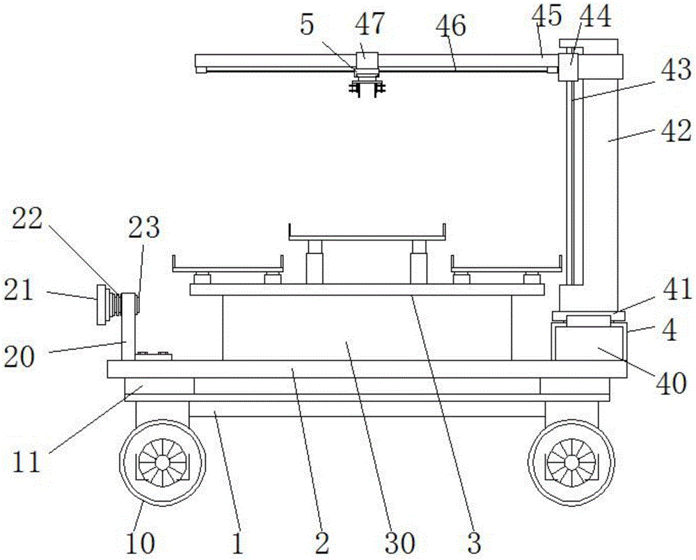
Fig. 1 is a schematic front view of an embodiment of the present invention;
fig. 2 is a left side view of the embodiment of the present invention;
fig. 3 is a schematic top view of a placement table according to an embodiment of the present invention;
fig. 4 is a schematic view of a hanger mounting according to an embodiment of the present invention;
fig. 5 is a schematic view of a lower structure of the hanger according to an embodiment of the present invention.
In the figure: 1. a base; 10. a roller; 11. a connecting plate; 2. a trolley; 20. a front fixing plate; 21. head collision prevention; 22. a spring; 23. mounting a rod; 3. a placing table; 30. a support plate; 31. a top plate; 32. a first storage frame; 33. a second storage frame; 34. a third storage frame; 35. a second telescopic cylinder; 4. a rear mounting seat; 40. a motor; 41. a turntable; 42. erecting; 43. a Z-axis linear slide rail; 44. a first slider; 45. a cross frame; 46. an X-axis linear slide rail; 47. a second slider; 5. a hanger; 50. a Y-axis linear slide rail; 51. a third slider; 52. an upper fixing plate; 53. a first telescopic cylinder; 54. an outer panel; 55. an inner side plate; 56. and (4) clamping the plate.
Detailed Description
The following description of the embodiments of the present invention is provided for illustrative purposes, and other advantages and effects of the present invention will be readily apparent to those skilled in the art from the disclosure herein. The present invention can also be implemented or applied through other different specific embodiments, and various details in the present specification can be modified or changed based on different viewpoints and applications without departing from the spirit of the present invention.
Fig. 1 is the utility model discloses front view schematic diagram, fig. 2 are the utility model discloses a left side view schematic diagram, fig. 3 do the utility model discloses a settling platform overlook the schematic diagram, fig. 4 does the utility model discloses a gallows installation schematic diagram and fig. 5 are the utility model discloses a structure sets up the schematic diagram under the gallows.
Referring to fig. 1-5, the utility model provides a material dolly is got to intelligence beverage drinks vending machine, include: the device comprises a base 1, a mounting platform 3, a rear mounting seat 4 and a hanging bracket 5; the base 1 is arranged on the lower end face of the trolley 2, a group of connecting plates 11 are fixed at four corners of the upper end face of the base 1, the upper ends of the connecting plates 11 are fixed on the lower end face of the trolley 2, and a group of rollers 10 are arranged at the left end and the right end of the front part and the rear part of the base 1; the placing table 3 is arranged in the middle of the upper end face of the trolley 2; the rear mounting seat 4 is mounted at the rear part of the upper end face of the trolley 2, a vertical frame 42 is arranged at the rear part of the rear mounting seat 4, a first sliding block 44 is movably arranged on the vertical frame 42, a transverse frame 45 is fixed at the front end of the first sliding block 44, and a second sliding block 47 is movably arranged on the transverse frame 45; the hanger 5 is mounted on the lower end surface of the second slider 47.
In this embodiment, a front fixing plate 20 is disposed in front of the upper end surface of the cart 2, four sets of mounting rods 23 are mounted on the upper portion of the front fixing plate 20, a collision-proof head 21 is mounted at the front end of the mounting rods 23, the collision-proof head 21 is made of soft rubber, and a spring 22 is sleeved on the middle rod body of the mounting rods 23.
As a preferred embodiment, the utility model discloses a dolly 2 is gone up the front end and is provided with preceding fixed plate 20, installs multiunit on the preceding fixed plate 20 and prevents bumping head 21 to utilize to prevent bumping head 21 and carry out the elastic shock attenuation, reduce the collision impact force that comes from the place ahead, so that the dolly leads to falling the thing because of receiving to strike too big emergence and rock.
In this embodiment, the installation table 3 is provided with a top plate 31, a support plate 30 is fixed between the lower end surface of the top plate 31 and the upper end surface of the trolley 2, a first storage frame 32, a second storage frame 33 and a third storage frame 34 are sequentially installed above the top plate 31 from front to back, and four sets of second telescopic cylinders 35 are installed between the first storage frame 32, the second storage frame 33 and the third storage frame 34 and the top plate 31.
As an embodiment of preferred, the utility model discloses the top of the roof 31 of well arrangement platform 3 is provided with first thing frame 32, the second puts thing frame 33 and the third puts thing frame 34, and three groups put the thing frame height difference, conveniently classify and place the material, and convenient to use is nimble.
In this embodiment, the motor 40 is installed in the bottom of the rear mounting seat 4, the upper end of the rotating shaft at the upper end of the motor 40 is fixed at the center of the rotating disc 41, the lower end of the vertical frame 42 is fixed at the center of the upper end face of the rotating disc 41, the first slide block 44 is slidably connected to the Z-axis linear slide rail 43 at the front side face of the vertical frame 42, and the second slide block 47 is slidably connected to the X-axis linear slide rail 46 at the lower end face of the horizontal frame 45.
As a preferred embodiment, the first slider 44 and the Z-axis linear slide rail 43, the second slider 47 and the X-axis linear slide rail 46 of the present invention are connected in a sliding manner, so as to conveniently drive the hanging bracket 5 to move in the direction of the Z, X axes.
In the present embodiment, a Y-axis linear slide rail 50 is disposed in the lower end surface of the hanger 5, a third slider 51 is slidably connected to the Y-axis linear slide rail 50, and an upper fixing plate 52 is fixed to the lower end of the third slider 51; the front and rear parts of the lower end surface of the upper fixing plate 52 are provided with an outer side plate 54 and an inner side plate 55, the outer side plate 54 is positioned outside the inner side plate 55, and a plurality of sets of first telescopic cylinders 53 are installed between the outer side plate 54 and the inner side plate 55, and the front ends of the first telescopic cylinders 53 are fixed on the rear side surface of a clamping plate 56.
As an embodiment of preferred, the utility model provides a third slider 51 sliding connection is in Y axle linear slide 50 in gallows 5 to drive the removal activity of upper fixed plate 52 in Y axle side, be fixed with telescopic cylinder between the first telescopic cylinder 53 that sets up under upper fixed plate 52 and the outer panel 54, the telescopic cylinder who utilizes both sides around, promotes the splint activity, conveniently carries out the centre gripping material, and places the material in putting the thing frame, and it is more convenient to use to save trouble.
The utility model discloses can effectively solve prior art's the material dolly of getting and not make things convenient for the automatic clamp to get the material and place above that, use and be difficult to satisfy the user demand that intelligence was sold goods today, use and the convenient problem of intelligence, the utility model discloses the structure sets up rationally, conveniently utilizes the clamp to get the mechanism and carry out the migration activity on X, Y, Z axles to in the material is got and the thing frame of putting on placing the dolly is got in a flexible way to the clamp, use more nimble trouble-saving.