Floor bearing plate adopting sheet type double-layer steel bar truss
Technical Field
The utility model belongs to the technical field of the building element to heat, sound or the isolation of noise, absorption or reflection, specifically disclose an adopt double-deck steel bar truss's of piece formula building carrier plate.
Background
In the process of building and constructing the floor slab, the prior construction procedures are as follows: the fixed laminated slab → the binding steel bar → the concrete layer is poured, and in the process of pouring the concrete layer, a heat preservation and sound insulation material layer is laid according to the heat preservation and sound insulation requirements of the floor slab. In order to enable the floor slab construction site construction to be more convenient and faster, the construction period is faster, a prefabricated floor bearing plate can be used when the floor slab is constructed at present, after the floor bearing plate is fixed in site construction, reinforcing steel bars are fixed and bound on the floor bearing plate, concrete is poured, and the floor slab can be formed after the concrete is solidified.
Building carrier plate is when production, in order to guarantee its atress intensity, can lay the reinforcing bar net in the building carrier plate, and the building carrier plate ligature reinforcing bar when for the convenience of follow-up use can be fixed steel bar truss on the building carrier plate in advance. At present steel bar truss adopts many vertical reinforcing bars, adopts steel bar welded connection as an organic whole between a plurality of vertical reinforcing bars, and the atress intensity of guarantee building carrier plate that this kind of steel bar truss can be better when using.
Through the intensive research of the applicant, the steel bar truss and the floor bearing plate can be stably connected by embedding the part of the steel bar truss into the floor bearing plate. However, the steel bar mesh is required to be laid on the floor support plate, a plurality of steel bar trusses are embedded, the amount of used steel bars is large, the cost of the steel bars is high, and the cost of the floor support plate is high due to the large amount of used steel bars. Lay the reinforcing bar net in addition, pre-buried a plurality of steel bar trusses also will make the production process of floor carrier plate hard, complicated. In addition, during floor construction, a plurality of double-layer steel bars are needed on the template, so that the floor construction is complex.
Disclosure of Invention
An object of the utility model is to provide an adopt double-deck steel bar truss's of piece formula building carrier plate to in solving present building carrier plate, the reinforcing bar quantity is more, use loaded down with trivial details problem.
In order to achieve the above object, the basic scheme of the utility model is: the utility model provides an adopt floor carrier plate of double-deck steel bar truss of piece formula, includes template and a plurality of truss, the truss is including last chord reinforcing bar, upper reinforcing bar, the last chord reinforcing bar and a plurality of connecting piece that are located same vertical plane, last chord reinforcing bar and last chord reinforcing bar pass through connecting piece fixed connection, upper reinforcing bar is located between last chord reinforcing bar and the last chord reinforcing bar and is fixed with the connecting piece, outside the upper portion of last chord reinforcing bar, upper reinforcing bar and connecting piece of truss stretched out the template, was connected with horizontal muscle down between the last chord reinforcing bar of a plurality of trusss.
When the construction site uses the floor support plate, double-layer bidirectional steel bars need to be laid on the template, and the part of the truss positioned on the template in the scheme is of a double-layer structure, namely a sheet type double-layer truss, so that the step of laying the double-layer bidirectional steel bars needed by using the template on the construction site is reduced.
The working principle of the basic scheme is as follows: during the production of the building carrier plate in this scheme, adopt quantity to be fit for a plurality of trusses according to the width of building carrier plate, with truss interval align to grid and vertical the placing, set up a plurality of horizontal muscle down and fixed on last chord steel bar down, form truss overall structure. And then pouring the template, putting the assembled truss integral structure into the template, paying attention to the fact that the upper part of the connecting piece, the upper chord steel bars and the upper layer steel bars are exposed out of the template, and the lower part of the connecting piece and the lower chord steel bars are sunk into the floor bearing plate. When the floor support plate is used, the template is fixed above the beam or the wall body, and the template can be transported and hoisted by adopting equipment through upper chord steel bars; and after the template is fixed, binding reinforcing steel bars on the upper-layer reinforcing steel bars and the upper-chord reinforcing steel bars, and then pouring concrete to form the floor slab by the template and the newly poured concrete layer.
The beneficial effect of this basic scheme lies in:
1. the truss in this building carrier plate is double-deck truss, compares to steel bar truss in the past, and simple structure is used in on the building carrier plate because last chord reinforcing bar, upper reinforcing bar, last chord reinforcing bar and connecting piece are located the coplanar, can fully bear the longitudinal force of floor, satisfies the demand of this building carrier plate's atress intensity.
2. This building carrier plate is when production, in advance with a plurality of trusss, fixed as an organic whole through horizontal muscle down, horizontal muscle down and last chord steel bar have just formed the rigidity net, then need not to lay the rigidity net in the template, have further reduced the reinforcing bar quantity of this building carrier plate, can also make the truss can be firm bury this template in, make the stress intensity reinforcing of this building carrier plate.
3. This building carrier plate is when production, and is as an organic whole with a plurality of truss welding through horizontal muscle down, makes the building carrier plate pour the in-process and need not to lay the reinforcing bar net, also need not to put into a plurality of steel bar trusses, and this process of having saved the production of building carrier plate greatly has improved the production efficiency of building carrier plate.
4. The lower parts of the lower transverse bar, the lower chord steel bar and the connecting piece in the floor bearing plate are positioned in the template, after the floor construction is completed, the upper chord steel bar and the upper part of the connecting piece are embedded into a cast-in-place concrete layer, and the floor bearing plate is prevented from being separated from the concrete layer in the subsequent long-term use process of the floor.
Compared with the prior art, this building carrier plate can save the reinforcing bar quantity greatly under the prerequisite that satisfies the atress intensity, can also reduce the production processes of building carrier plate, and when the floor concreting, need use bilayer structure reinforcing bar, last chord steel bar and the upper reinforcing bar on the truss can satisfy the requirement simultaneously.
Furthermore, the upper chord steel bar, the upper layer steel bar and the lower chord steel bar are arranged in parallel, and the connecting piece is arranged obliquely to the upper chord steel bar.
Has the advantages that: the upper chord steel bar, the upper layer steel bar and the lower chord steel bar are arranged in parallel, so that the integral structure of the truss in the scheme looks more attractive, and the floor support plate has stronger bearing capacity after being used. The connecting piece is connected between the upper chord steel bar and the lower chord steel bar and used for bearing the tensile force of the upper chord steel bar and the lower chord steel bar, the connecting piece is arranged obliquely with the upper chord steel bar, and the stress can be dispersed, so that the bearing strength is higher.
Furthermore, the connecting piece includes first connecting piece and second connecting piece, and first connecting piece and second connecting piece set up along different angles slope in last chord reinforcing bar, and the connecting piece both ends weld respectively on last chord reinforcing bar and last chord reinforcing bar.
Has the advantages that: the connecting piece sets up like this and can makes its atress disperse along a plurality of directions, and then makes the atress intensity reinforcing of truss, and the connecting piece both ends weld respectively on last quarter reinforcing bar and last quarter reinforcing bar, can make the truss in this scheme be the integral type structure, and whole comparatively firm.
Furthermore, the first connecting piece and the second connecting piece are arranged in a splayed shape or a herringbone shape.
Has the advantages that: the first connecting piece and the second connecting piece are arranged in a splayed shape, so that two ends of the first connecting piece and two ends of the second connecting piece are fixedly connected with the upper chord steel bar and the lower chord steel bar conveniently. The first connecting piece and the second connecting piece are arranged in a herringbone mode, the position occupied by one connecting piece is narrow, the connecting pieces in one truss can be sequentially arranged, and the stress strength between the upper chord steel bar and the lower chord steel bar is enhanced.
Further, the template sequentially comprises a top plate, a heat preservation and sound insulation layer and a bottom plate from top to bottom, and the lower part of the truss is positioned in the top plate; the bottom plate is internally provided with a bottom plate rigid net which comprises transverse steel bars and longitudinal steel bars, and the transverse steel bars are bent upwards and then penetrate through the heat preservation and sound insulation layer and the top plate to form a reinforcing piece.
Has the advantages that: the floor bearing plate has the functions of heat preservation and sound insulation, and has the effects of heat preservation and sound insulation between floors when being used for building the floor. The bottom plate rigid net can enhance the stress strength of the floor bearing plate, and the reinforcing piece can firmly connect the bottom plate, the heat-preservation sound-insulation layer and the top plate together.
Furthermore, an upper transverse bar is connected between the upper chord steel bars of the trusses, and the upper transverse bar is positioned between the two lower transverse bars in the horizontal direction.
Has the advantages that: in the manufacturing process of the floor bearing plate, a plurality of trusses are connected into a whole through the lower transverse ribs and then are placed into the template to form the floor bearing plate; in the process, the lower chord steel bar can be in a fixed position under the connecting action of the lower transverse bar and the action of the template; however, since the truss is of a sheet structure, the connecting piece and the upper chord steel bar of the truss are located on the same vertical plane, the upper chord steel bar and the connecting piece are easy to deviate from the original vertical plane, and the stress condition of a single truss can be influenced after deviation. The upper chord reinforcements of the trusses can be fixedly connected through the upper transverse reinforcements, so that the upper chord reinforcements and the connecting pieces on one truss are prevented from deviating from a vertical plane, the truss is always in the vertical plane, and the stress of the floor bearing plate is always kept in an ideal state in the using process. Meanwhile, when the floor support plate is hoisted, the joint of the upper transverse bar and the upper chord steel bar can be selected as a hoisting point for hoisting, and the situation that the truss is damaged due to uneven stress and bending of the upper chord steel bar only when the upper chord steel bar is hoisted is avoided. In addition, the lower transverse ribs connect the lower chord steel bars of the trusses, the upper transverse ribs connect the upper chord steel bars of the trusses, the trusses are connected into a steel reinforcement cage with a three-dimensional structure through the upper transverse ribs and the lower transverse ribs, the steel reinforcement cage serves as a part of the floor bearing plate, the self stress strength or the stress strength of the floor after construction is uniformly dispersed, and the stress effect is good.
Furthermore, the part of the reinforcing piece above the top plate is bent, the bent part of the reinforcing piece is positioned below the upper chord steel bar, and a damping sleeve is arranged outside the reinforcing piece.
Has the advantages that: the reinforcement is bent to enable the upper part of the reinforcement to play a role of a hook, namely, the connection strength of the poured concrete layer and the floor bearing plate is stronger through the upper part of the reinforcement; compared with the reinforcing piece buried in the top plate, the reinforcing piece extends out of the top plate, so that construction is easier, and the floor support plate is less prone to cracking when in use; the damping cover can reduce the transmission of sound in the floor bearing plate.
Furthermore, the bending part of the reinforcing piece and the reinforcing piece are arranged at an angle of less than or equal to 90 degrees.
Has the advantages that: the kink so sets up when this floor carrier plate of being convenient for uses, and it is better, safer to hang power.
Further, the transverse steel bars on the bottom plate rigid net are positioned below the longitudinal steel bars, and the lower transverse steel bars are positioned above the lower chord steel bars.
Has the advantages that: the transverse steel bars on the bottom plate rigid net are bent upwards to form the reinforcing piece, a part of longitudinal acting force can be borne, the reinforcing piece is arranged below the longitudinal steel bars, and under the matching of the longitudinal steel bars, the stress action can be better. The lower chord steel bar bears upward pulling force and is arranged below the lower transverse bar, and the stress action is enhanced.
Further, the heat preservation and sound insulation layer is made of porous materials, a plurality of cavities are arranged between the bottom plate and the heat preservation and sound insulation layer, and the cavities are hole grooves formed in the upper surface of the bottom plate.
Has the advantages that: the porous perforated material is a material with a large number of small gaps and holes which are communicated with each other inside and outside, when sound waves are transmitted into the heat-insulation and sound-insulation layer, the sound waves enter the material along the holes to cause the vibration of air in the holes, most sound energy is converted into heat energy to be consumed due to the effects of viscous resistance, heat conduction and the like of the air, and therefore most medium-high frequency sound waves in the sound waves are eliminated by the heat-insulation and sound-insulation layer made of the porous perforated material. When sound passes through the heat-insulating and sound-insulating layer and then weakens medium-high frequency sound, and when the sound enters the cavity again, the sound waves cause air vibration in the cavity, so that most sound energy is converted into heat energy to be consumed, and a better silencing effect is achieved. The cavity is a hole groove formed in the upper surface of the bottom plate, so that sound waves are subjected to multiple diffuse reflection on the wall of the hole groove of the bottom plate, multiple conversion and consumption of sound energy are realized, and the silencing effect is further enhanced.
Drawings
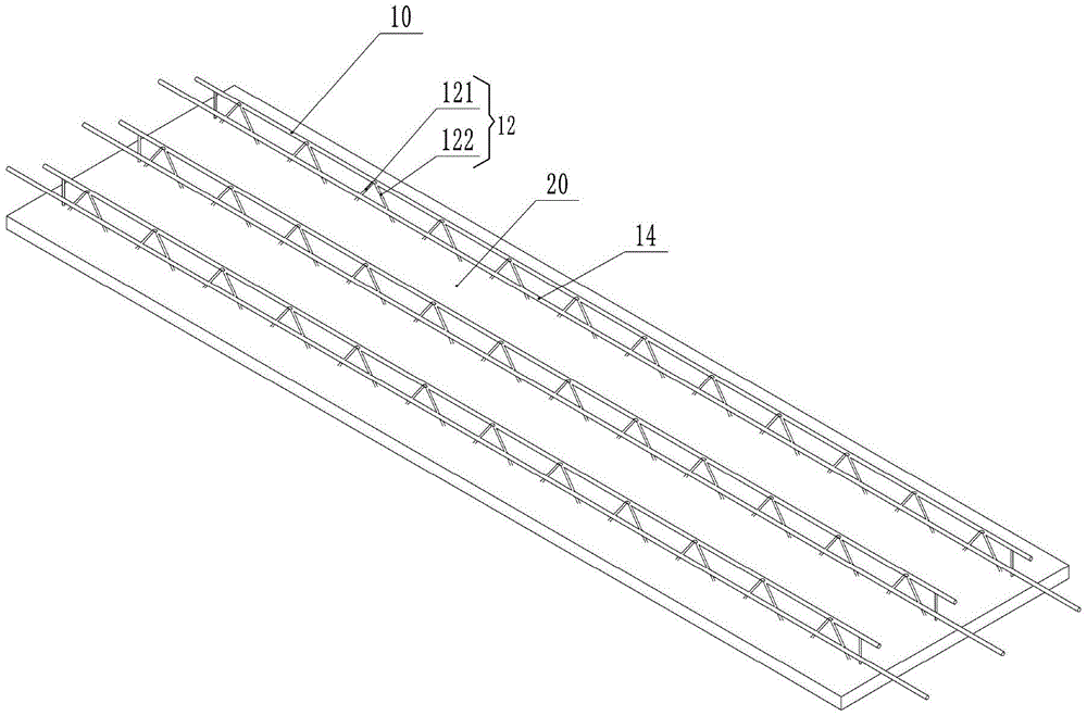
Fig. 1 is a schematic structural diagram of a floor deck in an embodiment 1 of the present disclosure;
fig. 2 is a schematic structural diagram of a floor deck embodiment 2 in the scheme;
fig. 3 is a schematic structural diagram of a floor deck embodiment 3 in the scheme;
fig. 4 is a schematic structural diagram of a floor deck embodiment 4 in the present solution;
fig. 5 is a schematic structural diagram of a floor deck embodiment 5 in the present solution;
fig. 6 is a schematic structural diagram of a floor deck embodiment 6 in the present solution;
figure 7 is a longitudinal cross-sectional view of a deck embodiment 6 of the present solution;
figure 8 is a transverse cross-sectional view of the deck embodiment 6 of the present solution;
figure 9 is a transverse cross-sectional view of the deck embodiment 7 of the present solution;
figure 10 is a transverse cross-sectional view of the deck embodiment 8 of the present solution;
fig. 11 is a schematic structural view of a floor deck embodiment 9 in the present solution;
figure 12 is a longitudinal cross-sectional view of the deck embodiment 9 of the present solution.
Detailed Description
The following is further detailed by way of specific embodiments:
reference numerals in the drawings of the specification include: the steel bar comprises an upper chord steel bar 10, a lower chord steel bar 11, a connecting piece 12, a first connecting piece 121, a second connecting piece 122, a connecting steel bar 13, an upper layer steel bar 14, a template 20, a lower transverse bar 21, a side connecting table 22, an end connecting table 23, an upper transverse bar 24, a top plate 30, a heat-preservation sound-insulation layer 31, a bottom plate 32, a bottom plate rigid net 33, a reinforcing piece 34 and a damping sleeve 341.
Example 1
As shown in fig. 1, a floor support plate 20 using a sheet-type double-layer steel bar truss includes a formwork 20 and a plurality of trusses, where the trusses include upper-chord steel bars 10, upper-layer steel bars 14, lower-chord steel bars 11 (as shown in fig. 8) and a plurality of connecting members 12 located on the same vertical plane, and in actual production, for convenience of construction, the upper-chord steel bars, the upper-layer steel bars 14, the lower-chord steel bars 11 and the plurality of connecting members 12 may be arranged in a staggered manner, the upper-chord steel bars 10 and the lower-chord steel bars 11 are fixedly connected by the connecting members 12, the upper portions of the trusses extend out of the formwork 20, and lower transverse bars 21 (as shown in fig. 8) are connected between the lower-chord steel bars 11 of the plurality of trusses. In this embodiment, three trusses are used for one formwork 20, and the three trusses are uniformly arranged at intervals along the width direction of the formwork 20.
The upper chord steel bars 10 and the upper layer steel bars 14 are arranged in parallel with the lower chord steel bars 11, the upper chord steel bars 10, the upper layer steel bars 14 and the lower chord steel bars 11 are parallel to the upper surface of the formwork 20, and when the formwork 20 is placed horizontally, the upper chord steel bars 10, the upper layer steel bars 14 and the lower chord steel bars 11 are located at horizontal positions. The connecting pieces 12 are arranged obliquely to the upper chord steel bars 10, and the interval distances between the adjacent connecting pieces 12 are the same; the connecting member 12 in this embodiment includes a first connecting member 121 and a second connecting member 122, and the first connecting member 121 and the second connecting member 122 are disposed at different angles to the upper chord rebar 10. In order to ensure the stress strength of the connecting members 12, the first connecting member 121 and the second connecting member 122 are arranged in a shape like a Chinese character 'ren', the spacing distance between adjacent connecting members 12 is 0-50cm, and in this embodiment, the distance between adjacent connecting members 12 is preferably 0.
In order to facilitate the manufacture of the truss in the scheme, two ends of the connecting piece 12 are respectively welded on the upper chord steel bar 10 and the lower chord steel bar 11, the length direction of the truss is located at the tail end of the connecting piece 12, and the connecting steel bar 13 perpendicular to the upper chord steel bar 10 and the lower chord steel bar 11 is welded. The upper chord steel bar 10 and the lower chord steel bar 11 in the truss adopt common anti-seismic screw steel in the market, and the connecting piece 12 is made of steel materials. According to the stress conditions of the upper chord steel bar 10, the lower chord steel bar 11 and the connecting piece 12 in the using process, the diameter of the connecting piece 12 is smaller than the diameters of the upper chord steel bar 10 and the lower chord steel bar 11, and the diameter of the lower chord steel bar 11 is smaller than the diameter of the upper chord steel bar 10.
The specific implementation process is as follows: in this embodiment, the floor support plate 20 is produced by placing four trusses at first, uniformly arranging the trusses at intervals, vertically placing the trusses, horizontally erecting a plurality of lower transverse ribs 21 on the lower chord steel bars 11, and welding and fixing the lower transverse ribs 21 and the lower chord steel bars 11 to form an integral truss structure. When the floor support plate 20 in this embodiment is produced, the formwork 20 is poured, then the assembled truss overall structure is placed into the formwork 20, it is noticed that the upper portion of the connecting member 12, the upper-layer reinforcing steel bars 14 and the upper-chord reinforcing steel bars 10 are exposed out of the floor support plate 20, and the lower portion of the connecting member 12 and the lower-chord reinforcing steel bars 11 are sunk into the formwork, so that the production and manufacturing of the floor support plate 20 in this embodiment can be completed.
When building carrier plate 20 in this scheme uses, adopt equipment to transport and hoist this building carrier plate 20 through last string reinforcing bar 10, after building carrier plate 20 is fixed, ligature reinforcing bar or place the reinforcing bar net piece on last string reinforcing bar 10, then carry out concrete placement, building carrier plate 20 and the concrete layer of newly-pouring form the floor.
Example 2
The difference between this embodiment and embodiment 1 is that, as shown in fig. 2, in this embodiment, the first connecting member 121 and the second connecting member 122 are arranged in a "eight" shape, the spacing distance between adjacent connecting members 12 and the shortest spacing distance between the first connecting member 121 and the second connecting member 122 are 10-50cm, and in this embodiment, the spacing distance between adjacent connecting members 12 and the shortest spacing distance between the first connecting member 121 and the second connecting member 122 are equal.
By adopting the splayed connecting pieces 12, a certain distance exists between the first connecting piece 121 and the second connecting piece 122, so that the number of the connecting pieces 12 used by the truss is reduced, and the number of steel bars used by the whole truss is reduced.
Example 3
The present embodiment is different from embodiment 1 in that side connection stages 22 are provided at both sides of the lower end surface of the floor deck 20 as shown in fig. 3.
The arrangement of the side connecting table 22 is convenient for supporting the splicing part after the templates 20 are spliced with each other when the floor support plate 20 is used in the embodiment, so that the floor support plate 20 is fixed in the embodiment.
Example 4
The present embodiment is different from embodiment 3 in that, as shown in fig. 4, the formwork 20 in the present embodiment includes a top plate 30, a heat insulating and sound insulating layer 31, and a bottom plate 32 in sequence from top to bottom, and the lower portion of the truss is located in the top plate 30. In this embodiment, the thermal insulation and sound insulation layer 31 is made of porous open-cell material, that is, the porous open-cell material has a large number of micro gaps and pores which are communicated with each other inside and outside, and the thermal insulation and sound insulation layer 31 is made of rock wool in this embodiment. A concave-convex cavity is formed between the bottom plate 32 and the heat preservation and sound insulation layer 31, specifically, a hole groove can be arranged on the upper surface of the bottom plate 32, a hole groove can also be arranged on the lower surface of the heat preservation and sound insulation layer 31, and hole grooves can also be arranged on the upper surface of the bottom plate 32 and the lower surface of the heat preservation and sound insulation layer 31 simultaneously. The shape of the pore groove can be wave-shaped, zigzag, honeycomb-shaped, pulse-shaped or other irregular shapes and the like. Shock-absorbing pads are paved in the top plate 30 or between the top plate 30 and the heat-preservation sound-insulation layer 31, and also can be paved in the top plate 30 and between the top plate 30 and the heat-preservation sound-insulation layer 31, and the shock-absorbing pads can be made of materials which can play a role of buffering and shock-absorbing, such as pearl cotton, bubble films and the like. The bottom plate 32 is laid with a bottom plate rigid net 33, in this embodiment, the bottom plate rigid net 33 is made of rigid materials such as steel wires, steel bars, iron wires, and the like, and is formed by welding the same kind of materials or different kinds of materials in a criss-cross manner. In this embodiment, the rigid net 33 of the bottom plate is formed by a plurality of transverse steel bars and a plurality of longitudinal steel bars which are staggered to form a net structure.
Since the sound is transmitted by the impact or vibration generated from the floor between the upper and lower floors, the form 20 in this embodiment attenuates the transmission of the sound by taking measures. Namely, when the impact vibration is transmitted to the shock pad on the top plate 30, the vibration force is buffered and weakened on the shock pad, so that the high-frequency sound wave generated by the vibration is simultaneously weakened, the weakened sound wave enters the heat insulation and sound insulation layer 31 of the porous open-cell material, enters the material along the holes communicated with the inside and the outside of the porous open-cell material to cause the vibration of the air in the holes, and most sound energy is converted into heat energy to be consumed due to the viscous resistance, the heat conduction and other effects of the air, so that most medium-frequency and high-frequency sound waves in the sound wave are further eliminated. Finally, when sound waves pass through the heat-insulation sound-insulation layer 31 and enter the hole grooves in the bottom plate 32, the sound waves form multiple diffuse reflection on the uneven hole groove walls, so that sound energy of medium and low frequencies is converted and consumed, and the sound-attenuation and sound-insulation effects are better played.
Example 5
The present embodiment is different from embodiment 4 in that, as shown in fig. 5, end connection platforms 23 are provided at both ends of the lower end surface of the floor deck 20, and the heat and sound insulation layer 31 and the bottom plate 32 are not provided at the end connection platforms 23.
Example 6
The difference between this embodiment and embodiment 4 is that, as shown in fig. 6, 7 and 8, the transverse steel bars of the bottom plate rigid net 33 are bent upwards to pass through the heat and sound insulation layer 31 and the top plate 30 to form a reinforcing member 34; in this embodiment, the part of the reinforcing member 34 above the top plate 30 is bent, the bent part of the reinforcing member 34 is located below the upper chord steel bar 10 and above the upper layer steel bar 14, and the damping sleeve 341 is disposed outside the reinforcing member 34.
The reinforcing member 34 extending out of the top plate 30 is convenient for construction on one hand, and after the floor slab is constructed on the other hand, the reinforcing member 34 penetrates through the formwork 20 and the floor slab, so that the hoisting of the formwork 20 is not easy to crack; furthermore, the bent portions of the reinforcing members 34 facilitate the binding of reinforcing bars during the construction of the floor.
Example 7
The present embodiment is different from embodiment 5 in that, as shown in fig. 9, the bent portion of the reinforcing member 34 is disposed perpendicular to the reinforcing member 34 in the present embodiment.
Example 8
The difference between this embodiment and embodiment 5 is that, as shown in fig. 10, the bent portion of the reinforcing member 34 and the reinforcing member 34 in this embodiment form an included angle structure smaller than 90 °, and the bent portion of the reinforcing member 34 is inclined toward the lower form 20.
Example 9
The present embodiment is different from embodiment 6 in that, as shown in fig. 11 and 12, an upper transverse bar 24 is connected between the upper chord steel bars 10 of the plurality of trusses in the present embodiment, and the upper transverse bar 24 is located between two lower transverse bars in the horizontal direction; in order to make the upper transverse bar 24 more stressed, the upper transverse bar 24 is also positioned at the midpoint between the first connecting member 121 and the second connecting member 122.
The setting of middle-upper horizontal muscle 24 in this embodiment can make every truss all keep vertical state, and all trusses form the structure of steel reinforcement cage under the effect of last horizontal muscle 24 and horizontal muscle 21 down, and then make the whole atress performance of truss better. When the floor support plate in the embodiment is hoisted, the joint of the upper transverse rib 24 and the upper chord steel bar 10 can be selected as a hoisting point, the stress intensity is better when the steel bars are concentrated, and the floor support plate can be prevented from being damaged due to hoisting. The upper transverse rib 24 and the lower transverse rib 21 are arranged in a staggered mode, so that the stress strength of the whole truss in all directions is balanced, and the influence caused by the weak stress strength of a certain part in the use process of the floor bearing plate is avoided.
The above description is only an example of the present invention, and the detailed technical solutions and/or characteristics known in the solutions are not described too much here. It should be noted that, for those skilled in the art, without departing from the technical solution of the present invention, several modifications and improvements can be made, which should also be regarded as the protection scope of the present invention, and these will not affect the effect of the implementation of the present invention and the practicability of the patent. The scope of the claims of the present application shall be defined by the claims, and the description of the embodiments and the like in the specification shall be used to explain the contents of the claims.