CN216586185U - A double-layer Bailey beam hoisting structure - Google Patents
A double-layer Bailey beam hoisting structure Download PDFInfo
- Publication number
- CN216586185U CN216586185U CN202122845743.7U CN202122845743U CN216586185U CN 216586185 U CN216586185 U CN 216586185U CN 202122845743 U CN202122845743 U CN 202122845743U CN 216586185 U CN216586185 U CN 216586185U
- Authority
- CN
- China
- Prior art keywords
- double
- bailey
- layer
- hoist
- shackle
- Prior art date
- Legal status (The legal status is an assumption and is not a legal conclusion. Google has not performed a legal analysis and makes no representation as to the accuracy of the status listed.)
- Active
Links
Images



Landscapes
- Load-Engaging Elements For Cranes (AREA)
Abstract
本实用新型属于支架现浇梁贝雷架吊装技术领域,解决了现有贝雷梁吊装结构中,吊装工序复杂、钢丝绳解绑困难、易磨损造成安全隐患的问题。提供了一种双层贝雷梁吊装结构,包括双层贝雷梁,双层贝雷梁由两道并排设置的贝雷架单元拼接而成,贝雷架包括上弦杆、下弦杆和连接在两者之间的腹杆,上弦杆包括两道相连接的槽钢梁;双层贝雷梁上靠近左右两侧的位置各设置有一组吊具,吊具的截面为山字形,上弦杆的两道槽钢梁的底部分别卡接在吊具的两个托槽中,吊具的上端伸出上弦杆,且连接有卸扣,卸扣上连接有钢丝绳,同一组吊具对应的两个钢丝绳连接在同一起吊装置的吊钩上。本实用新型结构简单、拆装便捷、稳定性高,避免了在吊装时出现脱钩的隐患。
The utility model belongs to the technical field of the hoisting of the cast-in-place beam Bailey frame of the bracket, and solves the problems of the existing Bailey beam hoisting structure that the hoisting procedure is complicated, the wire rope is difficult to untie, and the safety hazards are caused by easy wear and tear. Provided is a double-layer Bailey beam hoisting structure, including a double-layer Bailey beam, the double-layer Bailey beam is formed by splicing two Bailey frame units arranged side by side, and the Bailey frame includes an upper chord, a lower chord and a The web bar and the upper chord between the two consist of two connected channel steel beams; a set of spreaders are arranged on the double-layer Bailey beams near the left and right sides. The bottoms of the two channel steel beams are respectively clamped in the two brackets of the spreader, the upper end of the spreader protrudes from the upper chord, and is connected with a shackle, and a wire rope is connected to the shackle. The wire rope is connected to the hook of the same hoisting device. The utility model has the advantages of simple structure, convenient disassembly and assembly, high stability, and avoids the hidden danger of decoupling during hoisting.
Description
技术领域technical field
本实用新型属于支架现浇梁贝雷架吊装技术领域,具体涉及一种双层贝雷梁吊装结构。The utility model belongs to the technical field of hoisting a cast-in-place beam Bailey frame of a bracket, and particularly relates to a double-layer Bailey beam hoisting structure.
背景技术Background technique
铁路桥梁作为交通设施的重要组成部分,支架现浇简支梁和支架现浇连续梁大多采用贝雷架,贝雷架可在跨越河道、道路时满足现场施工。As an important part of transportation facilities, railway bridges are mostly cast-in-place simply supported beams and continuous cast-in-place beams with berets, which can meet on-site construction when crossing rivers and roads.
在贝雷架吊装时,一般采用钢丝绳兜吊,钢丝绳在吊装贝雷架前,需要对贝雷架进行捆绑,在吊装完成后需要将钢丝绳从贝雷架上解绑,工序复杂,比较浪费时间,而且钢丝绳受力后常常缠绕紧固一起不好拆卸,在钢丝绳与贝雷架接触部位容易磨损钢丝绳造成安全隐患,是贝雷架吊装时的一大的难题。When the beret is hoisted, the steel wire rope is generally used for hoisting. The steel wire rope needs to be tied to the beret before hoisting the beret. After the hoisting is completed, the wire rope needs to be unbound from the beret. The process is complicated and time consuming. , and the wire rope is often twisted and tightened together after being stressed, and it is not easy to disassemble, and the wire rope is easily worn at the contact part between the wire rope and the beret frame, causing potential safety hazards, which is a major problem when hoisting the beray frame.
因此,一种能够快速装卸、且避免脱钩隐患的双层贝雷梁吊装结构亟待研究。Therefore, a double-layer Bailey beam hoisting structure that can be quickly loaded and unloaded and avoid the hidden danger of decoupling needs to be studied urgently.
实用新型内容Utility model content
针对现有贝雷梁吊装结构中,吊装工序复杂、钢丝绳解绑困难、易磨损造成安全隐患的不足,本实用新型的目的在于提供一种双层贝雷梁吊装结构,在双层贝雷梁左右两侧上弦杆上设置有两组吊具,上弦杆的槽钢梁卡在吊具的托槽中,将双层贝雷梁稳稳托起,拆装时,只需将吊具下降或上升一段位置,再转动90度提升,即可完成拆卸和安装。Aiming at the shortcomings of the existing Bailey beam hoisting structure, the hoisting process is complicated, the wire rope is difficult to untie, and easy to wear, causing potential safety hazards. There are two sets of spreaders on the left and right upper chords. The channel steel beams of the upper chord are stuck in the brackets of the spreaders, and the double-layer Bailey beams are stably held up. When disassembling and assembling, only the spreaders need to be lowered or raised a section. position, and then turn it 90 degrees to lift to complete the disassembly and installation.
为实现上述目的,本实用新型采用如下技术方案,一种双层贝雷梁吊装结构,包括双层贝雷梁,双层贝雷梁由两道并排设置的贝雷架单元拼接而成,贝雷架单元包括多个依次连接的贝雷架,贝雷架包括上弦杆、下弦杆和连接在两者之间的腹杆,上弦杆包括两道相连接的槽钢梁;双层贝雷梁上靠近左右两侧的位置各设置有一组吊具,每组吊具为两个,分别设置在前后相对的两个上弦杆上,吊具的截面为山字形,上弦杆的两道槽钢梁的底部分别卡接在吊具的两个托槽中,吊具的上端伸出上弦杆,且连接有卸扣,卸扣上连接有钢丝绳,同一组吊具对应的两个钢丝绳连接在同一起吊装置的吊钩上。In order to achieve the above-mentioned purpose, the present utility model adopts the following technical scheme, a double-layer Bailey beam hoisting structure, comprising a double-layer Bailey beam, the double-layer Bailey beam is formed by splicing two Bailey frame units arranged side by side, and the double-layer Bailey beam is spliced together. The mine frame unit includes a plurality of bere frames connected in sequence, the bere frame includes an upper chord, a lower chord and a web rod connected between the two, and the upper chord includes two connected channel steel beams; There are two sets of spreaders near the left and right sides of the upper chord. Each set of spreaders is two, which are respectively arranged on the two upper chords opposite to the front and rear. The cross-section of the sling is mountain-shaped. The bottom of the sling is clamped in the two brackets of the sling, the upper end of the sling protrudes from the upper chord, and is connected with a shackle, and a wire rope is connected to the shackle, and the two wire ropes corresponding to the same group of slings are connected together. on the hook of the device.
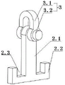
优选地,吊具为板状结构,包括中间的吊柄和两侧的直角钩,吊柄的上部具有与卸扣连接的圆孔,吊柄的下部与直角钩围成两个用于承托槽钢梁的托槽。Preferably, the hanger is a plate-like structure, including a middle hanger and right-angle hooks on both sides, the upper part of the hanger has a round hole connected with the shackle, and the lower part of the hanger and the right-angle hooks form two for supporting Brackets for channel beams.
优选地,卸扣为D型卸扣,包括扣环和连接螺栓,钢丝绳的下端穿设在扣环内,连接螺栓穿过圆孔将扣环锁紧在吊具上。Preferably, the shackle is a D-shaped shackle, including a retaining ring and a connecting bolt, the lower end of the wire rope is inserted in the retaining ring, and the connecting bolt passes through the circular hole to lock the retaining ring on the sling.
优选地,托槽的深度小于槽钢梁的高度,吊柄的长度大于托槽的深度和槽钢梁的高度之和,托槽的槽长与槽钢梁的宽度相匹配。Preferably, the depth of the bracket is less than the height of the channel beam, the length of the hanger is greater than the sum of the depth of the bracket and the height of the channel beam, and the length of the bracket matches the width of the channel beam.
优选地,两组吊具相对于双层贝雷梁的中心点对称布置,同一组的两个吊具前后相对布置。Preferably, the two sets of spreaders are arranged symmetrically with respect to the center point of the double-layer Bailey beam, and the two spreaders of the same group are arranged opposite to each other.
优选地,槽钢梁的下端对应吊具的位置设置有两个挡块,直角钩的水平段贴合嵌设在两个挡块之间。Preferably, the lower end of the channel steel beam is provided with two blocks corresponding to the position of the hanger, and the horizontal section of the right-angle hook is fitted and embedded between the two blocks.
与现有技术相比,本实用新型提供了一种双层贝雷梁吊装结构,具备以下有益效果:Compared with the prior art, the utility model provides a double-layer Bailey beam hoisting structure, which has the following beneficial effects:
1. 本实用新型在双层贝雷梁左右两侧上弦杆上设置有两组吊具,上弦杆的槽钢梁卡在吊具的托槽中,将双层贝雷梁稳稳托起,拆装时,只需将吊具下降或上升一段位置,再转动90度辅助提升,即可完成拆卸和安装。1. The utility model is provided with two sets of spreaders on the upper chords on the left and right sides of the double-layer Bailey beam, and the channel steel beams of the upper chord are stuck in the brackets of the spreader, and the double-layer Bailey beam is stably held up, disassembled and assembled. When the sling is lifted, it is only necessary to lower or raise the spreader for a certain position, and then turn it 90 degrees to assist the lifting, and then the disassembly and installation can be completed.
2. 本实用新型的吊具结构简单、制造成本低、拆装便捷、稳定性高,避免了在吊装时出现脱钩的隐患。2. The hoisting device of the utility model has the advantages of simple structure, low manufacturing cost, convenient disassembly and assembly, high stability, and avoids the hidden danger of decoupling during hoisting.
该装置中未涉及部分均与现有技术相同或可采用现有技术加以实现。The parts not involved in the device are the same as the prior art or can be implemented by using the prior art.
附图说明Description of drawings
为了更清楚地说明本实用新型实施例或现有技术中的技术方案,下面将对实施例中所需要使用的附图作简单的介绍,显而易见地,下面描述中的附图仅仅是本实用新型的一些实施例,对于本领域普通技术人员来讲,在不付出创造性劳动的前提下,还可以根据这些附图获得其他的附图。In order to more clearly illustrate the embodiments of the present invention or the technical solutions in the prior art, the accompanying drawings required in the embodiments will be briefly introduced below. Obviously, the drawings in the following description are only of the present invention. For some embodiments of the present invention, for those of ordinary skill in the art, other drawings can also be obtained from these drawings without any creative effort.
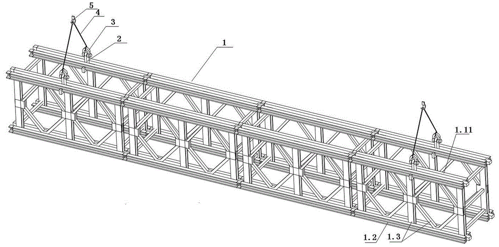
图1为本实施例的整体结构示意图;1 is a schematic diagram of the overall structure of this embodiment;
图2为本实施例的吊具和卸扣的结构示意图;Fig. 2 is the structural representation of the spreader and the shackle of the present embodiment;
图3为本实施例的吊具的结构示意图;3 is a schematic structural diagram of the spreader of the present embodiment;
图4为本实施例的纵向剖视图;Fig. 4 is the longitudinal sectional view of this embodiment;
图5为本实施例中加装挡块后的部分结构示意图。FIG. 5 is a schematic diagram of a part of the structure of this embodiment after adding a stopper.
图中:1-双层贝雷梁;1.11-槽钢梁;1.2-下弦杆;1.3-腹杆;2-吊具;2.1-吊柄;2.11-圆孔;2.2-直角钩;2.3-托槽;3-卸扣;3.1-扣环;3.2-连接螺栓;4-钢丝绳;5-吊钩;6-挡块。In the picture: 1-Double Belay beam; 1.11-Channel steel beam; 1.2-Lower chord; 1.3-Web rod; 2-Sling; 2.1-Hanging handle; 2.11-Round hole; 2.2-Right-angle hook; Slot; 3-shackle; 3.1-buckle; 3.2-connecting bolt; 4-wire rope; 5-hook; 6-stop.
具体实施方式Detailed ways
下面将结合本实用新型实施例中的附图,对本实用新型实施例中的技术方案进行清楚、完整地描述,显然,所描述的实施例仅仅是本实用新型一部分实施例,而不是全部的实施例。The technical solutions in the embodiments of the present utility model will be clearly and completely described below with reference to the accompanying drawings in the embodiments of the present utility model. Obviously, the described embodiments are only a part of the embodiments of the present utility model, rather than all the implementations. example.
在本实用新型的描述中,需要理解的是,术语“上”、“下”、“前”、“后”、“左”、“右”、“顶”、“底”、“内”、“外”等指示的方位或位置关系为基于附图所示的方位或位置关系,仅是为了便于描述本实用新型和简化描述,而不是指示或暗示所指的装置或元件必须具有特定的方位、以特定的方位构造和操作,因此不能理解为对本实用新型的限制。In the description of the present invention, it should be understood that the terms "upper", "lower", "front", "rear", "left", "right", "top", "bottom", "inside", The orientation or positional relationship indicated by "outside" is based on the orientation or positional relationship shown in the accompanying drawings, which is only for the convenience of describing the present invention and simplifying the description, rather than indicating or implying that the indicated device or element must have a specific orientation , are constructed and operated in a specific orientation, and therefore should not be construed as a limitation of the present invention.
本实用新型提供了一种实施例:The utility model provides an embodiment:
如图1所示,一种双层贝雷梁吊装结构,包括双层贝雷梁1,双层贝雷梁1由两道并排设置的贝雷架单元拼接而成,贝雷架单元包括多个依次连接的贝雷架,贝雷架包括上弦杆、下弦杆1.2和连接在两者之间的腹杆1.3,上弦杆包括两道相连接的槽钢梁1.11,本实施例中,双层贝雷梁的结构和连接方式为现有技术,在此不做进一步赘述。As shown in FIG. 1, a double-layer Bailey beam hoisting structure includes a double-layer Bailey beam 1. The double-layer Bailey beam 1 is formed by splicing two Bailey frame units arranged side by side. The Bailey frame unit includes multiple The berets are connected in sequence. The beret includes an upper chord, a lower chord 1.2, and a web 1.3 connected between them. The upper chord includes two connected channel steel beams 1.11. In this embodiment, the double-layered The structure and connection method of the Bailey beam are in the prior art, and will not be further described here.
双层贝雷梁1上靠近左右两侧的位置各设置有一组吊具2,两组吊具2相对于双层贝雷梁1的中心点对称布置,每组吊具2为两个,前后相对设置在两个上弦杆上,吊具2的截面为山字形,上弦杆的两道槽钢梁1.11的底部分别卡接在吊具2的两个托槽2.3中,吊具2的上端伸出上弦杆,且连接有卸扣3,卸扣3上连接有钢丝绳4,同一组吊具2对应的两个钢丝绳4连接在同一起吊装置的吊钩5上。Two sets of
如图2、图3、图4所示,本实施例中,吊具2为板状结构,由4cm厚的钢板一体切割而成,包括中间的吊柄2.1和两侧的直角钩2.2,吊柄2.1的上端具有与卸扣3连接的圆孔2.11,托槽2.3由吊柄2.1的下部与直角钩2.2围成,托槽2.3的深度小于槽钢梁1.11的高度,吊柄2.1的长度大于托槽2.3的深度和槽钢梁1.11的高度之和,保证吊柄2.1可以取出和放入上弦杆的两个槽钢梁1.11之间,并通过托槽2.3将槽钢梁1.11托举;托槽2.3的槽长与槽钢梁1.11的宽度相匹配,可以在吊装双层贝雷梁1过程中保证槽钢梁1.11与吊具2卡紧,防止掉落,水平吊装时,在摩擦力的作用下,吊具2一般不会发生滑动。As shown in Figure 2, Figure 3, Figure 4, in this embodiment, the
在吊装过程中,若出现倾角过大的情况,吊具2会出现一定距离的滑动(在腹杆1.3的竖杆和斜杆之间),可能会存在一定的安全隐患,因此,如图5所示,在槽钢梁1.11的下端对应吊具2的位置设置两个挡块6,直角钩2.2的水平段贴合嵌设在两个挡块6之间,可以对吊具2的位置进行限定,防止倾角过大时发生滑动,而且在吊具2托举槽钢梁1.1之前,可以将吊具2的直角钩2.2嵌入挡块6之间,避免了起吊瞬间吊具2发生倾斜,长期倾斜会对直角钩2.2的刚性造成一定的破坏。During the hoisting process, if the inclination angle is too large, the
本实施例中,吊具2与钢丝绳4之间通过卸扣3连接,承载能力较高,起吊过程不产生转动,能够很好保证连接的紧固,卸扣3为D型卸扣,包括扣环3.1和连接螺栓3.2,钢丝绳4的下端穿设在扣环3.1内,连接螺栓3.2穿过圆孔2.11将扣环3.1锁紧在吊具2上。In this embodiment, the
具体操作步骤:Specific steps:
1. 将同一组吊具2对应的两条钢丝绳4的上端连接在同一起吊装置的吊钩5上(起吊装置为汽车吊),将钢丝绳4的下端连接在卸扣3的扣环3.1内,将扣环3.1通过连接螺栓3.2连接在吊柄2.1的圆孔2.11中;1. Connect the upper ends of the two
2. 通过人工牵引将吊具2放入上弦杆的两横梁1.11之间的间隙中,待吊具2的直角钩2.2位于槽钢梁1.11下方时,将吊具2水平转动90度,再通过缓慢起吊吊具2,两个的托槽2.3将两槽钢梁1.11牢固拖住;2. Put the
3. 将双层贝雷梁1通过起吊装置吊运至安装场地,带动吊具2下降,待双层贝雷梁1落在安装位置后,缓慢将吊具2下降一定高度,再人工将吊具2水平转动90度,即可辅助将吊具2调离双层贝雷梁1,完成脱钩。3. Lift the double-layer Bailey beam 1 to the installation site through the hoisting device, and drive the
以上所述,仅为本实用新型较佳的具体实施方式,但本实用新型的保护范围并不局限于此,任何熟悉本技术领域的技术人员在本实用新型揭露的技术范围内,根据本实用新型的技术方案及其实用新型构思加以等同替换或改变,都应涵盖在本实用新型的保护范围之内。The above descriptions are only the preferred specific embodiments of the present invention, but the protection scope of the present invention is not limited to this. Equivalent replacement or modification of the new technical solution and its utility model concept shall be included within the protection scope of the present utility model.
Claims (6)
Priority Applications (1)
| Application Number | Priority Date | Filing Date | Title |
|---|---|---|---|
| CN202122845743.7U CN216586185U (en) | 2021-11-19 | 2021-11-19 | A double-layer Bailey beam hoisting structure |
Applications Claiming Priority (1)
| Application Number | Priority Date | Filing Date | Title |
|---|---|---|---|
| CN202122845743.7U CN216586185U (en) | 2021-11-19 | 2021-11-19 | A double-layer Bailey beam hoisting structure |
Publications (1)
| Publication Number | Publication Date |
|---|---|
| CN216586185U true CN216586185U (en) | 2022-05-24 |
Family
ID=81647833
Family Applications (1)
| Application Number | Title | Priority Date | Filing Date |
|---|---|---|---|
| CN202122845743.7U Active CN216586185U (en) | 2021-11-19 | 2021-11-19 | A double-layer Bailey beam hoisting structure |
Country Status (1)
| Country | Link |
|---|---|
| CN (1) | CN216586185U (en) |
-
2021
- 2021-11-19 CN CN202122845743.7U patent/CN216586185U/en active Active
Similar Documents
| Publication | Publication Date | Title |
|---|---|---|
| CN109853404A (en) | Steel truss girder bridge cantilever assembly erection method | |
| CN106192776A (en) | A kind of big Span Continuous Flexible arch bridge with steel truss beam free cantilever erection construction technology | |
| CN115724331A (en) | Prefabricated box girder hoisting device and rapid construction method | |
| CN205188797U (en) | Concrete tied arch bridge jib casts anchor and holds connection structure | |
| CN117602489A (en) | A method for lifting and transporting large-diameter concrete pipe pile sections | |
| CN107419665B (en) | A large-span steel beam hoisting spreader and a method for hoisting steel beams | |
| CN105780659A (en) | Lifting appliance special for erection of large-tonnage steel box beam segment in non-stayed cable area of cable-stayed bridge | |
| CN111576227B (en) | Construction method of main and secondary arches of double-wing arch bridge and the hoisting equipment used therein | |
| CN209177842U (en) | Fixed system | |
| CN119777280A (en) | A walking bridge construction hanging basket device and operation method thereof | |
| CN219260998U (en) | An anchor cable tensioner | |
| CN214301281U (en) | Construction platform for connecting steel truss girder and bridge deck slab | |
| CN218668435U (en) | Span structure string supporting platform | |
| CN111453600A (en) | A kind of prefabricated bridge pier column lifting device and lifting method | |
| CN217627283U (en) | Asynchronous hanging basket with triangular truss type hoisting equipment | |
| CN111453630B (en) | Bridge deck crane and use method thereof | |
| CN215364466U (en) | Hoisting device for precast concrete beam in construction site | |
| CN212954042U (en) | Lattice formula cable saddle hoist and mount portal | |
| CN116281560A (en) | Hanging beam steel frame for T beam hoisting, hanging beam system and T beam prefabrication and hoisting method | |
| CN212559207U (en) | Bridge floor crane | |
| CN211228136U (en) | A combined construction platform for prefabricated T beams with negative bending moment tension | |
| CN210340110U (en) | Two T board hoisting structure of large-span assembled | |
| CN209210183U (en) | fixed system | |
| CN203188109U (en) | Multi-span ground anchor type suspension bridge | |
| CN208022590U (en) | One kind overhauling hoisting frame based on steel construction boiler plant |
Legal Events
| Date | Code | Title | Description |
|---|---|---|---|
| GR01 | Patent grant | ||
| GR01 | Patent grant | ||
| PP01 | Preservation of patent right |
Effective date of registration: 20250908 Granted publication date: 20220524 |
|
| PP01 | Preservation of patent right |