CN216575104U - Numerical control punching machine with good heat dissipation effect for precision mechanical engineering - Google Patents
Numerical control punching machine with good heat dissipation effect for precision mechanical engineering Download PDFInfo
- Publication number
- CN216575104U CN216575104U CN202122194781.0U CN202122194781U CN216575104U CN 216575104 U CN216575104 U CN 216575104U CN 202122194781 U CN202122194781 U CN 202122194781U CN 216575104 U CN216575104 U CN 216575104U
- Authority
- CN
- China
- Prior art keywords
- fixedly connected
- box body
- box
- punching machine
- heat dissipation
- Prior art date
- Legal status (The legal status is an assumption and is not a legal conclusion. Google has not performed a legal analysis and makes no representation as to the accuracy of the status listed.)
- Active
Links
- 238000004080 punching Methods 0.000 title claims abstract description 75
- 230000017525 heat dissipation Effects 0.000 title claims abstract description 19
- 230000000694 effects Effects 0.000 title claims abstract description 18
- 238000011089 mechanical engineering Methods 0.000 title claims abstract description 13
- 239000000463 material Substances 0.000 claims abstract description 48
- 238000012545 processing Methods 0.000 claims abstract description 25
- 238000007599 discharging Methods 0.000 claims abstract description 14
- 239000002699 waste material Substances 0.000 claims description 19
- 238000005192 partition Methods 0.000 claims description 4
- 238000007664 blowing Methods 0.000 claims 1
- 238000000034 method Methods 0.000 abstract description 5
- 230000008569 process Effects 0.000 abstract description 5
- 238000003754 machining Methods 0.000 description 12
- 239000000047 product Substances 0.000 description 9
- 230000000903 blocking effect Effects 0.000 description 3
- 239000013589 supplement Substances 0.000 description 3
- 230000009471 action Effects 0.000 description 1
- 230000004075 alteration Effects 0.000 description 1
- 230000009286 beneficial effect Effects 0.000 description 1
- 238000011161 development Methods 0.000 description 1
- 238000004049 embossing Methods 0.000 description 1
- 238000002474 experimental method Methods 0.000 description 1
- 230000003116 impacting effect Effects 0.000 description 1
- 239000002184 metal Substances 0.000 description 1
- 238000012986 modification Methods 0.000 description 1
- 230000004048 modification Effects 0.000 description 1
- 238000003825 pressing Methods 0.000 description 1
- 239000007921 spray Substances 0.000 description 1
- 238000006467 substitution reaction Methods 0.000 description 1
Images

Landscapes
- Perforating, Stamping-Out Or Severing By Means Other Than Cutting (AREA)
Abstract
The utility model discloses a numerical control punching machine with a good heat dissipation effect for precision mechanical engineering, which comprises a box body and a material discharging box, wherein a through groove is formed in the middle end of the top of the box body, a processing seat is fixedly connected to the corresponding position, located at the top of the box body, of the through groove, limiting plates are fixedly connected to the front side and the rear side of the upper end of the inner side of the processing seat, a fixing rod is fixedly connected to the left end of the inner side of each limiting plate, and a baffle is movably connected to the middle end of the outer surface of each fixing rod. The punching machine solves the problems that in the actual application process of the existing punching machine, the punching tool bit of the existing punching machine can generate high temperature when punching a workpiece, the punching machine does not have the heat dissipation capability, the service life of the punching tool bit is further shortened, meanwhile, the punching machine is operated manually, the working efficiency is low, and the existing punching machine has certain risk.
Description
Technical Field
The utility model relates to the technical field of numerical control punching machines, in particular to a numerical control punching machine with good heat dissipation effect for precision mechanical engineering.
Background
The punching machine is a movable part for forcing metal to enter a die in sheet processing, stamping, mould pressing, embossing and the like, and along with the continuous development of the machining industry, when parts are processed in the machining industry, the punching machine is required to punch so as to be convenient for connection or fixation. However, in the actual application process of the existing punching machine, when the punching tool bit of the existing punching machine punches a workpiece, high temperature can be generated, the punching machine does not have heat dissipation capacity, the service life of the punching tool bit is further shortened, meanwhile, the punching machine is mostly operated manually, the working efficiency is low, and meanwhile, the existing punching machine has certain risk, and therefore the numerical control punching machine with the good heat dissipation effect for the precision mechanical engineering is provided.
SUMMERY OF THE UTILITY MODEL
The utility model aims to provide a numerical control punching machine with good heat dissipation effect for precision mechanical engineering, which has the advantages of good heat dissipation effect, high working efficiency and high safety, and solves the problems that in the practical application process of the existing punching machine, a punching tool bit of the existing punching machine can generate high temperature when punching a workpiece, the punching machine does not have heat dissipation capability, and further the service life of the punching tool bit is shortened, and meanwhile, the punching machine is mostly operated manually, so that the working efficiency is low, and meanwhile, the existing punching machine has certain risk.
In order to achieve the purpose, the utility model provides the following technical scheme: a numerical control punching machine with good heat dissipation effect for precision mechanical engineering comprises a box body and a material placing box, wherein a through groove is formed in the middle end of the top of the box body, the through groove is fixedly connected with a processing seat at the corresponding position of the top of the box body, limiting plates are fixedly connected to the front side and the rear side of the upper end of the inner side of the processing seat, a fixing rod is fixedly connected to the left end of the inner side of the limiting plate, a baffle is movably connected to the middle end of the outer surface of the fixing rod, torsion springs are sleeved at the front end and the rear end of the outer surface of the fixing rod, an impact hole is formed in the middle end of the bottom of the inner side of the processing seat, a vent plate is fixedly connected to the top of the limiting plate, a nozzle is fixedly installed on one side of the vent plate, a fixing frame is fixedly connected to the lower end of the right side of the material placing box, an air cylinder is fixedly installed at the middle end of the right side of the fixing frame, a push plate is fixedly connected to the extending end of the top of the inner cavity of the box body, and a material guide baffle is fixedly connected between the lower end of the right side of the inner cavity of the box, the middle end of the bottom of the inner cavity of the box body is fixedly provided with a refrigerator, and the air outlet end of the refrigerator is communicated with one side of the vent plate through a pipeline.
Preferably, a control panel is fixedly mounted at the left end of the top of the box body, a guide chute is formed in the left end of the top of the box body, the guide chute is located at the corresponding position of the top of the inner cavity of the box body and fixedly connected with a fixed cover, a material receiving box is arranged on the inner side of the fixed cover, and a handle is fixedly connected to the front surface of the material receiving box.
Preferably, the rear end of the top of the box body is fixedly connected with a support, the middle end of the top of the support is fixedly provided with a hydraulic telescopic rod, and the extending end of the hydraulic telescopic rod is fixedly connected with a punching head.
Preferably, the left side of the processing seat is fixedly connected with a material discharging box, and a workpiece to be processed is placed on the inner side of the material discharging box.
Preferably, the middle end on the right side of the box body is provided with a waste guide groove, and the lower end on the right side of the box body is provided with a waste collecting box.
Preferably, the lower end of the left side of the processing seat is fixedly connected with a material guide platform, and one side of the material guide platform is provided with an inclined plane.
Compared with the prior art, the utility model has the following beneficial effects:
the utility model starts the work of the punching machine according to the set program by the control panel after placing the workpiece to be processed in the discharging box through the function of the discharging box, then the refrigerating machine can convey the refrigerated air into the ventilating plate after the work, the refrigerated air is sprayed out from the nozzle to form a cold air waterfall, then the air cylinder drives the push plate to extend out and pushes the workpiece to be processed at the bottommost part of the inner side of the discharging box to enter the processing seat, the position of the entering workpiece to be processed is limited under the coordination of the limiting plate and the baffle plate, then the air cylinder drives the push plate to reset, then the hydraulic telescopic rod drives the punching head to extend out, the punching work of the workpiece to be processed can be realized under the coordination of the impact hole, the waste materials generated by punching can enter the waste material collecting box through the chute, the material guiding baffle plate and the waste material guiding groove to be collected, and simultaneously, the waterfall can blow the punching head during punching to synchronously radiate heat, the normal use of the punching head is ensured, the purpose of good heat dissipation effect is realized, then, the hydraulic telescopic rod drives the punching head to reset, the air cylinder can drive the push plate to extend out again, further, the workpiece to be machined at the bottommost part of the inner side of the material placing box is pushed to enter the machining seat again, after the workpiece to be machined enters the machining seat, the machined part after machining is pushed to move to the left in the machining seat, in addition, under the coordination of a torsional spring, the blocking of the finished product part is released, the formed product part falls into the material receiving box through the guiding of the material guiding platform and the material guiding groove, further, the collection of the finished product part is convenient, after the circulation, a worker only needs to supplement the workpiece to be machined in the material placing box, the purposes of working efficiency and high safety are achieved, the problems that the punching tool bit of the existing punching machine can generate high temperature when punching the machined part in the actual application process, and the punching machine does not have the heat dissipation capability are solved, and then reduced the life of the tool bit that punches a hole, simultaneously, the piercing press is many through manual operation, and work efficiency is low, possesses the problem of certain risk simultaneously.
Drawings
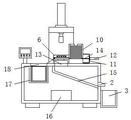
FIG. 1 is a schematic structural view of the present invention;
FIG. 2 is a schematic cross-sectional view of the present invention;
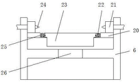
FIG. 3 is a schematic cross-sectional view of the machining base of the present invention viewed from the left.
In the figure: 1. a box body; 2. a waste chute; 3. a waste collection box; 4. a material receiving box; 5. a control panel; 6. processing a base; 7. a punching head; 8. a hydraulic telescopic rod; 9. a support; 10. placing a material box; 11. a fixed mount; 12. a cylinder; 13. a through groove; 14. pushing the plate; 15. a material guiding clapboard; 16. a refrigerator; 17. a fixed cover; 18. a material guide chute; 19. a material guide table; 20. a limiting plate; 21. a breather plate; 22. a torsion spring; 23. a baffle plate; 24. a nozzle; 25. fixing the rod; 26. and (6) impacting the hole.
Detailed Description
The technical solutions in the embodiments of the present invention will be clearly and completely described below with reference to the drawings in the embodiments of the present invention, and it is obvious that the described embodiments are only a part of the embodiments of the present invention, and not all of the embodiments. All other embodiments, which can be derived by a person skilled in the art from the embodiments given herein without making any creative effort, shall fall within the protection scope of the present invention.
In the description of the application, it is to be noted that, unless otherwise explicitly specified or limited, the terms "mounted," "disposed," "connected," and the like are to be construed broadly, such as "connected," which may be fixedly connected, detachably connected, or integrally connected; can be mechanically or electrically connected; they may be connected directly or indirectly through intervening media, or they may be interconnected between two elements. The specific meaning of the above terms in the present application can be understood in a specific case by those of ordinary skill in the art.
The box body 1, the waste guide groove 2, the waste collecting box 3, the material receiving box 4, the control panel 5, the processing seat 6, the punching head 7, the hydraulic telescopic rod 8, the support 9, the discharging box 10, the fixing frame 11, the cylinder 12, the through groove 13, the push plate 14, the material guide partition plate 15, the refrigerator 16, the fixing cover 17, the material guide groove 18, the material guide platform 19, the limiting plate 20, the air vent plate 21, the torsion spring 22, the baffle plate 23, the nozzle 24, the fixing rod 25 and the impact hole 26 are all universal standard parts or parts known by a person skilled in the art, and the structure and the principle of the utility model can be known by technical manuals or conventional experimental methods.
Referring to fig. 1-3, a numerical control punching machine with good heat dissipation effect for precision mechanical engineering comprises a box body 1 and a material placing box 10, a control panel 5 is fixedly installed at the left end of the top of the box body 1, a material guide chute 18 is arranged at the left end of the top of the box body 1, a fixed cover 17 is fixedly connected at the corresponding position of the material guide chute 18 at the top of the inner cavity of the box body 1, a material receiving box 4 is arranged at the inner side of the fixed cover 17, a handle is fixedly connected with the front surface of the material receiving box 4, a support 9 is fixedly connected at the rear end of the top of the box body 1, a hydraulic telescopic rod 8 is fixedly installed at the middle end of the top of the support 9, a punching head 7 is fixedly connected at the extending end of the hydraulic telescopic rod 8, a through groove 13 is arranged at the middle end of the top of the box body 1, a processing seat 6 is fixedly connected at the corresponding position of the top of the through groove 13, a material guide platform 19 is fixedly connected at the lower end of the left side of the processing seat 6, and an inclined plane is arranged at one side of the material guide platform 19, the front side and the rear side of the upper end of the inner side of the processing seat 6 are fixedly connected with a limiting plate 20, the left end of the inner side of the limiting plate 20 is fixedly connected with a fixing rod 25, the middle end of the outer surface of the fixing rod 25 is movably connected with a baffle plate 23, the front end and the rear end of the outer surface of the fixing rod 25 are sleeved with a torsion spring 22, the middle end of the bottom of the inner side of the processing seat 6 is provided with an impact hole 26, the top of the limiting plate 20 is fixedly connected with a vent plate 21, one side of the vent plate 21 is fixedly provided with a nozzle 24, the left side of the processing seat 6 is fixedly connected with a discharging box 10, a workpiece to be processed is placed in the discharging box 10, the lower end of the right side of the discharging box 10 is fixedly connected with a fixing frame 11, the middle end of the right side of the fixing frame 11 is fixedly provided with an air cylinder 12, the extending end of the air cylinder 12 is fixedly connected with a push plate 14, a guide baffle plate 15 is fixedly connected between the left end of the top of the inner cavity of the box 1 and the lower end of the right side of the inner cavity of the box 1 is provided with a waste guide groove 2, the lower end of the right side of the box body 1 is provided with a waste collecting box 3, the middle end of the bottom of the inner cavity of the box body 1 is fixedly provided with a refrigerator 16, the air outlet end of the refrigerator 16 is communicated with one side of an air vent plate 21 through a pipeline, after a workpiece to be machined is placed in the refrigerator through the action of a material placing box 10, the control panel 5 starts the punching machine to work according to a set program, then, the refrigerator 16 can convey the refrigerated air into the air vent plate 21 after working, the refrigerated air is sprayed out from a nozzle 24 to form a cold air waterfall, then, an air cylinder 12 drives a push plate 14 to extend out and pushes the workpiece to be machined at the bottommost part in the material placing box 10 to enter a machining seat 6, under the matching of a limiting plate 20 and a baffle plate 23, the position of the entering workpiece to be machined is limited, then, the air cylinder 12 drives the push plate 14 to reset, then, a hydraulic pressure 8 drives a punching head 7 to extend out and under the matching of an impact hole 26, the punching work of the workpiece to be processed can be realized, the waste generated by punching can enter the waste collecting box 3 for collection through the chute 13, the guide partition plate 15 and the waste guide groove 2, meanwhile, the cold air waterfall can blow the capability of synchronously radiating the punching head 7 during punching, the normal use of the punching head 7 is ensured, the purpose of good radiating effect is realized, then, the hydraulic telescopic rod 8 drives the punching head 7 to reset, the air cylinder 12 can drive the push plate 14 to extend out again, the workpiece to be processed at the bottommost part inside the material placing box 10 is further pushed to enter the processing seat 6, after the workpiece to be processed enters the processing seat 6, the processed workpiece can be pushed to move to the left in the processing seat 6, in addition, under the matching of the torsion spring 22, the blocking of the finished product is released, the finished product falls into the material collecting box 4 through the guide of the guide platform 19 and the guide chute 18, and the collection of the finished product is further facilitated, after the circulation, the worker only needs to supplement the workpiece to be processed in the discharging box 10, and the purposes of working efficiency and high safety are achieved.
When in use, after a workpiece to be processed is placed in the discharging box 10, the control panel 5 starts the punching machine to work according to a set program, then the refrigerating machine 16 can convey refrigerated air into the ventilating plate 21 after working and spray the air out of the nozzle 24 to form a cold air waterfall, then the air cylinder 12 drives the push plate 14 to extend out and push the workpiece to be processed at the bottommost part of the inner side of the discharging box 10 into the processing seat 6, the position of the workpiece to be processed is limited under the matching of the limiting plate 20 and the baffle plate 23, then the air cylinder 12 drives the push plate 14 to reset, then the hydraulic telescopic rod 8 drives the punching head 7 to extend out, and the punching work of the workpiece to be processed can be realized under the matching of the impact hole 26, and waste materials generated by punching can enter the waste material collecting box 3 through the chute 13, the guide partition plate 15 and the waste material guide groove 2 to be collected, meanwhile, the cold air waterfall can blow the capability of synchronously radiating the punching head 7 during punching, the normal use of the punching head 7 is ensured, and the purpose of good radiating effect is realized, then, the hydraulic telescopic rod 8 drives the punching head 7 to reset, the air cylinder 12 drives the push plate 14 to extend out again, further, the workpiece to be machined at the bottommost part of the inner side of the material discharge box 10 is pushed to enter the machining seat 6 again, after the workpiece to be machined enters the machining seat 6, the machined workpiece after machining can be pushed to move leftwards in the machining seat 6, and under the coordination of the torsion spring 22, the blocking of the finished product is released, the finished product falls into the material receiving box 4 through the guide of the material guide platform 19 and the material guide groove 18, the collection of the finished product is further facilitated, after the circulation, a worker only needs to supplement the workpiece to be machined in the material discharge box 10, the purposes of working efficiency and high safety are achieved, and the problem that the existing punching machine is in the practical application process is solved, its tool bit that punches a hole can produce high temperature when punching press the machined part, and the piercing press does not possess the heat-sinking capability, and then has reduced the life of tool bit that punches a hole, and simultaneously, the piercing press is many through manual operation, and work efficiency is low, possesses the problem of certain risk simultaneously.
Although embodiments of the present invention have been shown and described, it will be appreciated by those skilled in the art that changes, modifications, substitutions and alterations can be made in these embodiments without departing from the principles and spirit of the utility model, the scope of which is defined in the appended claims and their equivalents.
Claims (6)
1. The utility model provides a numerical control piercing press that radiating effect is good for precision machinery engineering, includes box (1) and blowing box (10), its characterized in that: the middle end of the top of the box body (1) is provided with a through groove (13), the through groove (13) is located at the corresponding position of the top of the box body (1) and is fixedly connected with a processing seat (6), limiting plates (20) are fixedly connected with the front and back sides of the inner upper end of the processing seat (6), a fixing rod (25) is fixedly connected with the left end of the inner side of the limiting plate (20), a baffle (23) is movably connected with the middle end of the outer surface of the fixing rod (25), torsion springs (22) are sleeved at the front and back ends of the outer surface of the fixing rod (25), an impact hole (26) is formed at the middle end of the inner bottom of the processing seat (6), a vent plate (21) is fixedly connected with the top of the limiting plate (20), a nozzle (24) is fixedly installed at one side of the vent plate (21), a fixing frame (11) is fixedly connected with the lower end of the right side of the discharging box (10), and an air cylinder (12) is fixedly installed at the middle end of the right side of the fixing frame (11), the air outlet device is characterized in that a push plate (14) is fixedly connected to the extending end of the air cylinder (12), a material guide partition plate (15) is fixedly connected between the left end of the top of the inner cavity of the box body (1) and the lower end of the right side of the inner cavity of the box body (1), a refrigerator (16) is fixedly mounted at the middle end of the bottom of the inner cavity of the box body (1), and the air outlet end of the refrigerator (16) is communicated with one side of the air vent plate (21) through a pipeline.
2. The numerical control punching machine with good heat dissipation effect for precision mechanical engineering according to claim 1, characterized in that: the left end fixed mounting at the top of the box body (1) is provided with a control panel (5), the left end at the top of the box body (1) is provided with a guide chute (18), the guide chute (18) is located at the corresponding position of the top of the inner cavity of the box body (1) and is fixedly connected with a fixed cover (17), the inner side of the fixed cover (17) is provided with a material receiving box (4), and the front surface of the material receiving box (4) is fixedly connected with a handle.
3. The numerical control punching machine with good heat dissipation effect for precision mechanical engineering according to claim 1, characterized in that: the box is characterized in that a support (9) is fixedly connected to the rear end of the top of the box body (1), a hydraulic telescopic rod (8) is fixedly mounted at the middle end of the top of the support (9), and a punching head (7) is fixedly connected to the extending end of the hydraulic telescopic rod (8).
4. The numerical control punching machine with good heat dissipation effect for precision mechanical engineering according to claim 1, characterized in that: the left side of the processing seat (6) is fixedly connected with a material placing box (10), and a workpiece to be processed is placed on the inner side of the material placing box (10).
5. The numerical control punching machine with good heat dissipation effect for precision mechanical engineering according to claim 1, characterized in that: the middle end on the right side of the box body (1) is provided with a waste guide groove (2), and the lower end on the right side of the box body (1) is provided with a waste collecting box (3).
6. The numerical control punching machine with good heat dissipation effect for precision mechanical engineering according to claim 1, characterized in that: the lower end of the left side of the processing seat (6) is fixedly connected with a material guide platform (19), and one side of the material guide platform (19) is provided with an inclined plane.
Priority Applications (1)
| Application Number | Priority Date | Filing Date | Title |
|---|---|---|---|
| CN202122194781.0U CN216575104U (en) | 2021-09-11 | 2021-09-11 | Numerical control punching machine with good heat dissipation effect for precision mechanical engineering |
Applications Claiming Priority (1)
| Application Number | Priority Date | Filing Date | Title |
|---|---|---|---|
| CN202122194781.0U CN216575104U (en) | 2021-09-11 | 2021-09-11 | Numerical control punching machine with good heat dissipation effect for precision mechanical engineering |
Publications (1)
| Publication Number | Publication Date |
|---|---|
| CN216575104U true CN216575104U (en) | 2022-05-24 |
Family
ID=81636231
Family Applications (1)
| Application Number | Title | Priority Date | Filing Date |
|---|---|---|---|
| CN202122194781.0U Active CN216575104U (en) | 2021-09-11 | 2021-09-11 | Numerical control punching machine with good heat dissipation effect for precision mechanical engineering |
Country Status (1)
| Country | Link |
|---|---|
| CN (1) | CN216575104U (en) |
Cited By (1)
| Publication number | Priority date | Publication date | Assignee | Title |
|---|---|---|---|---|
| CN116871428A (en) * | 2023-09-07 | 2023-10-13 | 江苏恒力达机械有限公司 | Radiating fin blanking machine |
-
2021
- 2021-09-11 CN CN202122194781.0U patent/CN216575104U/en active Active
Cited By (1)
| Publication number | Priority date | Publication date | Assignee | Title |
|---|---|---|---|---|
| CN116871428A (en) * | 2023-09-07 | 2023-10-13 | 江苏恒力达机械有限公司 | Radiating fin blanking machine |
Similar Documents
| Publication | Publication Date | Title |
|---|---|---|
| CN117161187B (en) | Plate stamping forming device for precise metal plate | |
| CN211990574U (en) | Stamping die | |
| CN211438549U (en) | Bumper punching and welding all-in-one machine with replaceable punching die | |
| CN212945108U (en) | Punch press is used in metal bottle lid production | |
| CN220073155U (en) | Bearing ring stamping device for bearing forging | |
| CN214556891U (en) | A waste collection device for punching machines | |
| CN217941511U (en) | Sheet metal stamping device | |
| CN223699065U (en) | A stamping die for cutting lead wire frames | |
| CN213162520U (en) | Stamping device is used in production of plastic-aluminum combined cover for infusion bottle | |
| CN212264248U (en) | Stamping device for machining explosion-proof groove on aluminum shell | |
| CN210253807U (en) | Punching machine is used in aluminum alloy ex-trusions processing | |
| CN213997579U (en) | Auxiliary appliance for punching machine for computer cooling fin | |
| CN210280321U (en) | Stamping device is used in aluminum product processing | |
| CN211276119U (en) | Punching die for metal plate of electronic box | |
| CN214108428U (en) | Automobile parts stamping device | |
| CN217121437U (en) | Stamping device with debris collection function | |
| CN215845097U (en) | Cooling device for hardware production | |
| CN218903243U (en) | Processing punch press capable of automatically collecting waste materials | |
| CN219188505U (en) | Noise reduction type forging press | |
| CN223028731U (en) | Laser etching equipment for mold pattern processing | |
| CN212551355U (en) | Forming die is used in steel construction container production | |
| CN223775761U (en) | A stamping device for hardware mold processing | |
| CN224011061U (en) | Waste recycling mechanism of punch press | |
| CN219817812U (en) | Combined punch press with protective structure | |
| CN221695053U (en) | An automated tooling for assisting blanking die material removal |
Legal Events
| Date | Code | Title | Description |
|---|---|---|---|
| GR01 | Patent grant | ||
| GR01 | Patent grant |