Rehabilitation training device for orthopedic nursing
Technical Field
The utility model relates to the field of rehabilitation training devices, in particular to a rehabilitation training device for orthopedic nursing.
Background
Orthopedics is one of the most common departments of various hospitals, mainly studies the anatomy, physiology and pathology of the skeletal muscle system, and maintains and develops the normal form and function of the system by using medicines, operations and physical methods, and orthopedic patients need to supplement nutrition after operations and also need to exercise appropriately to make bones and muscles better recover the preoperative state to consolidate the operation effect, so that a rehabilitation training device is indispensable;
however, the rehabilitation training device for orthopedic nursing at the present stage has some disadvantages, for example, application No. 202010880148.4 discloses "a lower limb training rehabilitation device for orthopedic nursing", when a user uses the device, the user performs rehabilitation training on lower limbs, the user can make the lying process harder due to the inconvenience of the lower limbs when lying on a bottom plate, the user often needs the assistance of external personnel to lie flat, and when the user lies flat, only two legs can perform rehabilitation, if the user's both arms also need to perform rehabilitation training, the user needs to additionally use the rehabilitation training device to perform rehabilitation training.
SUMMERY OF THE UTILITY MODEL
The utility model mainly aims to provide a rehabilitation training device for orthopedic nursing, which can effectively solve the technical problems in the background technology.
In order to achieve the purpose, the utility model adopts the technical scheme that:
the utility model provides a rehabilitation training device is used in orthopedics nursing, includes bottom plate and running-board, the preceding terminal surface fixed mounting of bottom plate has the protection casing, the both sides surface movable mounting of bottom plate has the arm strength exercise board, the upper surface movable mounting of bottom plate has the running-board, the place ahead movable mounting that the upper surface of bottom plate is located the running-board has the backup plate, a side surface of bottom plate is close to the front end and is equipped with the controller, the inside that the preceding terminal surface both sides of bottom plate just are located the protection casing is equipped with the motor, the upper surface of bottom plate is close to both sides and inlays and be equipped with the guide arm.
Preferably, the upper surface of the arm strength exercising plate is provided with a slide way, a slide rod is arranged inside the slide way, a push-pull handle is sleeved on the surface of the slide rod, an arc-shaped spring is sleeved on one side, located on the push-pull handle, of the surface of the slide rod, and a slide block is fixedly mounted on the rear surface of the arm strength exercising plate.
Preferably, the spout has been seted up on the both sides surface of bottom plate, the upper surface of bottom plate has been close to the rear end both sides and has been seted up the shifting chute, the notch of shifting chute is equipped with flexible protecting band, the upper surface of bottom plate has been close to the front end and has been seted up the inner groovy, the inside lower surface of inner groovy is close to rear end both sides fixed mounting has the backstop piece, the slider inlays to be established in the spout.
Preferably, the upper surface of the backup plate is provided with a protection pad, the lower surface of the backup plate is provided with support rods close to two sides of the front end, the inside of the support rods is close to the upper end and the lower end, through holes are formed in the upper end and the lower end, the inside of the support rods is close to the upper end, a connecting block is movably mounted on the upper end, and the support rods are connected with the backup plate through the connecting block.
Preferably, the output fixed mounting of motor has the threaded rod, the surperficial threaded connection of threaded rod has the collets, the inside of collets is close to the below and sets up threaded hole, the inside of collets is close to the top and is equipped with spacing axle, the lower pot head of bracing piece is established on the surface of spacing axle, the one end of threaded rod extends in the inner groovy and connects in the backstop piece.
Preferably, the lower surface of the pedal is fixedly provided with rebound blocks close to two sides, the surface of the guide rod is sleeved with a return spring, the surface of the guide rod is fixedly sleeved with anti-collision blocks close to two ends, the rebound blocks are sleeved on the surface of the guide rod, and the guide rod is embedded in the moving groove.
Compared with the prior art, the utility model has the following beneficial effects:
according to the arm strength exercising plate, the motor can be used for controlling the supporting rod to stand up, and when the supporting rod stands up, the backup plate is inclined to stand up, so that a user can conveniently lie on the backup plate, after the user leans against the backup plate, the controller is used for controlling the motor to rotate reversely, the backup plate descends again and is embedded in the inner groove, and therefore the rehabilitation exerciser can lie on the bottom plate without assistance of other people, rehabilitation training is more conveniently carried out, the arm strength exercising plate can be used for carrying out rehabilitation training on the arms of the user, and the position of the arm strength exercising plate can be adjusted according to the height of the user.
Drawings
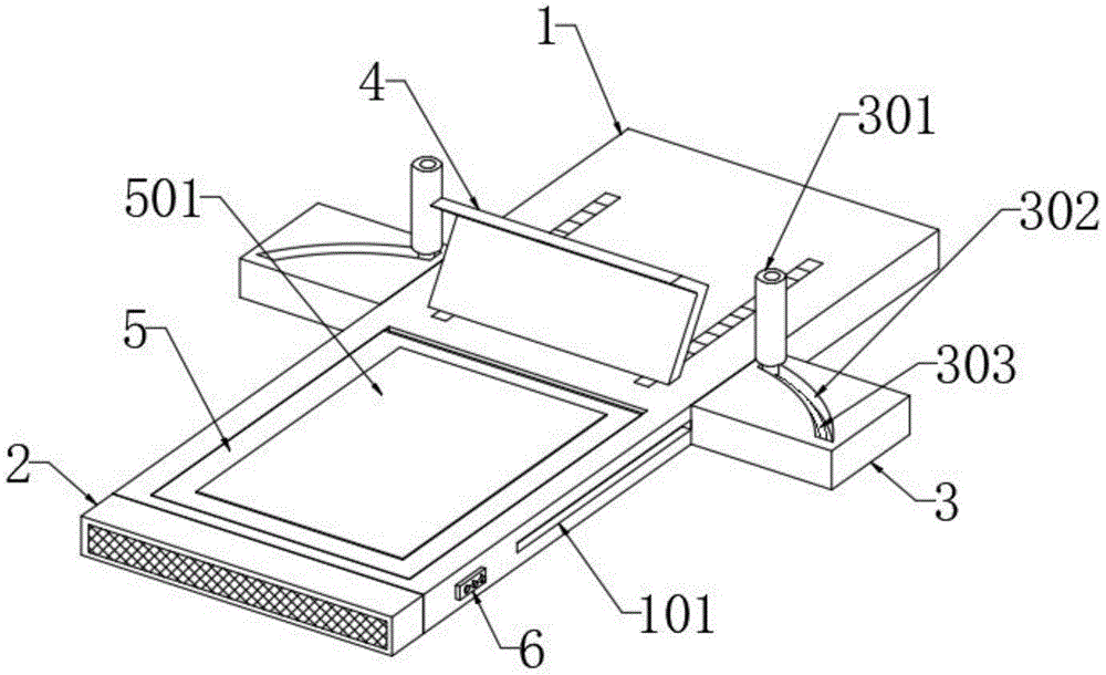
FIG. 1 is an overall structure diagram of a rehabilitation training device for orthopedic nursing according to the present invention;
FIG. 2 is a schematic view of the development of a backup plate of the rehabilitation training device for orthopedic nursing according to the present invention;
FIG. 3 is an enlarged view of the portion A of the rehabilitation training device for orthopedic nursing in FIG. 2;
fig. 4 is a partial sectional view showing the installation of the foot pedal of the rehabilitation training device for orthopedic nursing according to the present invention.
In the figure: 1. a base plate; 101. a chute; 102. a moving groove; 103. an inner groove; 104. a stop block; 2. a protective cover; 3. an arm strength exercising board; 301. a push-pull handle; 302. a slideway; 303. a slide bar; 4. a foot pedal; 401. a rebound block; 5. a backup plate; 501. a pad; 502. a support bar; 503. a through hole; 6. a controller; 7. a motor; 701. a threaded rod; 702. sleeving blocks; 703. a limiting shaft; 8. a guide bar; 801. a return spring; 802. an anti-collision block.
Detailed Description
In order to make the technical means, the creation characteristics, the achievement purposes and the effects of the utility model easy to understand, the utility model is further described with the specific embodiments.
Example 1
As shown in fig. 1-4, a rehabilitation training device for orthopedic nursing comprises a bottom plate 1 and a pedal plate 4, a protective cover 2 is fixedly installed on the front end surface of the bottom plate 1, arm exercising plates 3 are movably installed on the surfaces of the two sides of the bottom plate 1, rehabilitation training can be performed on the arms of a user by using the arm exercising plates 3, the arm exercising plates 3 can be adjusted in position according to the height of the user, the pedal plate 4 is movably installed on the upper surface of the bottom plate 1, a backup plate 5 is movably installed on the upper surface of the bottom plate 1 in front of the pedal plate 4, a controller 6 is arranged on the surface of one side of the bottom plate 1 close to the front end, a motor 7 is arranged on the two sides of the front end surface of the bottom plate 1 and in the protective cover 2, and guide rods 8 are embedded on the upper surface of the bottom plate 1 close to the two sides;
a slide way 302 is arranged on the upper surface of the arm strength exercising plate 3, a slide rod 303 is arranged inside the slide way 302, a push-pull handle 301 is sleeved on the surface of the slide rod 303, an arc-shaped spring is sleeved on one side, located on the push-pull handle 301, of the surface of the slide rod 303, and a slide block is fixedly arranged on the rear surface of the arm strength exercising plate 3; the surface of two sides of the bottom plate 1 is provided with sliding grooves 101, two sides of the upper surface of the bottom plate 1 close to the rear end are provided with moving grooves 102, the notch of the moving groove 102 is provided with a telescopic protective belt, the upper surface of the bottom plate 1 close to the front end is provided with an inner groove 103, two sides of the inner lower surface of the inner groove 103 close to the rear end are fixedly provided with stop blocks 104, and a sliding block is embedded in the sliding groove 101; a protection pad 501 is arranged on the upper surface of the backup plate 5, support rods 502 are arranged on the lower surface of the backup plate 5 close to the two sides of the front end, through holes 503 are formed in the support rods 502 close to the upper end and the lower end, a connecting block is movably arranged in the support rods 502 close to the upper end, and the support rods 502 are connected with the backup plate 5 through the connecting block; the output end of the motor 7 is fixedly provided with a threaded rod 701, the surface of the threaded rod 701 is in threaded connection with a sleeve block 702, a threaded hole is formed in the inner part of the sleeve block 702 close to the lower part, a limiting shaft 703 is arranged in the inner part of the sleeve block 702 close to the upper part, the lower end of the supporting rod 502 is sleeved on the surface of the limiting shaft 703, one end of the threaded rod 701 extends into the inner groove 103 and is connected with the stop block 104, the supporting rod 502 can be controlled by the motor 7 to stand up, and when the supporting rod 502 stands up, the backup plate 5 is inclined to stand up, so that a user can conveniently lie on the backup plate 5; the lower surface of the pedal 4 is fixedly provided with rebound blocks 401 close to two sides, the surface of the guide rod 8 is sleeved with a return spring 801, the surface of the guide rod 8 is fixedly sleeved with anti-collision blocks 802 close to two ends, the rebound blocks 401 are sleeved on the surface of the guide rod 8, and the guide rod 8 is embedded in the moving groove 102.
Example 2
It should be noted that, the rehabilitation training device for orthopedic nursing is provided, when in use, the motor 7 and the backup plate 5 are arranged, the motor 7 can control the supporting rod 502 to stand up, and when the supporting rod 502 stands up, the backup plate 5 is inclined to stand up, so that a user can conveniently lie on the backup plate 5, after leaning on the backup plate 5, the controller 6 is used for controlling the motor 7 to rotate reversely, so that the backup plate 5 descends again and is embedded in the inner groove 103, so that a rehabilitation exerciser can lie on the bottom plate 1 without assistance of outsiders, so as to more conveniently perform rehabilitation training, at the moment, the user steps on the pedal 4 with feet, then pedals the pedal 4 with feet, so as to perform rehabilitation training on the two legs of the user, and when the rehabilitation trainer lies on the bottom plate 1, the arms can be trained, when a user lies on the bottom plate 1, the push-pull handle 301 is grasped by both hands, the push-pull handle 301 is moved by swinging the arms, and the positions of the arm strength exercising panel 3 on both sides of the bottom plate 1 can be adjusted, so that the user can adapt to users with different heights.
The foregoing shows and describes the general principles and broad features of the present invention and advantages thereof. It will be understood by those skilled in the art that the present invention is not limited to the embodiments described above, which are described in the specification and illustrated only to illustrate the principle of the present invention, but that various changes and modifications may be made therein without departing from the spirit and scope of the present invention, which fall within the scope of the utility model as claimed. The scope of the utility model is defined by the appended claims and equivalents thereof.