CN216557868U - Anti-freezing evaporative cooling water chilling unit - Google Patents
Anti-freezing evaporative cooling water chilling unit Download PDFInfo
- Publication number
- CN216557868U CN216557868U CN202122960431.0U CN202122960431U CN216557868U CN 216557868 U CN216557868 U CN 216557868U CN 202122960431 U CN202122960431 U CN 202122960431U CN 216557868 U CN216557868 U CN 216557868U
- Authority
- CN
- China
- Prior art keywords
- shell
- water
- pipe
- cooler
- outlet
- Prior art date
- Legal status (The legal status is an assumption and is not a legal conclusion. Google has not performed a legal analysis and makes no representation as to the accuracy of the status listed.)
- Active
Links
- 239000000498 cooling water Substances 0.000 title claims abstract description 23
- 238000007710 freezing Methods 0.000 title claims abstract description 17
- XLYOFNOQVPJJNP-UHFFFAOYSA-N water Substances O XLYOFNOQVPJJNP-UHFFFAOYSA-N 0.000 claims abstract description 69
- LYCAIKOWRPUZTN-UHFFFAOYSA-N Ethylene glycol Chemical group OCCO LYCAIKOWRPUZTN-UHFFFAOYSA-N 0.000 claims abstract description 35
- 239000000945 filler Substances 0.000 claims abstract description 21
- 239000007921 spray Substances 0.000 claims abstract description 12
- 239000007864 aqueous solution Substances 0.000 claims abstract description 11
- 239000007788 liquid Substances 0.000 claims description 26
- 238000001816 cooling Methods 0.000 claims description 6
- 238000000034 method Methods 0.000 claims description 2
- 230000002528 anti-freeze Effects 0.000 claims 2
- 230000007423 decrease Effects 0.000 claims 1
- 238000012423 maintenance Methods 0.000 abstract description 5
- 230000003020 moisturizing effect Effects 0.000 abstract description 2
- WGCNASOHLSPBMP-UHFFFAOYSA-N hydroxyacetaldehyde Natural products OCC=O WGCNASOHLSPBMP-UHFFFAOYSA-N 0.000 description 4
- 230000008014 freezing Effects 0.000 description 3
- 239000010865 sewage Substances 0.000 description 2
Images
Classifications
-
- Y—GENERAL TAGGING OF NEW TECHNOLOGICAL DEVELOPMENTS; GENERAL TAGGING OF CROSS-SECTIONAL TECHNOLOGIES SPANNING OVER SEVERAL SECTIONS OF THE IPC; TECHNICAL SUBJECTS COVERED BY FORMER USPC CROSS-REFERENCE ART COLLECTIONS [XRACs] AND DIGESTS
- Y02—TECHNOLOGIES OR APPLICATIONS FOR MITIGATION OR ADAPTATION AGAINST CLIMATE CHANGE
- Y02B—CLIMATE CHANGE MITIGATION TECHNOLOGIES RELATED TO BUILDINGS, e.g. HOUSING, HOUSE APPLIANCES OR RELATED END-USER APPLICATIONS
- Y02B30/00—Energy efficient heating, ventilation or air conditioning [HVAC]
- Y02B30/54—Free-cooling systems
Landscapes
- Devices That Are Associated With Refrigeration Equipment (AREA)
Abstract
The utility model relates to an evaporative cooling water chilling unit, in particular to an anti-freezing evaporative cooling water chilling unit. It includes direct evaporative cooler, and this direct evaporative cooler contains the shell, and there is the water tank bottom of shell inner chamber, all has moisturizing mouth and cold water outlet on the shell lateral wall that the water tank corresponds. The shell above the water tank is provided with a filler, the shell above the filler is provided with a spray pipe, and the spray pipe is connected with a water return pipe. The top of the shell is provided with an air outlet, and a fan is arranged in the air outlet. An air inlet pipe extending outwards is arranged on one group of parallel side walls of the shell, and an indirect evaporative cooler and a surface cooler are arranged in the air inlet pipe. The water-cooled surface air cooler is characterized in that a medium in the surface air cooler is an ethylene glycol aqueous solution, a circulating pipeline is arranged between a medium inlet and a medium outlet of the surface air cooler, a circulating pump is arranged on the circulating pipeline, the circulating pipeline comprises a heat exchange section, and the heat exchange section of the circulating pipeline is positioned in a water tank. The surface cooler of the water chilling unit cannot be frozen, and the maintenance cost is low.
Description
Technical Field
The utility model relates to an evaporative cooling water chilling unit, in particular to an anti-freezing evaporative cooling water chilling unit which cannot be damaged at low temperature.
Background
At present, traditional evaporative cooling water set includes direct evaporative cooler, and this direct evaporative cooler contains the shell, and there is the water tank bottom of the inner chamber of shell, all has moisturizing mouth and cold water outlet on the shell lateral wall that the water tank corresponds. The water tank is characterized in that a filler is arranged in the shell above the water tank, a spray pipe is arranged in the shell above the filler, the spray pipe is connected with a water return pipe, one end of the water return pipe penetrates through the shell to extend out, and the water return pipe is fixedly and hermetically connected with the shell. The top of the shell is provided with an air outlet, and the air outlet is provided with a fan. The air inlet pipes extending outwards are arranged on a group of parallel side walls of the shell, indirect evaporative coolers are arranged in the air inlet pipes, and surface coolers are arranged in the air inlet pipes between the indirect evaporative coolers and the shell. The medium inlet and the medium outlet of the surface cooler are both connected with the water tank through communicating pipes, and one of the communicating pipes between the surface cooler and the water tank is provided with a circulating pump. The surface cooler mainly comprises the coil pipe, and the coil pipe has a plurality of kinks, forms the dead angle, often has the medium that can not empty in the dead angle. The surface cooler of the evaporative cooling water chilling unit utilizes water in the water tank as a medium, and in cold winter, residual water in the surface cooler can be frozen, so that the surface cooler has a freezing failure, and the maintenance cost of the evaporative cooling water chilling unit is high.
SUMMERY OF THE UTILITY MODEL
The utility model aims to provide an anti-freezing evaporative cooling water chilling unit, a surface cooler of the water chilling unit cannot be frozen, and the maintenance cost is low.
The technical scheme is that the problems are solved and the following technical scheme is provided:
the anti-freezing evaporative cooling water chilling unit comprises a direct evaporative cooler, wherein the direct evaporative cooler comprises a shell, a water tank is arranged at the bottom of an inner cavity of the shell, and water replenishing ports and cold water outlets are formed in the side wall of the shell corresponding to the water tank. The water tank is characterized in that a filler is arranged in the shell above the water tank, a spray pipe is arranged in the shell above the filler, the spray pipe is connected with a water return pipe, one end of the water return pipe penetrates through the shell to extend out, and the water return pipe is fixedly and hermetically connected with the shell. An air outlet is formed in the top of the shell, and a fan is arranged in the air outlet; the air inlet pipes extending outwards are arranged on a group of parallel side walls of the shell, indirect evaporative coolers are arranged in the air inlet pipes, and surface coolers are arranged in the air inlet pipes between the indirect evaporative coolers and the shell. The water-cooled surface air cooler is characterized in that a medium in the surface air cooler is an ethylene glycol aqueous solution, a circulating pipeline is arranged between a medium inlet and a medium outlet of the surface air cooler, a circulating pump is arranged on the circulating pipeline, the circulating pipeline comprises a heat exchange section, and the heat exchange section of the circulating pipeline is positioned in a water tank.
The periphery of the upper part of the filler is tightly connected with the inner side wall of the shell, the lower part of the filler is conical, the diameter of the filler is gradually reduced from top to bottom, and the lower part of the filler extends downwards to the inner cavity of the shell between the two air inlet pipes.
The water replenishing port is positioned above the cold water outlet.
The shell top has two the air outlet all has the fan in the air outlet.
And a balance port and a drain outlet are arranged on the side wall of the shell corresponding to the water tank, the height of the balance port is the same as that of the water outlet, and the drain outlet is positioned below the water outlet.
And the heat exchange section of the circulating pipeline is a coiled pipe.
The utility model has the further improvement scheme that the circulating pipe is connected with a liquid inlet pipe and a liquid outlet pipe, one ends of the liquid inlet pipe and the liquid outlet pipe, which are far away from the circulating pipe, extend out of the shell through the shell, the liquid inlet pipe and the liquid outlet pipe are fixedly and hermetically connected with the shell, and the extending ends of the liquid inlet pipe and the liquid outlet pipe are provided with valves. The improved water chilling unit has the advantages that the liquid inlet pipe and the liquid outlet pipe are connected with the user side, and in cold winter, the evaporative cooling water chilling unit does not need spray water, and can provide free cold sources for users needing cooling in winter only through ethylene glycol circulation.
By adopting the scheme, the method has the following advantages:
the medium in the surface cooler of the anti-freezing evaporative cooling water chilling unit is ethylene glycol aqueous solution, a circulating pipeline is arranged between a medium inlet and a medium outlet of the surface cooler, a circulating pump is arranged on the circulating pipeline, the circulating pipeline comprises a heat exchange section, and the heat exchange section of the circulating pipeline is positioned in the water tank. The anti-freezing evaporative cooling water chilling unit utilizes the ethylene glycol aqueous solution as a medium of the surface cooler, and the medium is internally circulated in the surface cooler through a circulating pipeline. The freezing point of the glycol aqueous solution is low, so that the glycol aqueous solution can not be frozen in cold winter, the surface cooler can not be frozen and damaged in cold winter, and the maintenance cost of the evaporative cooling water chilling unit is greatly reduced.
Drawings
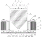
Fig. 1 is a schematic structural view of an anti-freezing evaporative cooling water chiller according to the present invention.
Detailed Description
The present invention will be described in further detail with reference to the accompanying drawings.
As shown in fig. 1, the anti-freezing evaporative cooling water chiller of the present invention includes a direct evaporative cooler, the direct evaporative cooler includes a housing 1, a water tank 15 is disposed at the bottom of an inner cavity of the housing 1, a water replenishing port 14 and a cold water outlet 16 are disposed on a side wall of the housing 1 corresponding to the water tank 15, and the water replenishing port 14 is located above the cold water outlet 16. The water tank is characterized in that a filler 6 is arranged in the shell 1 above the water tank 15, a spray pipe 5 is arranged in the shell 1 above the filler 6, the spray pipe 5 is connected with a water return pipe 4, one end of the water return pipe 4 penetrates through the shell 1 to extend out, and the water return pipe 4 is fixedly and hermetically connected with the shell 1. There are two air outlets 2 at 1 top of shell, all have fan 3 in the air outlet 2. An air inlet pipe 18 extending outwards is arranged on one group of parallel side walls of the shell 1, the air inlet pipes 18 are internally provided with indirect evaporative coolers 7, and the air inlet pipes 18 between the indirect evaporative coolers 7 and the shell 1 are internally provided with surface coolers 17. The medium in the surface cooler 17 is ethylene glycol aqueous solution, a circulating pipeline 8 is arranged between a medium inlet and a medium outlet of the surface cooler 17, a circulating pump 9 is arranged on the circulating pipeline 8, the circulating pipeline 8 comprises a heat exchange section 8-1, and the heat exchange section 8-1 of the circulating pipeline 8 is positioned in a water tank 15. And a balance port 13 and a sewage discharge port 19 are arranged on the side wall of the shell 1 corresponding to the water tank 15, the height of the balance port 13 is the same as that of the water outlet, and the sewage discharge port 19 is positioned below the water outlet.
In order to improve the heat exchange efficiency, the periphery of the upper part of the filler 6 is tightly connected with the inner side wall of the shell 1, the lower part of the filler 6 is conical, the diameter of the filler is gradually reduced from top to bottom, and the lower part of the filler 6 extends downwards to the inner cavity of the section of the shell 1 between the two air inlet pipes 18.
In order to improve the heat exchange efficiency, the heat exchange section 8-1 of the circulating pipeline 8 is a coiled pipe.
The circulating pipe is connected with a liquid inlet pipe 10 and a liquid outlet pipe 12, one ends of the liquid inlet pipe 10 and the liquid outlet pipe 12, far away from the circulating pipeline 8, penetrate through the shell 1 and extend out, the liquid inlet pipe 10, the liquid outlet pipe 12 and the shell 1 are connected in a fixed and sealed mode, and the extending ends of the liquid inlet pipe 10 and the liquid outlet pipe 12 are provided with valves 11.
The anti-freezing evaporative cooling water chilling unit utilizes the ethylene glycol aqueous solution as a medium of the surface cooler 17, and the medium is internally circulated in the surface cooler 17 through the circulating pipeline 8. The freezing point of the glycol aqueous solution is low, so that the glycol aqueous solution can not be frozen in cold winter, the surface air cooler 17 can not be frozen and damaged in cold winter, and the maintenance cost of the evaporative cooling water chilling unit is greatly reduced. Meanwhile, in cold winter, the evaporative cooling water chilling unit does not need spray water, and only through the ethylene glycol circulation of the surface cooler 17, free cold sources can be provided for users needing cooling in winter.
Claims (7)
1. The anti-freezing evaporative cooling water chilling unit comprises a direct evaporative cooler, wherein the direct evaporative cooler comprises a shell (1), a water tank (15) is arranged at the bottom of an inner cavity of the shell (1), and water replenishing ports (14) and cold water outlets (16) are formed in the side wall of the shell (1) corresponding to the water tank (15); a filler (6) is arranged in the shell (1) above the water tank (15), a spray pipe (5) is arranged in the shell (1) above the filler (6), the spray pipe (5) is connected with a water return pipe (4), one end of the water return pipe (4) penetrates through the shell (1) to extend out, and the water return pipe (4) is fixedly and hermetically connected with the shell (1); an air outlet (2) is formed in the top of the shell (1), and a fan (3) is arranged in the air outlet (2); an air inlet pipe (18) extending outwards is arranged on one group of parallel side walls of the shell (1), an indirect evaporative cooler (7) is arranged in each air inlet pipe (18), and a surface cooler (17) is arranged in each air inlet pipe (18) between each indirect evaporative cooler (7) and the shell (1); the method is characterized in that a medium in the surface air cooler (17) is an ethylene glycol aqueous solution, a circulating pipeline (8) is arranged between a medium inlet and a medium outlet of the surface air cooler (17), a circulating pump (9) is arranged on the circulating pipeline (8), the circulating pipeline (8) comprises a heat exchange section (8-1), and the heat exchange section (8-1) of the circulating pipeline (8) is positioned in a water tank (15).
2. The antifreeze evaporative cooling chiller as set forth in claim 1, wherein the periphery of the upper portion of said filler (6) is tightly connected to the inner side wall of said housing (1), the lower portion of said filler (6) is tapered and its diameter decreases from top to bottom, and the lower portion of said filler (6) extends downwardly into the interior of the section of said housing (1) between said two air inlet ducts (18).
3. The evaporative cooling chiller as set forth in claim 1, characterized in that said water replenishment port (14) is located above the cold water outlet (16).
4. The antifreeze evaporative cooling chiller according to claim 1, wherein the top of the housing (1) has two of the air outlets (2), and the air outlets (2) each have a fan (3) therein.
5. The anti-freezing evaporative cooling water chiller according to claim 1, characterized in that the side wall of the housing (1) corresponding to the water tank (15) is provided with a balance port (13) and a drain outlet (19), the balance port (13) is at the same height as the water outlet, and the drain outlet (19) is positioned below the water outlet.
6. The evaporative cooling chiller as set forth in claim 1, characterized in that the heat exchange section (8-1) of the circulation duct (8) is a serpentine tube.
7. The anti-freezing evaporative cooling water chiller according to claim 1, wherein the circulation pipe is connected with a liquid inlet pipe (10) and a liquid outlet pipe (12), one ends of the liquid inlet pipe (10) and the liquid outlet pipe (12) far away from the circulation pipe (8) penetrate through the housing (1) and extend out, the liquid inlet pipe (10) and the liquid outlet pipe (12) are fixedly and hermetically connected with the housing (1), and the extending ends of the liquid inlet pipe (10) and the liquid outlet pipe (12) are provided with valves (11).
Priority Applications (1)
| Application Number | Priority Date | Filing Date | Title |
|---|---|---|---|
| CN202122960431.0U CN216557868U (en) | 2021-11-30 | 2021-11-30 | Anti-freezing evaporative cooling water chilling unit |
Applications Claiming Priority (1)
| Application Number | Priority Date | Filing Date | Title |
|---|---|---|---|
| CN202122960431.0U CN216557868U (en) | 2021-11-30 | 2021-11-30 | Anti-freezing evaporative cooling water chilling unit |
Publications (1)
| Publication Number | Publication Date |
|---|---|
| CN216557868U true CN216557868U (en) | 2022-05-17 |
Family
ID=81579214
Family Applications (1)
| Application Number | Title | Priority Date | Filing Date |
|---|---|---|---|
| CN202122960431.0U Active CN216557868U (en) | 2021-11-30 | 2021-11-30 | Anti-freezing evaporative cooling water chilling unit |
Country Status (1)
| Country | Link |
|---|---|
| CN (1) | CN216557868U (en) |
-
2021
- 2021-11-30 CN CN202122960431.0U patent/CN216557868U/en active Active
Similar Documents
| Publication | Publication Date | Title |
|---|---|---|
| CN208024642U (en) | A kind of mechanical equipment oil temperature cooling device | |
| CN212567009U (en) | Bubble disturbance indirect heating equipment | |
| CN213872984U (en) | Container refrigeration system | |
| CN111692897A (en) | Bubble disturbance indirect heating equipment | |
| CN207333151U (en) | A kind of radiator applied on ice machine | |
| CN219735664U (en) | Evaporation type condenser | |
| CN203671999U (en) | Water-consumption-free scale-free energy-saving combined condenser | |
| CN216132323U (en) | Novel high-temperature heat exchanger for ship | |
| CN215719964U (en) | Hydraulic oil heat dissipation equipment of hydraulic machine | |
| CN212407152U (en) | Compact energy-saving servo power unit | |
| CN210425557U (en) | Integrated high-low temperature water tank | |
| CN209230078U (en) | flooded heat exchanger | |
| CN220017928U (en) | A cooling system for laboratory food conditioning machine | |
| CN211650835U (en) | Composite evaporative condenser | |
| CN224032888U (en) | Intelligent self-circulation cooling hydraulic power oil tank | |
| CN220852671U (en) | Multistage pressure condenser | |
| CN223825373U (en) | Hydraulic oil tank with cooling function | |
| CN219861634U (en) | Frame electrophoresis tank temperature control system | |
| CN221776016U (en) | An underwater internal circulation cooling structure for an electric outboard motor | |
| CN221076834U (en) | Condenser | |
| CN209230079U (en) | A high-efficiency flooded heat exchanger | |
| CN210949815U (en) | Circulating cooling device for speed reducer | |
| CN110887204A (en) | Heat energy recycling device of central air conditioner | |
| CN211668064U (en) | Energy-conserving high-efficient new energy automobile water-cooled condenser | |
| CN210602873U (en) | Spray type heat exchanger for flue |
Legal Events
| Date | Code | Title | Description |
|---|---|---|---|
| GR01 | Patent grant | ||
| GR01 | Patent grant |