CN216521249U - LED lamp convenient to disassemble and capable of adjusting angle of light source - Google Patents
LED lamp convenient to disassemble and capable of adjusting angle of light source Download PDFInfo
- Publication number
- CN216521249U CN216521249U CN202121275622.7U CN202121275622U CN216521249U CN 216521249 U CN216521249 U CN 216521249U CN 202121275622 U CN202121275622 U CN 202121275622U CN 216521249 U CN216521249 U CN 216521249U
- Authority
- CN
- China
- Prior art keywords
- plate
- light source
- mounting
- led lamp
- angle
- Prior art date
- Legal status (The legal status is an assumption and is not a legal conclusion. Google has not performed a legal analysis and makes no representation as to the accuracy of the status listed.)
- Expired - Fee Related
Links
- 241001465382 Physalis alkekengi Species 0.000 claims abstract description 13
- 238000009434 installation Methods 0.000 claims description 13
- 238000003466 welding Methods 0.000 claims description 4
- 238000000034 method Methods 0.000 abstract description 5
- 230000008569 process Effects 0.000 abstract description 5
- 230000006872 improvement Effects 0.000 description 2
- 230000009286 beneficial effect Effects 0.000 description 1
- 230000008859 change Effects 0.000 description 1
- 229910052736 halogen Inorganic materials 0.000 description 1
- 150000002367 halogens Chemical class 0.000 description 1
- 238000005286 illumination Methods 0.000 description 1
- 238000012986 modification Methods 0.000 description 1
- 230000004048 modification Effects 0.000 description 1
- 238000006467 substitution reaction Methods 0.000 description 1
Images

Landscapes
- Non-Portable Lighting Devices Or Systems Thereof (AREA)
- Fastening Of Light Sources Or Lamp Holders (AREA)
Abstract
The utility model belongs to the technical field of LED lamps, and particularly relates to an LED lamp which is convenient to disassemble and can adjust the angle of a light source. This LED lamps and lanterns convenient to dismantle and adjustable light source angle possesses the function of adjusting the light source angle, can adjust lamps and lanterns according to consumer's demand, and the dismantlement process is simple convenient, is convenient for overhaul and maintain lamps and lanterns.
Description
Technical Field
The utility model relates to the technical field of LED lamps, in particular to an LED lamp which is convenient to disassemble and can adjust the angle of a light source.
Background
The lamp is a general name of lighting tools, and is visible everywhere in daily life of people, and the lamps are various, including incandescent lamps, fluorescent lamps, halogen lamps, LED lamps and the like, wherein the LED lamps have simple structure and low cost, and along with the improvement of technical maturity, the advantages of the LED lamps are more obvious compared with other traditional lamps, so that the LED lamps are widely applied.
The LED lamps and lanterns are closely related with people's daily life, social economy's development and people's standard of living's improvement, people also are higher and higher to the requirement of illumination, the demand of people to the angle of light source also is different in time, occasion of difference, however present LED lamps and lanterns do not possess the function of adjusting the light source angle, can't satisfy part consumer's demand, and present LED lamps and lanterns dismantlement process is comparatively complicated, the not convenient to use person overhauls and maintains lamps and lanterns, the practicality of device has been reduced.
Aiming at the problems, innovative design is urgently needed on the basis of the original LED lamp.
SUMMERY OF THE UTILITY MODEL
The utility model aims to provide an LED lamp which is convenient to disassemble and can adjust the angle of a light source, and the LED lamp is used for solving the problems that the existing LED lamp provided in the background art does not have the function of adjusting the angle of the light source, cannot meet the requirements of part of consumers, is complex in disassembling process and is inconvenient for users to overhaul and maintain the lamp.
In order to achieve the purpose, the utility model provides the following technical scheme: the utility model provides a LED lamps and lanterns convenient to dismantle and adjustable light source angle, includes LED body and fixed plate, the top of LED body is connected with power source, and power source's the outside is provided with the mounting panel, the connecting axle is installed to the top of mounting panel, and the top of connecting axle is connected with the lifter, the intermediate position of lifter is provided with the hydrovalve, and the top of hydrovalve installs the connecting plate, the fixed plate is installed in the top of LED body, and the inside of fixed plate is provided with the connecting bolt, the below of connecting bolt is provided with the installation stand, and the surface of installation stand is provided with the connecting sleeve, the connecting rod is installed to the both sides of connecting sleeve, and the below of connecting rod is connected with the connecting piece, the intermediate position of connecting piece is provided with the pivot, and the top of pivot is connected with the motor.
Preferably, be the block connection between LED body and the mounting panel, and be welded connection between mounting panel and the connecting axle.
Preferably, a lifting installation structure is formed between the installation plate and the connecting plate through a lifting rod, and a rotating installation structure is formed between the lifting rod and the installation plate through a connecting shaft.
Preferably, the connecting bolts are distributed above the fixing plate at equal angles, and the fixing plate is connected with the mounting upright posts in a welding manner.
Preferably, a rotary mounting structure is formed between the mounting upright post and the connecting plate through a rotary shaft, and the rotary shaft is connected with the connecting plate in a clamping manner.
Preferably, the number of the connecting rods is 2 symmetrically arranged about the axis of the connecting sleeve, and the connecting sleeve is tightly attached to the mounting upright post.
Compared with the prior art, the utility model has the beneficial effects that: the LED lamp convenient to disassemble and capable of adjusting the angle of the light source has the function of adjusting the angle of the light source, can adjust the lamp according to the requirements of consumers, is simple and convenient in the disassembling process, and is convenient for a user to overhaul and maintain the lamp;
1. when the LED lamp which is convenient to disassemble and can adjust the angle of the light source is used, firstly, the device is installed on the top of a wall by using the connecting bolt on the fixed plate, then, the power interface is switched on, and the device can be used;
2. mounting panel and fixed plate are connected to the connecting plate, and the top of connecting plate is connected with the motor through the pivot, the accessible pivot drives the connecting plate and rotates after the motor starts, and the top of connecting plate is provided with the connecting piece, the connecting piece passes through the connecting rod and is connected with the connecting sleeve, when making the pivot drive connecting plate pivoted, the connecting piece passes through the connecting sleeve with crossing the connecting rod and rotates on the installation stand, when the lamps and lanterns of being convenient for shine the angle change, can remain the stability of lamps and lanterns all the time, the lamps and lanterns of being convenient for use, and when dismantling lamps and lanterns, lift the connecting bolt off and can accomplish the dismantlement, the practicality of device has been improved.
Drawings
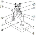
FIG. 1 is a schematic overall perspective view of the present invention;
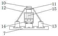
FIG. 2 is a schematic view of the overall front cross-sectional structure of the present invention;
FIG. 3 is a schematic view of the connection structure of the connection plate and the mounting plate according to the present invention.
In the figure: 1. an LED body; 2. a power interface; 3. mounting a plate; 4. a connecting shaft; 5. a lifting rod; 6. a hydraulic valve; 7. a connecting plate; 8. a fixing plate; 9. connecting a bolt; 10. mounting the upright post; 11. a connecting sleeve; 12. a connecting rod; 13. a connecting member; 14. a rotating shaft; 15. an electric motor.
Detailed Description
The technical solutions in the embodiments of the present invention will be clearly and completely described below with reference to the drawings in the embodiments of the present invention, and it is obvious that the described embodiments are only a part of the embodiments of the present invention, and not all of the embodiments. All other embodiments, which can be derived by a person skilled in the art from the embodiments given herein without making any creative effort, shall fall within the protection scope of the present invention.
Referring to fig. 1-3, the present invention provides a technical solution: an LED lamp convenient to disassemble and capable of adjusting light source angles comprises an LED body 1, a power supply interface 2, a mounting plate 3, a connecting shaft 4, a lifting rod 5, a hydraulic valve 6, a connecting plate 7, a fixing plate 8, a connecting bolt 9, a mounting upright post 10, a connecting sleeve 11, a connecting rod 12, a connecting piece 13, a rotating shaft 14 and a motor 15, wherein the power supply interface 2 is connected above the LED body 1, the mounting plate 3 is arranged outside the power supply interface 2, the connecting shaft 4 is mounted above the mounting plate 3, the lifting rod 5 is connected above the connecting shaft 4, the hydraulic valve 6 is arranged in the middle of the lifting rod 5, the connecting plate 7 is mounted above the hydraulic valve 6, the fixing plate 8 is mounted above the LED body 1, the connecting bolt 9 is arranged inside the fixing plate 8, the mounting upright post 10 is arranged below the connecting bolt 9, and the connecting sleeve 11 is arranged on the surface of the mounting upright post 10, connecting rods 12 are arranged on two sides of the connecting sleeve 11, a connecting piece 13 is connected below the connecting rods 12, a rotating shaft 14 is arranged in the middle of the connecting piece 13, and a motor 15 is connected above the rotating shaft 14;
furthermore, the LED body 1 is connected with the mounting plate 3 in a clamping manner, the mounting plate 3 is connected with the connecting shaft 4 in a welding manner, the mounting plate 3 is used for mounting the LED body 1, and a power interface 2 is arranged above the LED body 1 to supply power to the LED body 1;
furthermore, a lifting mounting structure is formed between the mounting plate 3 and the connecting plate 7 through the lifting rod 5, a rotating mounting structure is formed between the lifting rod 5 and the mounting plate 3 through the connecting shaft 4, the hydraulic valve 6 can control the lifting rod 5 to drive the mounting plate 3 to lift below the connecting plate 7, and the mounting plate 3 can rotate at a certain angle through the connecting shaft 4 through the height difference of the two lifting rods 5, so that the irradiation angle of the lamp can be changed;
furthermore, the connecting bolts 9 are distributed above the fixing plate 8 at equal angles, the fixing plate 8 is in welded connection with the mounting upright post 10, the connecting bolts 9 are used for fixing the mounting fixing plate 8 on the top of the wall, and the fixing plate 8 is connected with the device through the mounting upright post 10, so that the device is convenient to mount;
furthermore, a rotating installation structure is formed between the installation upright post 10 and the connecting plate 7 through a rotating shaft 14, the rotating shaft 14 is connected with the connecting plate 7 in a clamping manner, and the motor 15 can drive the rotating shaft 14 to rotate after being started, so that the rotating shaft 14 drives the connecting plate 7 to rotate, and the light source can be conveniently adjusted;
further, the connecting rod 12 is provided with 2 about the axis symmetry of connecting sleeve 11, and is closely laminated between connecting sleeve 11 and the installation stand 10, and connecting rod 12 passes through connecting sleeve 11 and connecting piece 13 and connects installation stand 10 and connecting plate 7, is convenient for maintain the balance of connecting plate 7, and the connecting plate 7 of being convenient for rotates simultaneously.
The working principle is as follows: when the LED lamp convenient to disassemble and capable of adjusting the angle of the light source is used, firstly, the device is installed on the top of a wall by using the connecting bolt 9 on the fixing plate 8, then, the power interface 2 is connected with a power supply to start using the device, if the angle of the light source needs to be adjusted in the using process of the device, the lifting rods 5 can be controlled by the hydraulic valve 6 to lift, the mounting plate 3 can rotate at a certain angle through the connecting shaft 4 by virtue of the height difference between the two lifting rods 5, so that the irradiation angle of the lamp is changed, the connecting plate 7 is connected with the mounting plate 3 and the fixing plate 8, the upper part of the connecting plate 7 is connected with the motor 15 through the rotating shaft 14, the connecting plate 7 can be driven to rotate by the rotating shaft 14 after the motor 15 is started, the connecting piece 13 is arranged above the connecting plate 7, the connecting piece 13 is connected with the connecting sleeve 11 through the connecting rod 12, so that the connecting plate 7 is driven to rotate by the rotating shaft 14, the connecting piece 13 and the connecting rod 12 rotate on the mounting upright post 10 through the connecting sleeve 11, so that the lamp irradiation angle can be changed conveniently, the stability of the lamp can be kept all the time, the lamp can be used conveniently, the connecting bolt 9 is detached to finish the detachment when the lamp is detached, and the practicability of the device is improved.
Finally, it should be noted that the above-mentioned contents are only used for illustrating the technical solutions of the present invention, and not for limiting the protection scope of the present invention, and that the simple modifications or equivalent substitutions of the technical solutions of the present invention by those of ordinary skill in the art can be made without departing from the spirit and scope of the technical solutions of the present invention.
Claims (6)
1. The utility model provides a LED lamps and lanterns convenient to dismantle and adjustable light source angle, includes LED body (1) and fixed plate (8), its characterized in that: the LED lamp is characterized in that a power interface (2) is connected above the LED body (1), a mounting plate (3) is arranged on the outer side of the power interface (2), a connecting shaft (4) is installed above the mounting plate (3), a lifting rod (5) is connected above the connecting shaft (4), a hydraulic valve (6) is arranged at the middle position of the lifting rod (5), a connecting plate (7) is installed above the hydraulic valve (6), a fixing plate (8) is installed above the LED body (1), a connecting bolt (9) is arranged inside the fixing plate (8), an installation upright post (10) is arranged below the connecting bolt (9), a connecting sleeve (11) is arranged on the surface of the installation upright post (10), connecting rods (12) are installed on two sides of the connecting sleeve (11), a connecting piece (13) is connected below the connecting rods (12), a rotating shaft (14) is arranged at the middle position of the connecting piece (13), and a motor (15) is connected above the rotating shaft (14).
2. The LED lamp convenient to detach and capable of adjusting the angle of the light source as claimed in claim 1, wherein: the LED lamp is characterized in that the LED body (1) is connected with the mounting plate (3) in a clamping manner, and the mounting plate (3) is connected with the connecting shaft (4) in a welding manner.
3. The LED lamp convenient to detach and capable of adjusting the angle of the light source as claimed in claim 1, wherein: constitute lift mounting structure through lifter (5) between mounting panel (3) and connecting plate (7), and constitute through connecting axle (4) between lifter (5) and mounting panel (3) and rotate mounting structure.
4. The LED lamp convenient to detach and capable of adjusting the angle of the light source as claimed in claim 1, wherein: the connecting bolts (9) are distributed above the fixing plate (8) at equal angles, and the fixing plate (8) is connected with the mounting upright post (10) in a welding manner.
5. The LED lamp convenient to detach and capable of adjusting the angle of the light source as claimed in claim 1, wherein: the mounting upright post (10) and the connecting plate (7) form a rotary mounting structure through a rotating shaft (14), and the rotating shaft (14) is connected with the connecting plate (7) in a clamping manner.
6. The LED lamp convenient to detach and capable of adjusting the angle of the light source as claimed in claim 1, wherein: the connecting rods (12) are symmetrically arranged about the axis of the connecting sleeve (11) in number of 2, and the connecting sleeve (11) is tightly attached to the mounting upright post (10).
Priority Applications (1)
| Application Number | Priority Date | Filing Date | Title |
|---|---|---|---|
| CN202121275622.7U CN216521249U (en) | 2021-06-08 | 2021-06-08 | LED lamp convenient to disassemble and capable of adjusting angle of light source |
Applications Claiming Priority (1)
| Application Number | Priority Date | Filing Date | Title |
|---|---|---|---|
| CN202121275622.7U CN216521249U (en) | 2021-06-08 | 2021-06-08 | LED lamp convenient to disassemble and capable of adjusting angle of light source |
Publications (1)
| Publication Number | Publication Date |
|---|---|
| CN216521249U true CN216521249U (en) | 2022-05-13 |
Family
ID=81460818
Family Applications (1)
| Application Number | Title | Priority Date | Filing Date |
|---|---|---|---|
| CN202121275622.7U Expired - Fee Related CN216521249U (en) | 2021-06-08 | 2021-06-08 | LED lamp convenient to disassemble and capable of adjusting angle of light source |
Country Status (1)
| Country | Link |
|---|---|
| CN (1) | CN216521249U (en) |
-
2021
- 2021-06-08 CN CN202121275622.7U patent/CN216521249U/en not_active Expired - Fee Related
Similar Documents
| Publication | Publication Date | Title |
|---|---|---|
| CN202858237U (en) | Table with light | |
| CN205957035U (en) | Landscape street lamp | |
| CN206488214U (en) | A kind of dual-purpose LED wall lamp | |
| CN212361729U (en) | Stage lamp with good protection performance | |
| CN206093790U (en) | Rotatory street lamp of LED view | |
| CN2411417Y (en) | Lifting street lamp | |
| CN210568103U (en) | LED lamp for outdoor lawn | |
| CN213453425U (en) | Multifunctional street lamp convenient to energy-saving control | |
| CN206754904U (en) | The desk lamp and illuminator of detachable outer cover | |
| CN201262327Y (en) | Electric torch used as desk lamp | |
| CN208025342U (en) | A kind of landscape design Landscape Lamp convenient for adjusting | |
| CN208886463U (en) | A kind of portable lamp | |
| CN207880706U (en) | A kind of new energy source energy-saving street lamp | |
| CN223636084U (en) | Foldable lamp post | |
| CN200958693Y (en) | A wide-angle projection lamp | |
| CN212750296U (en) | Safety emergency indicator lamp | |
| CN109458593A (en) | A kind of energy-saving environment-friendly road lamp of chain type lifting solar panels | |
| CN207112464U (en) | A kind of height-adjustable desk lamp | |
| CN216346138U (en) | LED lamp with mount | |
| CN209839883U (en) | Novel street lamp of town road | |
| CN216438918U (en) | Clothing show shelf with show light | |
| CN209042170U (en) | A kind of garden LED light | |
| CN217952124U (en) | Multipurpose solar lamp | |
| CN216244018U (en) | Joint control solar lamp control adjustment mechanism | |
| CN211232656U (en) | LED street lamp |
Legal Events
| Date | Code | Title | Description |
|---|---|---|---|
| GR01 | Patent grant | ||
| GR01 | Patent grant | ||
| CF01 | Termination of patent right due to non-payment of annual fee |
Granted publication date: 20220513 |
|
| CF01 | Termination of patent right due to non-payment of annual fee |