CN216509598U - Hot sealing knife device - Google Patents
Hot sealing knife device Download PDFInfo
- Publication number
- CN216509598U CN216509598U CN202122524150.0U CN202122524150U CN216509598U CN 216509598 U CN216509598 U CN 216509598U CN 202122524150 U CN202122524150 U CN 202122524150U CN 216509598 U CN216509598 U CN 216509598U
- Authority
- CN
- China
- Prior art keywords
- plate
- assembly
- cutter
- hot
- connecting seat
- Prior art date
- Legal status (The legal status is an assumption and is not a legal conclusion. Google has not performed a legal analysis and makes no representation as to the accuracy of the status listed.)
- Active
Links
- 238000007789 sealing Methods 0.000 title claims abstract description 24
- 239000007779 soft material Substances 0.000 claims description 32
- 238000010438 heat treatment Methods 0.000 claims description 19
- 230000005540 biological transmission Effects 0.000 claims description 18
- 239000003638 chemical reducing agent Substances 0.000 claims description 12
- VYPSYNLAJGMNEJ-UHFFFAOYSA-N Silicium dioxide Chemical compound O=[Si]=O VYPSYNLAJGMNEJ-UHFFFAOYSA-N 0.000 claims description 4
- 239000000741 silica gel Substances 0.000 claims description 4
- 229910002027 silica gel Inorganic materials 0.000 claims description 4
- 238000000034 method Methods 0.000 claims 1
- 239000012785 packaging film Substances 0.000 abstract description 26
- 229920006280 packaging film Polymers 0.000 abstract description 26
- 238000004806 packaging method and process Methods 0.000 abstract description 11
- 239000000463 material Substances 0.000 abstract description 8
- 230000000694 effects Effects 0.000 description 6
- 238000009434 installation Methods 0.000 description 5
- 230000015572 biosynthetic process Effects 0.000 description 4
- 206010053615 Thermal burn Diseases 0.000 description 3
- 238000000605 extraction Methods 0.000 description 3
- 239000002184 metal Substances 0.000 description 3
- 239000013070 direct material Substances 0.000 description 2
- 238000006073 displacement reaction Methods 0.000 description 2
- 230000009977 dual effect Effects 0.000 description 2
- 239000003292 glue Substances 0.000 description 2
- 239000012528 membrane Substances 0.000 description 2
- 230000002093 peripheral effect Effects 0.000 description 2
- 230000002035 prolonged effect Effects 0.000 description 2
- 230000009286 beneficial effect Effects 0.000 description 1
- 238000009835 boiling Methods 0.000 description 1
- 230000007547 defect Effects 0.000 description 1
- 238000010409 ironing Methods 0.000 description 1
- 238000003754 machining Methods 0.000 description 1
- 239000004033 plastic Substances 0.000 description 1
Images
Landscapes
- Package Closures (AREA)
Abstract
The utility model discloses a hot sealing knife device, and relates to the technical field of packaging machinery. According to the utility model, on the basis of the original hot sealing cutter structure, the original bottom base plate is divided into the bottom plate and the flexible material plate, and the elastic thin plate is additionally arranged above the bottom base plate, when the hot sealing cutter is in actual work, the packaging film passes through the upper part of the elastic thin plate, the cutter presses the elastic thin plate when cutting the film downwards, the elastic thin plate is deformed, and the flexible material plate below the elastic thin plate is also deformed under stress, so that the contact depth between the cutter teeth of the cutter and the packaging film is adjusted, the cutting of the packaging film is more uniform, and the purpose of improving the uneven depth of the cut mark is achieved.
Description
Technical Field
The utility model relates to the technical field of packaging machinery, in particular to a hot sealing knife device.
Background
The packaging bags or packaging boxes of a plurality of products on the market at present are provided with easy-to-tear openings which are convenient for users to tear the packaging bags, and the plastic packaging bags with the paper extraction are often provided with straight-line-shaped easy-to-tear openings, but the easy-to-tear openings need to apply acting force to two sides of the packaging bags simultaneously to be opened, and the paper extraction in the packaging bags are scattered because the packaging bags are difficult to tear due to the fact that mould pressing is not in place or the paper extraction is too strong when the packaging bags are torn.
In recent years, some film bodies which are used for cutting the easy-to-tear opening into two parallel lines and tearing the end part of the easy-to-tear opening appear in the market, so that a user can tear the easy-to-tear opening completely through the film bodies directly when using the easy-to-use easy-to-tear opening, but the mould for pressing the easy-to-tear opening generally can generate errors during processing to cause the problem that the depth of a cut mark is uneven, and the easy-to-tear opening can not be torn smoothly.
The state intellectual property office in 2018 11 month 27, discloses a utility model patent that publication number is CN208148034U, the name is "easily tear a mouthful blanking mould", and this utility model includes cope match-plate pattern, lower bolster and connection fixed the cope match-plate pattern with two support posts at lower bolster both ends still including actuating mechanism, mould board, cutter group and sword groove, the sword groove sets up the upper surface center department of lower bolster, cutter group fixes the lower surface of mould board, cutter group with the sword groove is identical, actuating mechanism fixes mould board upper surface center department and with the lower surface center department of cope match-plate pattern links to each other, actuating mechanism drives the mould board for the cope match-plate pattern reciprocates. The utility model discloses an easily tear a blanking mould peripheral and be even quadrangle to need not to have too high requirement to external environment, be applicable to different current packaging machinery, the space demand is few, simultaneously because the peripheral is even, makes its installation more convenient.
Easily tear a blanking mould among the above-mentioned prior art because during blanking packaging film, generally be hard contact between cutter and the bottom plate, can lead to blanking cutter to produce the error man-hour, and then lead to the shear mark depth of blanking uneven, exist some membranes even and do not punch in place, finally lead to tearing mouthful inhomogeneous, tear the effect poor.
SUMMERY OF THE UTILITY MODEL
In order to overcome the defects and shortcomings in the prior art, the utility model provides a hot sealing knife device, and aims to solve the problem of uneven depth of a cutting mark in the prior art. According to the utility model, on the basis of the original hot sealing cutter structure, the original bottom base plate is divided into the bottom plate and the flexible material plate, and the elastic thin plate is additionally arranged above the bottom base plate, when the hot sealing cutter is in actual work, the packaging film passes through the upper part of the elastic thin plate, the cutter presses the elastic thin plate when cutting the film downwards, the elastic thin plate is deformed, and the flexible material plate below the elastic thin plate is also deformed under stress, so that the contact depth between the cutter teeth of the cutter and the packaging film is adjusted, the cutting of the packaging film is more uniform, and the purpose of improving the uneven depth of the cut mark is achieved.
In order to solve the problems in the prior art, the utility model is realized by the following technical scheme:
the hot sealing knife device comprises a mounting frame, a driving assembly, a transmission assembly, a connecting seat, a guide assembly and a cutter assembly, wherein the driving assembly is mounted on the mounting frame, the guide assembly is assembled on the mounting frame, and the driving assembly is connected with the connecting seat through the transmission assembly and drives the connecting seat to reciprocate up and down on the guide assembly; the cutter assembly is arranged at the lower end of the connecting seat; the bottom of the mounting rack is provided with a backing plate component corresponding to the working area of the cutter component, the backing plate component comprises a bottom plate and a soft material plate arranged on the bottom plate, and an elastic thin plate is further arranged on the soft material plate.
Furthermore, the cutter assembly comprises a heating plate and a hot knife, the hot knife is installed at the bottom of the heating plate, a plurality of connecting columns are arranged at the upper end of the heating plate, the connecting seats are penetrated at the upper ends of the connecting columns, limiting nuts are installed at the upper ends of the connecting columns, and springs are assembled on the connecting columns between the heating plate and the connecting seats.
Furthermore, the driving assembly comprises a servo motor, a speed reducer and an eccentric shaft sleeve, the speed reducer is connected with the servo motor, the eccentric shaft sleeve is assembled on an output shaft of the speed reducer, one end of the transmission assembly is hinged on the eccentric shaft sleeve, and the other end of the transmission assembly is hinged on the connecting seat.
The transmission assembly comprises joint bearings at two ends and a fine tooth connecting rod, wherein the two ends of the fine tooth connecting rod are connected with the joint bearings respectively.
The guide assembly comprises two linear guide rails, and the connecting seat is connected to the two linear guide rails in a sliding mode.
The bottom of the mounting frame is provided with a groove for assembling a backing plate component, and the backing plate component is embedded into the groove.
The elastic thin plate is a spring plate.
The soft material plate is a silica gel plate or a rubber plate.
Compared with the prior art, the beneficial technical effects brought by the utility model are as follows:
1. according to the utility model, on the basis of the original hot sealing cutter structure, the original bottom base plate is divided into the bottom plate and the flexible material plate, and the elastic thin plate is additionally arranged above the bottom base plate, when the hot sealing cutter is in actual work, the packaging film passes through the upper part of the elastic thin plate, the cutter presses the elastic thin plate when cutting the film downwards, the elastic thin plate is deformed, and the flexible material plate below the elastic thin plate is also deformed under stress, so that the contact depth between the cutter teeth of the cutter and the packaging film is adjusted, the cutting of the packaging film is more uniform, and the purpose of improving the uneven depth of the cut mark is achieved.
2. The base plate assembly comprises a bottom plate, a soft material plate and an elastic thin plate, wherein the elastic thin plate provides a certain hard support for a hot knife, and meanwhile, the elastic thin plate can deform and transmit the deformation to the soft material plate, so that the knife-cutting of the packaging film is more uniform. The setting of elastic sheet also plays the effect of protection soft material board simultaneously, and the cutter has certain heat, if direct and soft material board contact, can cause the damage to soft material board, and soft material board has the soft material of department to glue on the cutter after being heated simultaneously, influences the use of cutter. The utility model increases the function of the bottom plate, provides support for the soft material plate, controls the deformation of the soft material plate within a certain range, and certainly, the bottom plate can be replaced by the rigid mounting frame.
3. The cutter unit in this application includes hot plate and hot sword, is on conducting the heat to hot sword through the hot plate, then hot briquetting on the hot sword repackaging film forms and tears a mouthful impression. Set up a plurality of spliced poles between heating plate and the connecting seat in this application, prevent on the one hand that heating plate and connecting seat straight line from producing lateral shifting, and influence the formation of impression, certain guide effect is played to on the other hand spliced pole, ensures the levelness of heating plate when spliced pole axial displacement. And set up the spring between hot plate and connecting seat, when processing, the connecting seat is driven by drive assembly and is pushed down, drives the hot plate and pushes down, after the hot sword is used on the packaging film, on the one hand can make backing plate subassembly produce deformation, on the other hand spring also is compressed, under the dual elastic action of spring and backing plate subassembly, the packaging film cuts a knife more evenly, has also avoided pushing down the too big damage that causes cutter or packaging film, influences the formation of tearing a mouthful impression.
4. The utility model adopts the servo motor, the speed reducer and the eccentric shaft sleeve as the driving assembly, the speed of the driving assembly is adjustable and controllable, and the processing efficiency can be quickly adjusted according to the actual working condition.
5. The transmission assembly adopts the fine tooth connecting rod and the knuckle bearing, and threaded connection between the fine tooth connecting rod and the knuckle bearing can adjust the distance between the knuckle bearings at two ends, thereby adjusting the length of the transmission assembly, adjusting the stroke of the connecting seat in a reciprocating manner, and having wider application range.
6. According to the utility model, the mounting frame is provided with the groove for assembling the backing plate component, so that the applicability of the ironing and sealing knife device can be expanded, and the backing plate component is embedded in the groove, so that the backing plate component is flush with the upper surface of the bottom of the mounting frame on one hand, the passing of a packaging film is not influenced, and the backing plate component is convenient to replace in an embedded mounting mode on the other hand. Can also be through changing cutter unit spare and backing plate subassembly, scald this application and seal the sword device and convert cutter stamping device into, be about to heat the sword and change into the slotting tool, change the backing plate subassembly into the sword groove, the sword groove is inserted to the blade on the slotting tool, can cut out the cutter mark on the packaging film.
7. The elastic thin plate is selected from a spring plate, the soft material plate is selected from a silica gel plate or a rubber plate, the material of the elastic thin plate has good resilience, the elastic thin plate cannot deform after being used for a long time, and the service life of the hot sealing knife device is prolonged.
Drawings
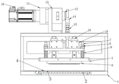
FIG. 1 is a schematic front view of a sealing knife device according to the present invention;
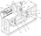
FIG. 2 is a schematic perspective view of the sealing knife device of the present invention;
reference numerals: 1. mounting bracket, 2, bottom plate, 3, soft material board, 4, elastic sheet, 5, hot plate, 6, hot sword, 7, spliced pole, 8, stop nut, 9, spring, 10, servo motor, 11, speed reducer, 12, eccentric shaft sleeve, 13, motor mount pad, 14, joint bearing, 15, thin tooth connecting rod, 16, linear guide, 17, recess, 18, connecting seat.
Detailed Description
The technical solution of the present invention is further described in detail with reference to the drawings and the specific embodiments. It is to be understood that the described embodiments are merely exemplary of the utility model, and not restrictive of the full scope of the utility model. All other embodiments, which can be derived by a person skilled in the art from the embodiments given herein without making any creative effort, shall fall within the protection scope of the present invention.
As an embodiment of the present embodiment, referring to fig. 1 of the specification, the embodiment discloses a hot sealing knife device, which includes an installation frame 1, a driving assembly, a transmission assembly, a connection seat, a guide assembly and a knife assembly, wherein the driving assembly is installed on the installation frame 1, the guide assembly is assembled on the installation frame 1, the driving assembly is connected with the connection seat through the transmission assembly, and drives the connection seat to reciprocate up and down on the guide assembly; the cutter assembly is arranged at the lower end of the connecting seat; the bottom of the mounting rack 1 is provided with a backing plate component corresponding to the working area of the cutter component, the backing plate component comprises a bottom plate 2 and a soft material plate 3 arranged on the bottom plate 2, and an elastic thin plate 4 is further arranged on the soft material plate 3. This embodiment is on original boiling hot seal sword structure basis, divide into bottom plate 2 with original bottom backing plate, soft material board 3, and install elastic sheet 4 additional above it, in the time of the actual operation, the packaging film passes from elastic sheet 4 top, press elastic sheet 4 when the cutter cuts the membrane downwards, elastic sheet 4 that is take place deformation, soft material board 3 of elastic sheet 4 below also atress produces deformation, thereby the depth of contact between the sword tooth of adjustment cutter and the packaging film, it is more even to make the packaging film eat the sword, reach and improve the purpose that the depth of cut is uneven.
Wherein, backing plate subassembly includes bottom plate 2, soft material board 3 and elastic sheet metal 4, and elastic sheet metal 4 provides certain hard support for hot sword 6, and elastic sheet metal 4 can be out of shape simultaneously, passes to soft material board 3 with its deformation on, makes the packaging film eat the sword more even. The setting of elastic sheet 4 also plays the effect of protection soft material board 3 simultaneously, and the cutter has certain heat, if direct and soft material board 3 contact, can cause the damage to soft material board 3, and soft material board 3 is heated simultaneously and has the soft material of department to glue on the cutter, influences the use of cutter. The utility model increases the function of the bottom plate 2, and provides support for the soft material plate 3, so that the deformation of the soft material plate 3 is controlled within a certain range, and the bottom plate 2 can be replaced by the rigid mounting frame 1.
As another embodiment of the present embodiment, referring to the accompanying drawings 1 and 2 of the specification, the cutter assembly includes a heating plate 5 and a hot knife 6, the hot knife 6 is installed at the bottom of the heating plate 5, the upper end of the heating plate 5 is provided with a plurality of connecting posts 7, the upper ends of the connecting posts 7 penetrate through a connecting seat, the upper ends of the connecting posts 7 are provided with limit nuts 8, and a spring 9 is assembled on the connecting posts 7 between the heating plate 5 and the connecting seat. In the embodiment, heat is transmitted to the hot knife 6 through the heating plate 5, and then the hot knife 6 is hot-pressed and molded on the packaging film to form a tearing mark. Set up a plurality of spliced poles 7 between heating plate 5 and the connecting seat in this application, prevent on the one hand that heating plate 5 and connecting seat straight line from producing lateral shifting, and influence the formation of impression, on the other hand spliced pole 7 plays certain guide effect, ensures the levelness of heating plate 5 when spliced pole 7 axial displacement. And set up spring 9 between hot plate 5 and connecting seat, when processing, the connecting seat is pushed down by drive assembly drives, drive hot plate 5 and push down, after hot sword 6 is used on the packaging film, on the one hand can make the backing plate subassembly produce deformation, on the other hand spring 9 is also compressed, under the dual elastic action of spring 9 and backing plate subassembly, the packaging film eats the sword more even, has also avoided pushing down the too big damage that causes cutter or packaging film, influences the formation of tearing a mouthful impression.
As another embodiment of this embodiment, the above-mentioned driving assembly may adopt an existing driving cylinder, the driving assembly may adopt a transmission rod or a cylinder telescopic rod, the guiding assembly may adopt a sliding rail or a guiding column, and the tool assembly may adopt the tool assembly structure in the patent document cited in the background art.
Further, as another embodiment of the present embodiment, as shown in fig. 1 and fig. 2, the driving assembly includes a servo motor 10, a reducer 11 and an eccentric bushing 12, the servo motor 10 and the reducer are mounted on the mounting frame 1 through a motor mounting base 13; the speed reducer is connected with the servo motor 10, the eccentric shaft sleeve 12 is assembled on the output shaft of the speed reducer 11, one end of the transmission assembly is hinged on the eccentric shaft sleeve 12, and the other end of the transmission assembly is hinged on the connecting seat. The speed of the machine is adjustable and controllable, and the machining efficiency can be quickly adjusted according to actual working conditions.
Further, the transmission assembly includes a knuckle bearing 14 at both ends and a fine tooth connecting rod 15 connected to the knuckle bearing 14 at both ends. Threaded connection between fine tooth connecting rod 15 and the joint bearing 14 can adjust the distance between both ends joint bearing 14 to the length of drive assembly has been adjusted, thereby the adaptability has adjusted connecting seat reciprocating motion's stroke from top to bottom, and application scope is wider. The guide assembly comprises two linear guide rails 16, and the connecting seat is connected to the two linear guide rails 16 in a sliding mode.
As a further embodiment of this embodiment, referring to the description of fig. 1, the bottom of the mounting frame is provided with a groove 17 for mounting a shim plate assembly, and the shim plate assembly is embedded in the groove 17. This embodiment is provided with the recess of assembly backing plate subassembly on the mounting bracket, and the purpose that sets up like this can be extended this application scalds the suitability of sealing the sword device, with the embedded installation of backing plate subassembly in the recess, makes backing plate subassembly and mounting bracket bottom upper surface parallel and level on the one hand, does not influence passing through of packaging film, and the embedded mounting means of on the other hand also is convenient for change the backing plate subassembly. Can also be through changing cutter unit spare and backing plate subassembly, scald this application and seal the sword device and convert cutter stamping device into, be about to heat the sword and change into the slotting tool, change the backing plate subassembly into the sword groove, the sword groove is inserted to the blade on the slotting tool, can cut out the cutter mark on the packaging film.
As another embodiment of this embodiment, the elastic thin plate 4 is a spring plate or other elastic plate with certain hardness. The soft material plate 3 is a silica gel plate, a rubber plate or other soft material plates. The material of the hot sealing knife device has good resilience, and the hot sealing knife device cannot deform after being used for a long time, so that the service life of the hot sealing knife device is prolonged.
Claims (8)
1. The hot sealing knife device comprises a mounting frame (1), a driving assembly, a transmission assembly, a connecting seat, a guide assembly and a cutter assembly, wherein the driving assembly is mounted on the mounting frame (1), the guide assembly is assembled on the mounting frame (1), and the driving assembly is connected with the connecting seat through the transmission assembly and drives the connecting seat to reciprocate up and down on the guide assembly; the cutter assembly is arranged at the lower end of the connecting seat; the method is characterized in that: the bottom of the mounting rack (1) is provided with a backing plate component corresponding to the working area of the cutter component, the backing plate component comprises a bottom plate (2) and a soft material plate (3) arranged on the bottom plate (2), and an elastic thin plate (4) is further arranged on the soft material plate (3).
2. A hot seal knife assembly as defined in claim 1, wherein: the cutter assembly comprises a heating plate (5) and a hot knife (6), the hot knife (6) is installed at the bottom of the heating plate (5), a plurality of connecting columns (7) are arranged at the upper end of the heating plate (5), the connecting seats are penetrated at the upper ends of the connecting columns (7), limit nuts (8) are installed at the upper ends of the connecting columns (7), and springs (9) are assembled on the connecting columns (7) between the heating plate (5) and the connecting seats.
3. A press-sealing knife device as claimed in claim 1 or 2, characterized in that: the driving assembly comprises a servo motor (10), a speed reducer (11) and an eccentric shaft sleeve (12), the speed reducer is connected with the servo motor (10), the eccentric shaft sleeve (12) is assembled on an output shaft of the speed reducer (11), one end of the transmission assembly is hinged to the eccentric shaft sleeve (12), and the other end of the transmission assembly is hinged to the connecting seat.
4. A press knife assembly as claimed in claim 1 or claim 2, in which: the transmission assembly comprises joint bearings (14) at two ends and a fine tooth connecting rod (15) with two ends respectively connected with the joint bearings (14).
5. A press-sealing knife device as claimed in claim 1 or 2, characterized in that: the guide assembly comprises two linear guide rails (16), and the connecting seat is connected to the two linear guide rails (16) in a sliding mode.
6. A hot seal knife assembly as defined in claim 1, wherein: the bottom of the mounting rack is provided with a groove (17) for assembling a backing plate component, and the backing plate component is embedded into the groove (17).
7. A hot seal knife apparatus as claimed in claim 1, 2 or 6, wherein: the elastic thin plate (4) is a spring plate.
8. A hot seal knife apparatus as claimed in claim 1, 2 or 6, wherein: the soft material plate (3) is a silica gel plate or a rubber plate.
Priority Applications (1)
| Application Number | Priority Date | Filing Date | Title |
|---|---|---|---|
| CN202122524150.0U CN216509598U (en) | 2021-10-20 | 2021-10-20 | Hot sealing knife device |
Applications Claiming Priority (1)
| Application Number | Priority Date | Filing Date | Title |
|---|---|---|---|
| CN202122524150.0U CN216509598U (en) | 2021-10-20 | 2021-10-20 | Hot sealing knife device |
Publications (1)
| Publication Number | Publication Date |
|---|---|
| CN216509598U true CN216509598U (en) | 2022-05-13 |
Family
ID=81522467
Family Applications (1)
| Application Number | Title | Priority Date | Filing Date |
|---|---|---|---|
| CN202122524150.0U Active CN216509598U (en) | 2021-10-20 | 2021-10-20 | Hot sealing knife device |
Country Status (1)
| Country | Link |
|---|---|
| CN (1) | CN216509598U (en) |
Cited By (1)
| Publication number | Priority date | Publication date | Assignee | Title |
|---|---|---|---|---|
| CN117585256A (en) * | 2023-12-25 | 2024-02-23 | 红云红河烟草(集团)有限责任公司 | Cigarette pack shaping equipment |
-
2021
- 2021-10-20 CN CN202122524150.0U patent/CN216509598U/en active Active
Cited By (1)
| Publication number | Priority date | Publication date | Assignee | Title |
|---|---|---|---|---|
| CN117585256A (en) * | 2023-12-25 | 2024-02-23 | 红云红河烟草(集团)有限责任公司 | Cigarette pack shaping equipment |
Similar Documents
| Publication | Publication Date | Title |
|---|---|---|
| CN108162098A (en) | A kind of glued board automatic Mosaic machine | |
| CN214639684U (en) | Sheet metal stamping die with positioning function | |
| CN110126020B (en) | Mask cutting device | |
| CN220331451U (en) | Cutter holder device of die cutting machine | |
| CN201346864Y (en) | Powder feeding device of powder press | |
| CN220717469U (en) | Stamping equipment is used in bottle lid production | |
| CN212919619U (en) | Paper cutter with buffer device | |
| CN215241289U (en) | Trade mark die-cutting machine | |
| CN211439004U (en) | Spacing-adjustable follow-up presser foot assembly | |
| CN208290046U (en) | Die cutting plate shifts regulating mechanism | |
| CN207027714U (en) | An automatic full-section and half-section slicing mechanism for a circular knife slitting machine | |
| CN208035648U (en) | Concave-convex hot stamping die cutting all-in-one machine | |
| CN220035011U (en) | Cutting machine convenient to adjust cloth and decide length | |
| CN207593976U (en) | The continuous material pulling mechanism of die-cutting machine | |
| CN222932889U (en) | Double-station die cutting machine | |
| CN220591351U (en) | Continuous stamping forming device for guide ring | |
| CN114670286B (en) | Rubber self-positioning anti-offset mechanism | |
| CN223173671U (en) | Packaging carton blanking device | |
| CN220922695U (en) | Multi-servo independent adjustment quadruple die cutting mechanism | |
| CN218365239U (en) | Beer machine is used in cardboard processing | |
| CN214394305U (en) | Self-shearing packaging printing machine | |
| CN219882682U (en) | Stamping plate capable of preventing stripping for rubber gasket die cutting machine | |
| CN218255609U (en) | A silicone pad blanking jig | |
| CN223236522U (en) | Cutter guiding mechanism based on cross cutting machine | |
| CN219255823U (en) | Convenient-to-adjust cutting and pressing mechanism |
Legal Events
| Date | Code | Title | Description |
|---|---|---|---|
| GR01 | Patent grant | ||
| GR01 | Patent grant |