Mould of many convex closure of high-precision molding on silk screen
Technical Field
The utility model relates to the technical field of convex hull product molding, in particular to a mold for high-precision molding of multiple convex hulls on a silk screen.
Background
The silk screen is distributed with a plurality of circular holes which are closely arranged, technologically, a convex hull product as shown in figures 1-2 is required to be molded on the silk screen, and a plurality of convex hulls 21 are molded on the convex hull product. At present, the convex hull product is formed in one step by using a forming die, wherein the forming die comprises an upper die and a lower die, a plurality of female die inserts are arranged in the upper die, a plurality of male die inserts are arranged in the lower die, the male die inserts and the female die inserts are arranged in an opposite mode, during forming, a strip-shaped silk screen is placed on the top surface of the male die inserts, then the upper die is moved downwards, and after the die is closed, each female die insert and the female die inserts are matched, so that a plurality of convex hulls 21 are formed on the silk screen. However, although the forming mold can form a convex hull product, after forming, it is found that the circular hole on the convex hull in the middle becomes quite large, the structure of the convex hull in the middle is as shown in fig. 3, the convex hull product cannot meet the requirements of customers, and the reason for generating the unqualified convex hull is that the material around the convex hull in the middle cannot shrink towards the middle part, so that the mesh becomes large and serious. Therefore, a mold for improving the quality of the convex hull and the quality of the convex hull product is needed.
SUMMERY OF THE UTILITY MODEL
The utility model aims to overcome the defects of the prior art and provide the die for high-precision molding of the multiple convex hulls on the silk screen, which has a compact structure, improves the convex hull molding quality and improves the convex hull product quality.
The purpose of the utility model is realized by the following technical scheme: a die for high-precision forming of a multi-convex hull on a silk screen comprises an upper die and a lower die, wherein the lower die comprises a lower cushion plate and a concave die plate which are fixedly integrated from bottom to top, a vertical spring is arranged in the lower cushion plate, the top of the vertical spring is connected with a force transmission column, the force transmission column extends into a concave cavity of the concave die plate, a top plate which is slidably arranged in the concave cavity is fixedly arranged on an extending end, the top surface of the top plate extends above the concave die plate, a guide seat which is arranged in the concave cavity and is positioned right below the top plate is fixedly arranged at the bottom of the concave cavity, a middle spring and side springs which are respectively arranged on the left side and the right side of the middle spring are arranged in the lower cushion plate, the middle spring and the two side springs penetrate through the guide seat and extend into the concave cavity, a middle convex die insert is fixedly arranged at the top of the middle spring, first side convex die inserts are fixedly arranged at the tops of the two side springs, and the middle convex die insert and the two first side convex dies extend into the top plate, second side male die inserts are fixedly arranged on the top surface of the guide seat and positioned on the outer side of the first side male die insert, the two second side male die inserts extend into the top plate, the height of the middle male die insert is larger than that of the first side male die insert, and the height of the first side male die insert is larger than that of the second side male die insert;
go up the mould and set firmly in integrative upper padding plate and stripper from top to bottom in order, the upper padding plate internal stability has set firmly the cushion, is provided with in the stripper and presses the material mold insert, has set firmly a plurality of die mold inserts corresponding with the terrace die mold insert on the basal surface of cushion, and the die mold insert stretches into in pressing the material mold insert, still has set firmly the prepressing rod on the cushion, and the setting of stripper is run through downwards to the prepressing rod, and the prepressing rod sets up directly over the roof.
The two first side male die inserts are arranged in a bilateral symmetry mode relative to the middle male die insert, and the two second side male die inserts are arranged in a bilateral symmetry mode relative to the middle male die insert.
And the bottom of the lower backing plate is fixedly provided with a base.
And an upper support is fixedly arranged at the top of the upper backing plate.
The diameters of the top end parts of the middle convex die insert, the first side convex die insert and the second side convex die insert are equal.
The diameters of the die inserts are equal.
The utility model has the following advantages: the convex hull forming quality and the convex hull product quality are improved.
Drawings
FIG. 1 is a schematic view of a convex hull product;
FIG. 2 is a top view of FIG. 1;
FIG. 3 is a schematic structural diagram of a formed convex middle hull;
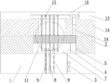
FIG. 4 is a schematic structural view of the present invention;
FIG. 5 is a schematic view of a shaped convex central lobe;
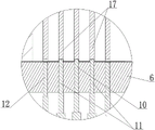
FIG. 6 is an enlarged view of a portion I of FIG. 5;
FIG. 7 is a schematic structural diagram of a molded semi-finished product A;
FIG. 8 is a top view of FIG. 7;
FIG. 9 is a schematic view of a shaped first side convex hull;
FIG. 10 is an enlarged partial view of section II of FIG. 9;
FIG. 11 is a schematic structural view of a molded semi-finished product B;
FIG. 12 is a top view of FIG. 11;
FIG. 13 is a schematic view of a molded convex hull product;
FIG. 14 is an enlarged partial view of section III of FIG. 13;
in the figure, 1-lower backing plate, 2-concave template, 3-vertical spring, 4-force transfer column, 5-concave cavity, 6-top plate, 7-guide seat, 8-middle spring, 9-side spring, 10-middle convex mold insert, 11-first side convex mold insert, 12-second side convex mold insert, 13-upper backing plate, 14-stripper plate, 15-pressing mold insert, 16-cushion block, 17-concave mold insert, 18-prepressing rod, 19-middle convex hull, 20-first side convex hull and 21-convex hull.
Detailed Description
The utility model will be further described with reference to the accompanying drawings, without limiting the scope of the utility model to the following:
as shown in figure 4, the die for high-precision forming of the multi-convex hull on the silk screen comprises an upper die and a lower die, wherein the lower die comprises a lower cushion plate 1 and a concave die plate 2 which are fixedly integrated from bottom to top, a vertical spring 3 is arranged in the lower cushion plate 1, the top of the vertical spring 3 is connected with a force transmission column 4, the force transmission column 4 extends into a cavity 5 of the concave die plate 2, a top plate 6 which is slidably arranged in the cavity 5 is fixedly arranged on an extending end, the top surface of the top plate 6 extends above the concave die plate 2, a guide seat 7 which is arranged in the cavity 5 and is positioned right below the top plate 6 is fixedly arranged in the bottom of the cavity 5, a middle spring 8 and side springs 9 which are respectively arranged on the left side and the right side of the middle spring 8 are arranged in the lower cushion plate 1, the middle spring 8 and the two side springs 9 both penetrate through the guide seat 7 and extend into the cavity 5, a middle convex die insert 10 is fixedly arranged on the top of the middle spring 8, first side convex die inserts 11 are fixedly arranged on the top of the two side springs 9, the middle male die insert 10 and the two first side male die inserts 11 extend into the top plate 6, the second side male die inserts 12 are fixedly arranged on the top surface of the guide seat 7 and located on the outer sides of the first side male die inserts 11, the two second side male die inserts 12 extend into the top plate 6, the height of the middle male die insert 10 is larger than that of the first side male die inserts 11, and the height of the first side male die inserts 11 is larger than that of the second side male die inserts 12.
The upper die comprises an upper backing plate 13 and a discharging plate 14 which are sequentially and fixedly arranged on the upper backing plate 13 from top to bottom, a cushion block 16 is fixedly arranged in the upper backing plate 13, a material pressing insert 15 is arranged in the discharging plate 14, a plurality of female die inserts 17 corresponding to the male die inserts are fixedly arranged on the bottom surface of the cushion block 16, the diameters of the female die inserts 17 are equal, the female die inserts 17 stretch into the material pressing insert 15, a pre-pressing rod 18 is further fixedly arranged on the cushion block 16, the discharging plate 14 is downwards penetrated through the pre-pressing rod 18, and the pre-pressing rod 18 is arranged right above the top plate 6.
The two first side male die inserts 11 are arranged in a bilateral symmetry mode about the middle male die insert 10, the two second side male die inserts 12 are arranged in a bilateral symmetry mode about the middle male die insert 10, and the bottom of the lower backing plate 1 is fixedly provided with a base. The top of the upper backing plate 13 is fixedly provided with an upper support, and the diameters of the top end parts of the middle male die insert 10, the first side male die insert 11 and the second side male die insert 12 are equal.
The method for forming the multi-convex hull on the silk screen by the mould in a high-precision manner comprises the following steps:
s1, connecting the upper support to a stamping head of a stamping die;
s2, placing the strip-shaped wire mesh on the top surface of the top plate 6;
s3, controlling a stamping head of the stamping die to move downwards, driving an upper support to move downwards by the stamping head, and driving an upper backing plate 13, a stripper plate 14, a pre-pressing rod 18 and a female die insert 17 to move downwards synchronously by the upper support;
s4, after the bottom of the pre-pressing rod 18 acts on the top surface of the top plate 6, making the top plate 6 move downward along the cavity 5, and after the middle male mold insert 10 is exposed outside the top plate 6, the female mold insert 17 located right above the middle male mold insert 10 is matched with the middle male mold insert 10, so as to form a middle convex hull 19 on the wire mesh, and obtain a semi-finished product a, as shown in fig. 5 to 8;
s5, with the continuous downward movement of the pre-pressing rod 18, the pre-pressing rod 18 makes the top plate 6 continue to move downward, and at the same time, the stripper plate 14 makes the middle male mold insert 10 move downward synchronously, the middle male mold insert 10 compresses the middle spring 8, when the two first side male mold inserts 11 are exposed outside the top plate 6, the female mold insert 17 located right above the first side male mold insert 11 is matched with the first side male mold insert 11, so as to form the first side convex hulls 20 located at both sides of the middle convex hull 19 on the silk screen, and at this time, obtain a semi-finished product B, as shown in fig. 9-12;
s6, with the continuous downward movement of the pre-pressing rod 18, the pre-pressing rod 18 makes the top plate 6 continue to move downward, and at the same time, the stripper plate 14 makes the middle male mold insert 10 and the two first side male mold inserts 11 synchronously move downward, the second side male mold insert 12 compresses the side springs 9, and when the two second side male mold inserts 12 are exposed outside the top plate 6, the female mold insert 17 located right above the second side male mold insert 12 is matched with the second side male mold insert 12, so as to form second side convex hulls located at two sides of the first side convex hull 20 on the silk screen, and finally form a convex hull product, as shown in fig. 13-14;
s7, after the forming is finished, controlling the punch to move upwards, driving the upper support to move upwards by the punch, driving the upper die to move upwards by the upper support, resetting the middle spring 8, the vertical spring 3 and the two side springs 9 in the resetting process of the upper die, jacking the force transmission column 4 upwards by the vertical spring 3 in the resetting process, jacking the top plate 6 upwards by the force transmission column 4, and taking out the formed convex hull product after the upper die is completely reset;
and S8, repeating the steps to continuously form a plurality of convex hull products.
In step S4, during the process of forming the middle convex hull 19, the material around the middle convex hull 19 may flow radially inward, and the flow direction is as shown by the arrow in fig. 8, so as to compensate the deformation of the meshes on the middle convex hull 19, thereby avoiding the size of the meshes on the middle convex hull 19 from becoming too large, and greatly improving the quality of the convex hull product formed subsequently compared with the conventional way of forming a plurality of convex hulls at one time; in step S5, during the process of forming the first side convex hull 20, the material around the first side convex hull 20 may flow radially inward, and the flow direction is as shown by the arrow in fig. 12, so as to compensate the deformation of the mesh on the first side convex hull 20, thereby avoiding the excessive enlargement of the size of the mesh on the first side convex hull 20, and compared with the conventional way of forming a plurality of convex hulls at one time, the quality of the convex hull product formed subsequently is greatly improved, thereby finally ensuring the forming quality of the convex hull product, and meeting the requirements of customers.
Finally, it should be noted that: although the present invention has been described in detail with reference to the foregoing embodiments, it will be apparent to those skilled in the art that changes may be made in the embodiments and/or equivalents thereof without departing from the spirit and scope of the utility model. Any modification, equivalent replacement, or improvement made within the spirit and principle of the present invention should be included in the protection scope of the present invention.