Portable power supply with high reliability for emergency power generation
Technical Field
The utility model relates to a portable power supply, in particular to an emergency power generation portable power supply with high reliability.
Background
The portable power source is a classification of power, compares with ordinary power source, can carry the trip, and has the characteristics that capacity is big, the usage is wide, longe-lived, can charge to electrical equipment anytime and anywhere, but the electric energy memory capacity of current portable power source is limited, uses curved back when its inside electric quantity, will not continue to charge for equipment, and because portable power source's use place is mostly outdoor, can't charge portable power source, lead to its unable continuation use, consequently make its reliability relatively poor.
SUMMERY OF THE UTILITY MODEL
In order to overcome the defects of the prior art, the utility model aims to provide an emergency power generation portable power supply with high reliability.
One of the purposes of the utility model is realized by adopting the following technical scheme: a high-reliability portable power source for emergency power generation comprises a power source body, wherein a frame body is sleeved on the outer side of the power source body, a bottom plate is fixedly connected to the bottom of the frame body, a push rod is fixedly connected to the position, close to the right side, of the top of the bottom plate, vertical plates are fixedly connected to the position, close to the left side and the right side, of the bottom plate, the two vertical plates are arranged in a front-back mode, the two vertical plates are respectively and movably connected to the left side and the right side of an inner cavity of the frame body in a rotating mode, a wheel is movably connected to the far side of each of the two vertical plates in a rotating mode, a partition plate is arranged on the power source body, the left side and the right side of the partition plate are respectively and fixedly connected to the left side and the right side of the inner cavity of the frame body, two movable blocks are arranged in a left-right mode, a first threaded rod is arranged between the two movable blocks, threaded holes are respectively formed in the two movable blocks, the left ends and the first threaded rod respectively penetrate through adjacent threaded holes and the movable blocks and the left sides of the frame body through the rotating shafts, the right end of the first threaded rod penetrates through the bearing and extends to the right side of the frame body, a knob is fixedly connected with the right end of the first threaded rod, a transverse plate is arranged at the top of the frame body, two transmission plates are movably connected at the bottom of the transverse plate close to the front side and the back side through a connecting plate and a rotating shaft, the two transmission plates are arranged in a left-right mode, a groove is formed in the top of the movable block, the bottom of each transmission plate is inserted into an adjacent groove inner cavity and is movably connected with the movable block through the rotating shaft, the transverse plate is arranged in a hollow mode, a fixing mechanism is arranged in the inner cavity of the transverse plate, a rotating block is arranged at the top of the transverse plate, a rotating shaft is fixedly connected at the bottom of the rotating block, the bearings are fixedly connected at the top and the bottom of the transverse plate, a solar panel is arranged at the top of the rotating block, two first fixing plates are arranged in a front-back mode, two be equipped with two second fixed plates between the first fixed plate, two the second fixed plate sets up around for, and equal fixedly connected with solar panel bottom, two be equipped with first gear between the second fixed plate, first gear center runs through there is the fixed axle, two equal fixedly connected with bearing on the second fixed plate, adjacent bearing is run through respectively at both ends around the fixed axle to with adjacent first fixed plate fixed connection, the turning block top is seted up flutedly, the recess inner chamber is equipped with latch mechanism.
Further, fixed establishment includes the second gear, the second gear is run through to the axis of rotation bottom, second gear right side is equipped with the fly leaf, the first tooth piece of fly leaf left side fixedly connected with a plurality of, a plurality of first tooth piece meshes with the second gear, there is the second threaded rod fly leaf right side through bearing swing joint, the diaphragm right side seted up with second threaded rod assorted screw hole, second threaded rod right-hand member through thread hole to extend to the diaphragm right side.
Furthermore, the right side of the movable plate is fixedly connected with two sliding pipes which are respectively positioned at the front side and the rear side of the second threaded rod, the right side of the inner cavity of the transverse plate is fixedly connected with two sliding rods matched with the sliding pipes, and the left ends of the sliding rods are inserted into the inner cavities of the adjacent sliding pipes.
Furthermore, the clamping mechanism comprises a first sliding block and a second sliding block, the first sliding block and the second sliding block are arranged from top to bottom, a plurality of second tooth blocks are fixedly connected to the top of the first sliding block, the second tooth blocks are meshed with the first gear, a third threaded rod is arranged on the right side of the rotating block, a threaded hole matched with the third threaded rod is formed in the right side of the rotating block, a jack is formed in the right side of the second sliding block, and the left end of the third threaded rod penetrates through the threaded hole and is plugged in the inner cavity of the jack.
Furthermore, an internal thread matched with the third threaded rod is formed in the jack.
Further, the bottom of the second sliding block is fixedly connected with a fixed block, and the bottom of the inner cavity of the groove is provided with a sliding groove matched with the fixed block.
Furthermore, the middle part of the outer side of the first threaded rod is provided with a ring in a sleeved mode, the first threaded rod is fixedly connected with the ring, and the threads on the left side and the right side of the ring on the first threaded rod are opposite in rotating direction.
Compared with the prior art, the utility model has the beneficial effects that:
1. the movable block is driven to move towards the circular ring by rotating the first threaded hole, so that the transverse plate is supported by the transmission plate, the solar panel is lifted, the solar panel can absorb solar energy to charge the power supply body, the power supply body can be charged outdoors, and the reliability is high;
2. the movable plate is driven to move rightwards by rotating the second threaded rod, the first tooth block is far away from the second gear, and the fixing of the second gear is released, so that the angle of the solar panel in the horizontal direction can be adjusted, the second slider is driven to move rightwards by rotating the third threaded rod, the first slider moves downwards, the second tooth block is driven to be far away from the first gear, the fixing of the first gear is released, and the angle of the solar panel in the vertical direction is adjusted.
The foregoing description is only an overview of the technical solutions of the present invention, and in order to make the technical means of the present invention more clearly understood, the present invention may be implemented in accordance with the content of the description, and in order to make the above and other objects, features, and advantages of the present invention more clearly understood, the following preferred embodiments are described in detail with reference to the accompanying drawings.
Drawings
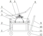
FIG. 1 is a perspective view of the present embodiment;
FIG. 2 is a schematic structural diagram of the present embodiment;
FIG. 3 is a right side structural view of the present embodiment;
FIG. 4 is a top view of the cross plate of the present embodiment;
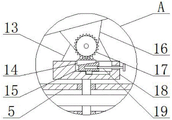
FIG. 5 is an enlarged view of the embodiment shown at A in FIG. 2;
fig. 6 is an enlarged view of the embodiment shown at B in fig. 3.
In the figure: 1. a power supply body; 2. a frame body; 3. a movable block; 4. a drive plate; 5. a transverse plate; 6. a solar panel; 7. a second threaded rod; 8. a first threaded rod; 9. a push rod; 10. a partition plate; 11. a base plate; 12. a wheel; 13. a first fixing plate; 14. a first slider; 15. a second slider; 16. a second fixing plate; 17. a first gear; 18. rotating the block; 19. a third threaded rod; 20. a second gear; 21. a movable plate.
Detailed Description
The present invention will be further described with reference to the accompanying drawings and the detailed description, and it should be noted that any combination of the embodiments or technical features described below can be used to form a new embodiment without conflict.
It will be understood that when an element is referred to as being "secured to" another element, it can be directly on the other element or intervening elements may also be present. When a component is referred to as being "connected" to another component, it can be directly connected to the other component or intervening components may also be present. When a component is referred to as being "disposed on" another component, it can be directly on the other component or intervening components may also be present. The terms "vertical," "horizontal," "left," "right," and the like as used herein are for illustrative purposes only.
Unless defined otherwise, all technical and scientific terms used herein have the same meaning as commonly understood by one of ordinary skill in the art to which this invention belongs. The terminology used in the description of the utility model herein is for the purpose of describing particular embodiments only and is not intended to be limiting of the utility model. As used herein, the term "and/or" includes any and all combinations of one or more of the associated listed items.
Referring to fig. 1 to 6, an emergency power generation portable power supply with high reliability comprises a power supply body 1, a frame body 2 is sleeved outside the power supply body 1, a bottom plate 11 is fixedly connected to the bottom of the frame body 2, a push rod 9 is fixedly connected to the top of the bottom plate 11 near the right side, vertical plates are fixedly connected to the bottom of the bottom plate 11 near the left and right sides, the two vertical plates are arranged front and back, wheels 12 are movably connected to the sides, away from each other, of the two vertical plates through a rotating shaft, the power supply body 1 is provided with a partition plate 10, the left and right sides of the partition plate 10 are respectively fixedly connected to the left and right sides of an inner cavity of the frame body 2, two movable blocks 3 are arranged at the top of the partition plate 10 near the front and back sides, the two movable blocks 3 are arranged left and right, a first threaded rod 8 is arranged between the two movable blocks 3, threaded holes are respectively arranged on the two movable blocks 3, the left and right ends of the first threaded rod 8 respectively penetrate through adjacent threaded holes and are respectively movably connected to the left and right sides of the frame body 2 through the rotating shaft, the right end of the first threaded rod 8 penetrates through the bearing and extends to the right side of the frame body 2, and is fixedly connected with a knob, a circular ring is sleeved at the middle part of the outer side of the first threaded rod 8, the first threaded rod 8 is fixedly connected with the circular ring, the rotating directions of threads on the first threaded rod 8, which are positioned at the left side and the right side of the circular ring, are opposite, so that the moving directions of the moving blocks 3 at the left side and the right side are opposite, a transverse plate 5 is arranged at the top of the frame body 2, two driving plates 4 are movably connected with the bottom of the transverse plate 5 near the front side and the back side through a connecting plate and a rotating shaft, the two driving plates 4 are arranged left and right, a groove is formed at the top of the moving block 3, the bottoms of the driving plates 4 are inserted into adjacent groove inner cavities and are movably connected with the moving blocks 3 through the rotating shaft, the transverse plate 5 is hollow, a fixing mechanism is arranged in the inner cavity of the transverse plate 5, a rotating block 18 is arranged at the top of the transverse plate, a rotating shaft is fixedly connected with the bottom of the rotating block 18, the bearing at the top and the bottom of the transverse plate 5, the bottom end of the rotating shaft sequentially penetrates through two bearings, the fixing mechanism comprises a second gear 20, the bottom end of the rotating shaft penetrates through the second gear 20, a movable plate 21 is arranged on the right side of the second gear 20, a plurality of first tooth blocks are fixedly connected to the left side of the movable plate 21 and meshed with the second gear 20, a second threaded rod 7 is movably connected to the right side of the movable plate 21 through the bearings, a threaded hole matched with the second threaded rod 7 is formed in the right side of the transverse plate 5, the right end of the second threaded rod 7 penetrates through the threaded hole and extends to the right side of the transverse plate 5, so that the angle of the solar panel 6 in the horizontal direction is adjusted, the angle is fixed through the meshing of the first tooth blocks and the second gear 20, two sliding pipes are fixedly connected to the right side of the movable plate 21 and are respectively positioned on the front side and the rear side of the second threaded rod 7, and two sliding rods matched with the sliding pipes are fixedly connected to the right side of the inner cavity of the transverse plate 5, the left end of the sliding rod is inserted in the inner cavity of the adjacent sliding pipe, the movable plate 21 is prevented from being driven to rotate when the second threaded rod 7 rotates, the solar panel 6 is arranged at the top of the rotating block 18, two first fixing plates 13 are fixedly connected to the top of the rotating block 18, the two first fixing plates 13 are arranged in the front-back direction, two second fixing plates 16 are arranged between the two first fixing plates 13, the two second fixing plates 16 are arranged in the front-back direction and are fixedly connected with the bottom of the solar panel 6, a first gear 17 is arranged between the two second fixing plates 16, a fixing shaft penetrates through the center of the first gear 17, bearings are fixedly connected to the two second fixing plates 16, the front end and the back end of the fixing shaft respectively penetrate through the adjacent bearings and are fixedly connected with the adjacent first fixing plates 13, a groove is formed in the top of the rotating block 18, a clamping mechanism is arranged in the inner cavity of the groove, and comprises a first sliding block 14 and a second sliding block 15, the first sliding block 14 and the second sliding block 15 are arranged up and down, the top of the first sliding block 14 is fixedly connected with a plurality of second tooth blocks, the second tooth blocks are meshed with the first gear 17, the right side of the rotating block 18 is provided with a third threaded rod 19, the right side of the rotating block 18 is provided with a threaded hole matched with the third threaded rod 19, the right side of the second sliding block 15 is provided with a jack, the left end of the third threaded rod 19 penetrates through the threaded hole and is inserted and connected in the inner cavity of the jack so as to adjust the vertical angle of the solar panel 6, the angle is fixed through the meshing of the second tooth blocks and the first gear 17, the jack is provided with an internal thread matched with the third threaded rod 19, so that the second sliding block 15 is driven to move when the third threaded rod 19 is rotated, the bottom of the second sliding block 15 is fixedly connected with a fixed block, the bottom of the inner cavity of the groove is provided with a sliding chute matched with the fixed block, and the moving direction of the second sliding block 15 is limited, the second slider 15 is prevented from being displaced when moved.
The working principle is as follows: when the solar energy power supply is used, the knob is rotated to drive the first threaded rod 8 to rotate, the first threaded rod 8 drives the movable blocks 3 on the left side and the right side to move towards the circular ring when rotating, so as to drive the transmission plate 4, the transverse plate 5 is supported by the transmission plate 4, the solar panel 6 is lifted, the solar panel 6 is unfolded, the solar panel 6 absorbs sunlight to charge the power supply body 1, the second threaded rod 7 is rotated, the second threaded rod 7 drives the movable plate 21 to move rightwards, so that the first tooth block is separated from the second gear 20, the fixing of the second gear 20 is released, the angle of the solar panel 6 in the horizontal direction can be adjusted, the second threaded rod 7 is reversed, the first tooth block is meshed with the second gear 20, the adjusted angle is fixed, the second sliding block 15 is driven to move rightwards by rotating the third threaded rod 19, the first sliding block 14 falls down when the second sliding block 15 moves rightwards, and drive second tooth piece and first gear 17 separation, remove the fixed to first gear 17 to can adjust the angle of solar panel 6 upper and lower direction, reverse third threaded rod 19 drives second slider 15 and moves to the left, promotes first slider 14 through second slider 15 and moves upward, and drives second tooth piece and first gear 17 meshing, thereby fixes the angle after adjusting.
The above embodiments are only preferred embodiments of the present invention, and the protection scope of the present invention is not limited thereby, and any insubstantial changes and substitutions made by those skilled in the art based on the present invention are within the protection scope of the present invention.