CN216463540U - Edge grinding machine for printed circuit board - Google Patents
Edge grinding machine for printed circuit board Download PDFInfo
- Publication number
- CN216463540U CN216463540U CN202122584146.3U CN202122584146U CN216463540U CN 216463540 U CN216463540 U CN 216463540U CN 202122584146 U CN202122584146 U CN 202122584146U CN 216463540 U CN216463540 U CN 216463540U
- Authority
- CN
- China
- Prior art keywords
- printed circuit
- circuit board
- grinding machine
- edge grinding
- machine body
- Prior art date
- Legal status (The legal status is an assumption and is not a legal conclusion. Google has not performed a legal analysis and makes no representation as to the accuracy of the status listed.)
- Expired - Fee Related
Links
- 230000000670 limiting effect Effects 0.000 claims abstract description 27
- 238000007688 edging Methods 0.000 claims description 24
- 238000009434 installation Methods 0.000 claims description 10
- 238000000034 method Methods 0.000 abstract description 9
- 238000005498 polishing Methods 0.000 abstract description 7
- 238000004519 manufacturing process Methods 0.000 abstract description 4
- 230000008569 process Effects 0.000 abstract description 3
- 230000008859 change Effects 0.000 description 2
- 230000004048 modification Effects 0.000 description 2
- 238000012986 modification Methods 0.000 description 2
- 230000000903 blocking effect Effects 0.000 description 1
- 230000007547 defect Effects 0.000 description 1
- 238000010586 diagram Methods 0.000 description 1
- 230000001788 irregular Effects 0.000 description 1
- 230000007246 mechanism Effects 0.000 description 1
- 230000008092 positive effect Effects 0.000 description 1
Images


Landscapes
- Grinding Of Cylindrical And Plane Surfaces (AREA)
Abstract
The utility model relates to the technical field of edge grinding machines for printed circuit boards, in particular to an edge grinding machine for a printed circuit board. The edge grinding machine comprises an edge grinding machine body and a limiting structure, wherein steering equipment is mounted on the surface of the edge grinding machine body, the limiting structure is arranged on the surface of the edge grinding machine body and comprises a fixed plate, the surface of the fixed plate is fixedly connected with the edge grinding machine body, a first screw rod is in threaded connection with the surface of the fixed plate, a movable plate is rotatably connected to one end of the first screw rod, two connecting rods are inserted into the surface of the movable plate in a sliding mode, first springs are sleeved on arc surfaces of the two connecting rods, one end of each first spring is fixedly connected with the movable plate, and a baffle is fixedly connected to the other end of each first spring. The utility model solves the problems that the edge of the printed circuit board is easy to slide in the process of polishing the edge of the printed circuit board, and the edge of the printed circuit board is not uniformly polished, so that the production quality of the printed circuit board is reduced.
Description
Technical Field
The utility model relates to the technical field of edge grinding machines for printed circuit boards, in particular to an edge grinding machine for a printed circuit board.
Background
The edge grinding machine for the printed circuit board is equipment for grinding burrs at the edge of the printed circuit board, and the traditional grinding machine for the printed circuit board has the advantages that the limiting effect of the grinding machine for the printed circuit board is poor, so that the edge of the printed circuit board is easy to slide in the process of grinding the edge of the printed circuit board, the edge of the printed circuit board is not uniformly ground, and the production quality of the printed circuit board is reduced.
SUMMERY OF THE UTILITY MODEL
The utility model aims to solve the defects that in the prior art, the edge of a printed circuit board is easy to slide in the process of polishing the edge of the printed circuit board, and the edge of the printed circuit board is not uniformly polished, so that the production quality of the printed circuit board is reduced.
In order to achieve the purpose, the utility model adopts the following technical scheme: the utility model provides a printed circuit board edging machine, includes edging machine body and limit structure, the surface mounting of edging machine body has the equipment that turns to, the surface of edging machine body is equipped with limit structure, limit structure includes the fixed plate, the surface and edging machine body fixed connection of fixed plate, the surperficial threaded connection of fixed plate has first screw rod, the one end of first screw rod is rotated and is connected with the fly leaf, the surface slip of fly leaf is inserted and is equipped with two connecting rods, two the arc surface of connecting rod all overlaps there is first spring, the one end and the fly leaf fixed connection of first spring, the other end fixedly connected with baffle of first spring, the surface and the connecting rod fixed connection of baffle can support printed circuit board through above-mentioned part, prevent that printed circuit board from removing the in-process skew of edging.
Preferably, the arc surface sliding connection of connecting rod has the limiting plate, the surface and the edging machine body fixed connection of limiting plate can prevent fly leaf and baffle rotation through the connecting rod and the limiting plate of extension.
Preferably, the surface of the baffle is fixedly connected with an inclined plate, and the inclined plate is rectangular in shape, so that the printed circuit board is prevented from being clamped at the edge of the baffle.
Preferably, a plurality of trompil has been seted up on the surface of baffle, and the inner wall of a plurality of trompil all rotates and is connected with a plurality of first pulley, can reduce the frictional force of printed circuit board and baffle.
Preferably, the surface of edging machine body is equipped with four auxiliary structure, auxiliary structure includes the mounting panel, the surface and edging machine body fixed connection of mounting panel, the surperficial threaded connection of mounting panel has the second screw rod, the one end of second screw rod is rotated and is connected with the installation pipe, the inner wall sliding connection of mounting panel has the slide bar, the arc surface of slide bar rotates and is connected with two second pulleys, the shape of slide bar is "T" font, can push down printed circuit board.
Preferably, the arc surface of the installation pipe is fixedly connected with a limiting rod, and the arc surface of the limiting rod is connected with the installation plate in a sliding mode to prevent the installation pipe from rotating.
Preferably, the surface of the mounting tube is fixedly connected with a second spring, and one end of the second spring is fixedly connected with the sliding rod, so that the second pulley can better press the printed circuit board.
Compared with the prior art, the utility model has the advantages and positive effects that:
in the utility model, by arranging the limit structure, when the edge of the printed circuit board needs to be polished, the first screw rod is firstly rotated to drive the movable plate to move, the movable plate drives the baffle plate to move together by pushing the first spring, the first spring can adapt to the width of the printed circuit board, when the width of the printed circuit board is different due to burrs of the printed circuit board, the first spring can be compressed to facilitate the printed circuit to smoothly slide on the baffle plate, when the width is adjusted to be proper, the edge polisher body and the steering equipment are started, when the printed circuit passes through the steering equipment, the printed circuit board rotates when the steering equipment rotates, one side of the printed circuit board is close to one side of the polishing device of the edge polisher body and then enters one side of the baffle plate of the limit structure, the polishing of the printed circuit board is smoothly carried out, and the connecting rod and the limit plate can prevent the baffle plate from rotating, make the device more stable, first pulley can reduce frictional force, through using limit structure, at the in-process that printed circuit board polished, can restrict printed circuit board through adjusting the baffle, effectively avoid the in-process printed circuit board skew of polishing, promoted the quality of printed circuit board production.
Drawings
Fig. 1 is a schematic perspective view of an edge grinding machine for a printed circuit board according to the present invention;
fig. 2 is a schematic structural view of a limiting structure of an edge grinding machine for a printed circuit board according to the present invention;
fig. 3 is a schematic view of a part of the structure of the limiting structure of the edge grinding machine for a printed circuit board according to the present invention;
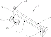
fig. 4 is a schematic structural diagram of an auxiliary structure of an edge grinding machine for a printed circuit board according to the present invention.
Illustration of the drawings: 1. an edge grinding machine body; 2. a steering device; 3. a limiting structure; 31. a fixing plate; 32. a first screw; 33. a movable plate; 34. a connecting rod; 35. a baffle plate; 36. a first spring; 37. a limiting plate; 38. a first pulley; 4. an auxiliary structure; 41. mounting a plate; 42. a second screw; 43. installing a pipe; 44. a slide bar; 45. a second pulley; 46. a second spring; 47. a limiting rod.
Detailed Description
In order that the above objects, features and advantages of the present invention can be more clearly understood, the present invention will be further described with reference to the accompanying drawings and examples. It should be noted that the embodiments and features of the embodiments of the present application may be combined with each other without conflict.
In the following description, numerous specific details are set forth in order to provide a thorough understanding of the present invention, however, the present invention may be practiced in other ways than those specifically described herein, and thus the present invention is not limited to the specific embodiments of the present disclosure.
Referring to fig. 1-4, the present invention provides a technical solution: the utility model provides a printed circuit board edging machine, includes edging machine body 1 and limit structure 3, and the surface mounting of edging machine body 1 has and turns to equipment 2, and the surface of edging machine body 1 is equipped with limit structure 3, and the surface of edging machine body 1 is equipped with four auxiliary structure 4.
The specific arrangement and function of the limit structure 3 and the auxiliary structure 4 will be described in detail below.
In this embodiment: limiting structure 3 includes fixed plate 31, the surface and the edging machine body 1 fixed connection of fixed plate 31, the surperficial threaded connection of fixed plate 31 has first screw rod 32, the one end of first screw rod 32 is rotated and is connected with fly leaf 33, fly leaf 33's surperficial slip is inserted and is equipped with two connecting rods 34, the arc surface of two connecting rods 34 all overlaps there is first spring 36, the one end and the fly leaf 33 fixed connection of first spring 36, the other end fixedly connected with baffle 35 of first spring 36, the surface and the connecting rod 34 fixed connection of baffle 35, can support printed circuit board through above-mentioned part, prevent that printed circuit board from removing the in-process skew of edging, first spring 36 can self-adaptation printed circuit board's width, prevent that printed circuit board from blocking.
Specifically, the arc surface of connecting rod 34 has limiting plate 37, and limiting plate 37's surface and edging machine body 1 fixed connection can prevent that fly leaf 33 and baffle 35 from rotating, hoisting device's stability through the connecting rod 34 and the limiting plate 37 of extension.
Specifically, the surface of the baffle 35 is fixedly connected with an inclined plate, and the inclined plate is rectangular.
In this embodiment: the printed circuit board is convenient to slide into one side of the baffle 35 through the inclined plate with a certain angle, so that the printed circuit board is prevented from being clamped at the edge of the baffle 35.
Specifically, a plurality of trompil has been seted up on the surface of baffle 35, and the inner wall of a plurality of trompil all rotates and is connected with a plurality of first pulley 38.
In this embodiment: the friction force between the printed circuit board and the baffle 35 can be reduced, and the printed circuit board can slide conveniently.
Specifically, auxiliary structure 4 includes mounting panel 41, mounting panel 41's surface and edging machine body 1 fixed connection, and mounting panel 41's surperficial threaded connection has second screw rod 42, and the one end of second screw rod 42 is rotated and is connected with installation pipe 43, and mounting panel 41's inner wall sliding connection has slide bar 44, and slide bar 44's arc surface rotates and is connected with two second pulleys 45.
In this embodiment: the printed circuit board can be pressed, the printed circuit board is prevented from tilting, and the edge treatment of the printed circuit board is irregular.
Specifically, the arc surface of the mounting tube 43 is fixedly connected with a limiting rod 47, and the arc surface of the limiting rod 47 is slidably connected with the mounting plate 41, so that the mounting tube 43 is prevented from rotating, and the sliding rod 44 is stably and vertically placed.
Specifically, a second spring 46 is fixedly connected to the surface of the mounting tube 43, and one end of the second spring 46 is fixedly connected to the sliding rod 44.
In this embodiment: the second pulley 45 can be made to press the printed circuit board better, further preventing the printed circuit board from tilting.
The working principle is as follows: by arranging the limiting structure 3, when the edge of the printed circuit board needs to be polished, the first screw rod 32 is firstly rotated, the first screw rod 32 drives the movable plate 33 to move, the movable plate 33 drives the baffle 35 to move together by pushing the first spring 36, the first spring 36 can adapt to the width of the printed circuit board, when the burr of the printed circuit board causes the width difference of the printed circuit board, the first spring 36 can be compressed to facilitate the printed circuit to slide smoothly on the baffle 35, when the proper width is adjusted, the edge grinding machine body 1 and the steering equipment 2 are started, when the printed circuit passes through the steering equipment 2, the printed circuit board rotates when the steering mechanism of the steering equipment 2, one side of the printed circuit board is close to one side of the polishing device of the edge grinding machine body 1 and then enters one side of the baffle 35 of the limiting structure 3, and the polishing of the printed circuit board is smoothly performed at the moment, connecting rod 34 and limiting plate 37 can prevent that baffle 35 from rotating, make the device more stable, first pulley 38 can reduce frictional force, in order to prevent printed circuit board at the in-process perk of removal, through setting up auxiliary structure 4, before printed circuit board polishes, adjust when limiting structure 3 and accomplish the back, at first rotate second screw rod 42, make second screw rod 42 drive installation pipe 43 to the direction removal that is close to baffle 35 until installation pipe 43 is close to baffle 35, and keep suitable distance, at the in-process that printed circuit board moved on edging machine body 1, second pulley 45 with prevent the printed circuit board perk, second spring 46 can further make second pulley 45 push down printed circuit board, gag lever post 47 can prevent that installation pipe 43 from rotating.
The above description is only a preferred embodiment of the present invention, and not intended to limit the present invention in other forms, and any person skilled in the art may apply the above modifications or changes to the equivalent embodiments with equivalent changes, without departing from the technical spirit of the present invention, and any simple modification, equivalent change and change made to the above embodiments according to the technical spirit of the present invention still belong to the protection scope of the technical spirit of the present invention.
Claims (7)
1. The utility model provides a printed circuit board edging machine, includes edging machine body (1) and limit structure (3), its characterized in that: the surface of the edge grinding machine body (1) is provided with a steering device (2), the surface of the edge grinding machine body (1) is provided with a limiting structure (3), the limiting structure (3) comprises a fixing plate (31), the surface of the fixing plate (31) is fixedly connected with the edge grinding machine body (1), the surface of the fixed plate (31) is in threaded connection with a first screw (32), one end of the first screw (32) is rotatably connected with a movable plate (33), two connecting rods (34) are inserted on the surface of the movable plate (33) in a sliding way, first springs (36) are sleeved on the arc surfaces of the two connecting rods (34), one end of the first spring (36) is fixedly connected with the movable plate (33), the other end of the first spring (36) is fixedly connected with a baffle plate (35), and the surface of the baffle plate (35) is fixedly connected with the connecting rod (34).
2. The edge grinding machine for printed circuit boards according to claim 1, characterized in that: the arc surface of connecting rod (34) sliding connection has limiting plate (37), the surperficial and edging machine body (1) fixed connection of limiting plate (37).
3. The edge grinding machine for printed circuit boards according to claim 1, characterized in that: the surface of the baffle (35) is fixedly connected with an inclined plate, and the inclined plate is rectangular.
4. The edge grinding machine for printed circuit boards according to claim 1, characterized in that: a plurality of trompil has been seted up on the surface of baffle (35), and the inner wall of a plurality of trompil all rotates and is connected with a plurality of first pulley (38).
5. The edge grinding machine for printed circuit boards according to claim 1, characterized in that: the surface of edging machine body (1) is equipped with four auxiliary structure (4), auxiliary structure (4) include mounting panel (41), the surface and edging machine body (1) fixed connection of mounting panel (41), the surperficial threaded connection of mounting panel (41) has second screw rod (42), the one end of second screw rod (42) is rotated and is connected with installation pipe (43), the inner wall sliding connection of mounting panel (41) has slide bar (44), the arc surface of slide bar (44) is rotated and is connected with two second pulleys (45).
6. The edge grinding machine for printed circuit boards according to claim 5, wherein: the arc surface of installation pipe (43) fixedly connected with gag lever post (47), the arc surface and mounting panel (41) sliding connection of gag lever post (47).
7. The edge grinding machine for printed circuit boards according to claim 5, wherein: the surface of the mounting tube (43) is fixedly connected with a second spring (46), and one end of the second spring (46) is fixedly connected with the sliding rod (44).
Priority Applications (1)
| Application Number | Priority Date | Filing Date | Title |
|---|---|---|---|
| CN202122584146.3U CN216463540U (en) | 2021-10-26 | 2021-10-26 | Edge grinding machine for printed circuit board |
Applications Claiming Priority (1)
| Application Number | Priority Date | Filing Date | Title |
|---|---|---|---|
| CN202122584146.3U CN216463540U (en) | 2021-10-26 | 2021-10-26 | Edge grinding machine for printed circuit board |
Publications (1)
| Publication Number | Publication Date |
|---|---|
| CN216463540U true CN216463540U (en) | 2022-05-10 |
Family
ID=81442400
Family Applications (1)
| Application Number | Title | Priority Date | Filing Date |
|---|---|---|---|
| CN202122584146.3U Expired - Fee Related CN216463540U (en) | 2021-10-26 | 2021-10-26 | Edge grinding machine for printed circuit board |
Country Status (1)
| Country | Link |
|---|---|
| CN (1) | CN216463540U (en) |
-
2021
- 2021-10-26 CN CN202122584146.3U patent/CN216463540U/en not_active Expired - Fee Related
Similar Documents
| Publication | Publication Date | Title |
|---|---|---|
| CN108972172A (en) | A kind of rotary tube grinding device | |
| CN207578131U (en) | A kind of bending handware side wall polishing mechanism | |
| CN216657321U (en) | A Cylindrical Grinder With Easy Wheel Replacement | |
| CN211916531U (en) | Polishing tool | |
| CN112388471A (en) | A burnishing and polishing equipment for circular plank surface | |
| CN220740559U (en) | Multi-angle grinding device | |
| CN216577292U (en) | Conveying structure of surface grinding machine | |
| CN219004755U (en) | Cutting equipment is used in three-way pipe processing | |
| CN215588747U (en) | Grinding device is used in processing of cell-phone glass board | |
| CN215317629U (en) | Edging device for ceramic tile blank production and processing | |
| CN220463193U (en) | A kind of sharpening lathe for processing cutting tools | |
| CN116572090A (en) | Knife sharpening device for blade processing | |
| CN209887257U (en) | Grinding equipment for machining crane parts | |
| CN211639349U (en) | Self-adjusting automatic polishing machine | |
| CN216399220U (en) | A grinding and polishing table | |
| CN218427317U (en) | Polishing ring fixing piece for surface grinding machine | |
| CN221936365U (en) | A kind of decoration wood surface polishing device | |
| CN211940249U (en) | Wire drawing mechanism capable of adjusting wire drawing position | |
| CN220718967U (en) | Sharpening mechanism for pencil | |
| CN221248067U (en) | Edging device convenient to dismouting | |
| CN220741499U (en) | Log positioning and processing device | |
| CN221517148U (en) | Seal cutting stone seal grinding device | |
| CN216706074U (en) | Log door component vertical milling forming device | |
| CN222269904U (en) | Grinding machine with adjustable clamp | |
| CN223630100U (en) | A steering and fixing device for a polishing machine |
Legal Events
| Date | Code | Title | Description |
|---|---|---|---|
| GR01 | Patent grant | ||
| GR01 | Patent grant | ||
| CF01 | Termination of patent right due to non-payment of annual fee |
Granted publication date: 20220510 |
|
| CF01 | Termination of patent right due to non-payment of annual fee |