CN216460986U - Novel hydraulic plate bending machine - Google Patents
Novel hydraulic plate bending machine Download PDFInfo
- Publication number
- CN216460986U CN216460986U CN202122801003.3U CN202122801003U CN216460986U CN 216460986 U CN216460986 U CN 216460986U CN 202122801003 U CN202122801003 U CN 202122801003U CN 216460986 U CN216460986 U CN 216460986U
- Authority
- CN
- China
- Prior art keywords
- wall
- fixedly connected
- plate
- workbench
- material guiding
- Prior art date
- Legal status (The legal status is an assumption and is not a legal conclusion. Google has not performed a legal analysis and makes no representation as to the accuracy of the status listed.)
- Expired - Fee Related
Links
- 238000005452 bending Methods 0.000 title claims abstract description 39
- 239000000463 material Substances 0.000 claims abstract description 71
- 230000007246 mechanism Effects 0.000 claims abstract description 34
- 238000010438 heat treatment Methods 0.000 claims description 17
- 239000002184 metal Substances 0.000 claims description 9
- 230000001681 protective effect Effects 0.000 claims description 8
- 230000002457 bidirectional effect Effects 0.000 abstract description 4
- 238000010586 diagram Methods 0.000 description 2
- 238000007599 discharging Methods 0.000 description 2
- 230000001174 ascending effect Effects 0.000 description 1
- 230000009286 beneficial effect Effects 0.000 description 1
- 230000007423 decrease Effects 0.000 description 1
- 230000007547 defect Effects 0.000 description 1
- 238000005516 engineering process Methods 0.000 description 1
- 208000037805 labour Diseases 0.000 description 1
- 238000000034 method Methods 0.000 description 1
- 238000012986 modification Methods 0.000 description 1
- 230000004048 modification Effects 0.000 description 1
Images


Landscapes
- Bending Of Plates, Rods, And Pipes (AREA)
Abstract
The utility model discloses a novel hydraulic plate bending machine which comprises a workbench, wherein one end of the workbench is provided with an electric control mechanism, two ends of the outer wall of the top of the workbench are fixedly connected with supporting rods, the outer wall of the top of each supporting rod is fixedly connected with a top plate, two ends of the outer wall of the bottom of each top plate are respectively provided with a sliding groove, and two ends of the inner wall of each sliding groove are respectively connected with a sliding block in a sliding manner. According to the utility model, the rotary bidirectional threaded screw rod is arranged, so that the sliding blocks on the outer wall of the bidirectional threaded screw rod are controlled to separate and move in opposite directions in the sliding groove, and the distance between the material guide mechanisms at the bottom of the third telescopic rod at the bottom of the sliding block is controlled, so that the material guide distance can be adjusted according to the length of a sheet material, the bending efficiency is improved, the lifting upper die is arranged, the third telescopic rod is driven to lift by the first telescopic rod, the third telescopic rod is driven to lift, the purposes of driving the sheet material in the material guide mechanisms to descend, bend, ascend and discharge are finally realized, and the bending efficiency is further improved.
Description
Technical Field
The utility model relates to the technical field of bending machines, in particular to a novel hydraulic plate bending machine.
Background
The bending machine is a machine capable of bending thin plates, and mainly structurally comprises a support, a workbench and a clamping plate, wherein the workbench is arranged on the support and comprises a base and a pressing plate, the base is connected with the clamping plate through a hinge and comprises a seat shell, a coil and a cover plate, the coil is arranged in a recess of the seat shell, and the cover plate covers the top of the recess. When the clamping device is used, the coil is electrified by the conducting wire, and the attraction is generated on the pressing plate after the coil is electrified, so that the thin plate between the pressing plate and the base is clamped. The electromagnetic clamping is adopted, so that the pressing plate can be made into various workpiece requirements, the workpiece with the side wall can be machined, and the operation is very simple and convenient.
Traditional bender needs a large amount of labours to wait to bend panel propulsion bender inside back when the feeding, can't adjust the guide mechanism of inside according to the sheet material of different length, is unfavorable for the efficiency of bending to current bender is complicated to bending and the operation when the ejection of compact of sheet material when bending, and is not smooth enough, is unfavorable for the efficiency of bending, consequently studies a high efficiency bender convenient to adjust and seems necessary.
SUMMERY OF THE UTILITY MODEL
The utility model aims to solve the defects in the prior art and provides a novel hydraulic plate bending machine.
In order to achieve the purpose, the utility model adopts the following technical scheme:
a novel hydraulic plate bending machine comprises a workbench, wherein one end of the workbench is provided with an electric control mechanism, two ends of the outer wall of the top of the workbench are fixedly connected with supporting rods, the outer wall of the top of the supporting rods is fixedly connected with a top plate, two ends of the outer wall of the bottom of the top plate are provided with sliding grooves, two ends of the inner wall of the sliding grooves are respectively and slidably connected with a sliding block, the inner wall of the sliding block is in threaded connection with a two-way threaded lead screw, the two-way threaded lead screw is in rotating connection with the top plate, the top of the top plate is fixedly connected with a hydraulic mechanism, the bottom of the hydraulic mechanism is fixedly connected with a connecting rod, the bottom of the connecting rod is fixedly connected with an upper die, the bottom of the sliding block is fixedly connected with a third telescopic rod, the bottom of the third telescopic rod is provided with a material guide mechanism, one end of the third telescopic rod is fixedly connected with a first telescopic rod, and the other end of the first telescopic rod is fixedly connected with the upper die, and a lower die is arranged at the bottom of the upper die.
Preferably, the bottom of the lower die is fixedly connected with a bottom plate, the two ends of the outer wall of the top of the bottom plate are in threaded connection with bolts, the bolts are in threaded connection with a workbench, and the bottom plate and the workbench are detachably connected through the bolts.
Preferably, the material guiding mechanism comprises a first material guiding frame and a second material guiding frame, the first material guiding frame is provided with a material guiding groove, the top and the bottom of the inner wall of the material guiding groove are respectively and rotatably connected with a first material guiding roller, the outer walls of two sides of the second material guiding frame are respectively and fixedly connected with a second telescopic rod, and the top and the bottom of the inner wall of the second material guiding frame are respectively and rotatably connected with a second material guiding roller.
Preferably, slots are formed in two ends of the outer wall of the top of the workbench and located at the bottoms of the first guide frame and the second guide frame.
Preferably, a bolt is arranged at one end, close to the second material guide frame, of the workbench, and a jack is formed in the outer wall of the second material guide frame.
Preferably, the bottom of the upper die is fixedly connected with a protective backing plate.
Preferably, go up mould inner wall fixedly connected with hot plate, a plurality of heat conduction metal poles of hot plate bottom fixedly connected with, heat conduction metal pole bottom and protection backing plate fixed connection, a plurality of heating pipes of bed die inner wall fixedly connected with, heating pipe and hot plate respectively with electrical control mechanism electric connection.
The utility model has the beneficial effects that:
1. rotate two-way screw lead screw through setting up, thereby the slider of control two-way screw lead screw outer wall leaves mutually and moves in opposite directions at the spout, thereby distance between the third telescopic link bottom guide mechanism of control slider bottom, thereby can adjust the guide distance according to sheet material length, the efficiency of bending has been improved, last mould through setting up the lift utilizes first telescopic link to drive the third telescopic link lift, thereby drive the third telescopic link lift, finally realized driving the sheet material decline in the guide mechanism and bent and the purpose of the ejection of compact that rises, further improve the efficiency of bending.
2. Through setting up and being connected by the second telescopic link between the second guide frame, in second guide frame descends to the slot, through setting up in the bolt inserts the jack of second guide frame outer wall to make the vertical height of second guide frame uprise, thereby the sheet material after being convenient for bend is carried out from second guide frame, improves ejection of compact convenience.
3. The heating plate in the upper die is controlled by the electric control mechanism to heat the protective base plate by utilizing the heat conducting metal rod, so that the top of the plate is heated, the bending efficiency of the plate is improved, and the heating pipe in the lower die is controlled by the electric control mechanism to heat the bottom of the plate, so that the bending efficiency of the plate is further improved.
Drawings
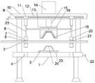
Fig. 1 is a schematic sectional structure diagram of a novel hydraulic plate bending machine according to embodiment 1 of the present invention;
fig. 2 is a schematic structural diagram of a main body of a material guiding mechanism of the novel hydraulic plate bending machine provided by the utility model;
fig. 3 is a schematic partial sectional structure view of a novel hydraulic plate bending machine according to embodiment 2 of the present invention.
In the figure: 1 workstation, 2 heating pipes, 3 bolts, 4 slots, 5 first guide material rollers, 6 baffle boxes, 7 first guide material racks, 8 bracing pieces, 9 two-way screw lead screws, 10 roof, 11 sliders, 12 chutes, 13 first telescopic links, 14 hydraulic pressure mechanism, 15 connecting rods, 16 upper dies, 17 hot plates, 18 heat conduction metal poles, 19 protective backing plates, 20 second guide material racks, 21 second telescopic links, 22 bolts, 23 bottom plates, 24 lower dies, 25 third telescopic links, 26 second guide material rollers, 27 jacks.
Detailed Description
The technical solutions in the embodiments of the present invention will be clearly and completely described below with reference to the drawings in the embodiments of the present invention, and it is obvious that the described embodiments are only a part of the embodiments of the present invention, and not all of the embodiments.
Example 1
Referring to fig. 1-2, a novel hydraulic plate bending machine comprises a workbench 1, wherein an electric control mechanism is arranged at one end of the workbench 1, support rods 8 are fixedly connected to both ends of the outer wall of the top of the workbench 1, a top plate 10 is fixedly connected to the outer wall of the top of each support rod 8, slide grooves 12 are respectively formed at both ends of the outer wall of the bottom of each top plate 10, slide blocks 11 are respectively and slidably connected to both ends of the inner wall of each slide groove 12, a bidirectional threaded lead screw 9 is in threaded connection with the inner wall of each slide block 11, the bidirectional threaded lead screw 9 is rotatably connected with the top plate 10, a hydraulic mechanism 14 is fixedly connected to the top of each top plate 10, a connecting rod 15 is fixedly connected to the bottom of each hydraulic mechanism 14, an upper die 16 is fixedly connected to the bottom of each connecting rod 15, a third telescopic rod 25 is fixedly connected to the bottom of each slide block 11, a material guiding mechanism is arranged at the bottom of each third telescopic rod 25, a first telescopic rod 13 is fixedly connected to one end of each third telescopic rod 25, and the other end of each first telescopic rod 13 is fixedly connected with the upper die 16, the bottom of the upper die 16 is provided with a lower die 24, the two-way threaded screw rod 9 is rotated through setting, so that the sliding block 11 for controlling the outer wall of the two-way threaded screw rod 9 is separated from and moves towards each other in the sliding groove 12, the distance between the material guide mechanisms at the bottom of the third telescopic rod 25 at the bottom of the sliding block 11 is controlled, the material guide distance can be adjusted according to the length of a plate material, the bending efficiency is improved, the lifting upper die 16 is arranged to drive the third telescopic rod 25 to lift through the first telescopic rod 13, the third telescopic rod 25 is driven to lift, the purposes of descending, bending and ascending and discharging of the plate material in the material guide mechanism are finally achieved, and the bending efficiency is further improved.
According to the utility model, the bottom of the lower die 24 is fixedly connected with the bottom plate 23, both ends of the outer wall of the top of the bottom plate 23 are in threaded connection with the bolts 3, the bolts 3 are in threaded connection with the workbench 1, and the bottom plate 23 and the workbench 1 are detachably connected through the bolts 3, so that the lower die 24 can be conveniently detached and replaced;
the material guiding mechanism comprises a first material guiding frame 7 and a second material guiding frame 20, wherein the first material guiding frame 7 is provided with a material guiding groove 6, the top and the bottom of the inner wall of the material guiding groove 6 are both rotatably connected with a first material guiding roller 5, the outer walls of two sides of the second material guiding frame 20 are both fixedly connected with second telescopic rods 21, the top and the bottom of the inner wall of the second material guiding frame 20 are both rotatably connected with second material guiding rollers 26, two ends of the outer wall of the top of the workbench 1 are both provided with slots 4, the slots 4 are positioned at the bottoms of the first material guiding frame 7 and the second material guiding frame 20, one end of the workbench 1, which is close to the second material guiding frame 20, is provided with a bolt 22, the outer wall of the second material guiding frame 20 is provided with a jack 27, the second material guiding frame 20 is connected by the second telescopic rods 21, when the second material guiding frame 20 descends into the slots 4, the bolt 22 is inserted into the jack 27 on the outer wall of the second material guiding frame 20, so that the longitudinal height of the second material guiding frame 20 is increased, therefore, the bent plate can be conveniently conveyed out of the second material guide frame 20, and the discharging convenience is improved;
the bottom of the upper die 16 is fixedly connected with a protective backing plate 19 for protecting the bottom of the upper die 16.
The working principle is as follows: at the idle position of the device, all the components are referred to as structural members to be connected, the components are connected in sequence, the detailed connection means is the known technology in the field, the following main description of the working principle and the process is omitted, when the device is used, the two-way threaded screw rod 9 is arranged and rotated, so that the sliding block 11 on the outer wall of the two-way threaded screw rod 9 is controlled to move away from and towards the sliding groove 12, the distance between the material guide mechanisms at the bottom of the third telescopic rod 25 at the bottom of the sliding block 11 is controlled, the material guide distance can be adjusted according to the length of the sheet material, the bending efficiency is improved, the lifting upper die 16 is arranged to drive the third telescopic rod 25 to lift by using the first telescopic rod 13, so as to drive the third telescopic rod 25 to lift, and finally realize the purposes of driving the sheet material in the material guide mechanism to descend, bend, ascend and discharge, further improve the efficiency of bending.
Example 2
Referring to fig. 2-3, a novel hydraulic plate bending machine, an upper die 16 is fixedly connected with a heating plate 17 on the inner wall, a plurality of heat conducting metal rods 18 are fixedly connected with the bottom of the heating plate 17, the bottom of the heat conducting metal rods 18 is fixedly connected with a protective backing plate 19, a plurality of heating pipes 2 are fixedly connected with the inner wall of a lower die 24, and the heating pipes 2 and the heating plate 17 are respectively electrically connected with an electric control mechanism.
The working principle is as follows: the heating plate 17 in the upper die 16 is controlled by the electric control mechanism to heat the protective base plate 19 by the heat conducting metal rod 18, so that the top of the plate is heated, the bending efficiency of the plate is improved, and the heating pipe 2 in the lower die 24 is controlled by the electric control mechanism to heat the bottom of the plate, so that the bending efficiency of the plate is further improved.
The above description is only for the preferred embodiment of the present invention, but the scope of the present invention is not limited thereto, and any person skilled in the art should be considered to be within the technical scope of the present invention, and equivalent alternatives or modifications according to the technical solution of the present invention and the inventive concept thereof should be covered by the scope of the present invention.
Claims (7)
1. A novel hydraulic plate bending machine comprises a workbench (1), wherein one end of the workbench (1) is provided with an electric control mechanism, and the novel hydraulic plate bending machine is characterized in that two ends of the outer wall of the top of the workbench (1) are fixedly connected with supporting rods (8), the outer wall of the top of the supporting rods (8) is fixedly connected with a top plate (10), two ends of the outer wall of the bottom of the top plate (10) are respectively provided with a sliding chute (12), two ends of the inner wall of the sliding chute (12) are respectively and slidably connected with a sliding block (11), the inner wall of the sliding block (11) is in threaded connection with a two-way threaded lead screw (9), the two-way threaded lead screw (9) is rotatably connected with the top plate (10), the top of the top plate (10) is fixedly connected with a hydraulic mechanism (14), the bottom of the hydraulic mechanism (14) is fixedly connected with a connecting rod (15), the bottom of the connecting rod (15) is fixedly connected with an upper die (16), and the bottom of the sliding block (11) is fixedly connected with a third telescopic rod (25), the material guide mechanism is arranged at the bottom of the third telescopic rod (25), one end of the third telescopic rod (25) is fixedly connected with a first telescopic rod (13), the other end of the first telescopic rod (13) is fixedly connected with an upper die (16), and a lower die (24) is arranged at the bottom of the upper die (16).
2. A novel hydraulic plate bending machine according to claim 1, wherein a bottom plate (23) is fixedly connected to the bottom of the lower die (24), bolts (3) are connected to both ends of the outer wall of the top of the bottom plate (23) in a threaded manner, the bolts (3) are connected with the workbench (1) in a threaded manner, and the bottom plate (23) is detachably connected with the workbench (1) through the bolts (3).
3. The novel hydraulic plate bending machine according to claim 1, wherein the material guiding mechanism comprises a first material guiding frame (7) and a second material guiding frame (20), a material guiding groove (6) is formed in the first material guiding frame (7), the top and the bottom of the inner wall of the material guiding groove (6) are rotatably connected with a first material guiding roller (5), the outer walls of two sides of the second material guiding frame (20) are fixedly connected with second telescopic rods (21), and the top and the bottom of the inner wall of the second material guiding frame (20) are rotatably connected with a second material guiding roller (26).
4. A novel hydraulic plate bending machine according to claim 1, characterized in that slots (4) are formed in both ends of the outer wall of the top of the workbench (1), and the slots (4) are located at the bottoms of the first material guide frame (7) and the second material guide frame (20).
5. A novel hydraulic plate bending machine according to claim 1, characterized in that a plug (22) is arranged at one end of the workbench (1) close to the second guide frame (20), and a jack (27) is arranged on the outer wall of the second guide frame (20).
6. A novel hydraulic plate bending machine according to claim 1, characterized in that a protective backing plate (19) is fixedly connected to the bottom of said upper die (16).
7. The novel hydraulic plate bending machine according to claim 1, characterized in that a heating plate (17) is fixedly connected to the inner wall of the upper die (16), a plurality of heat-conducting metal rods (18) are fixedly connected to the bottom of the heating plate (17), the bottom of each heat-conducting metal rod (18) is fixedly connected to a protective backing plate (19), a plurality of heating pipes (2) are fixedly connected to the inner wall of the lower die (24), and the heating pipes (2) and the heating plate (17) are electrically connected to an electric control mechanism respectively.
Priority Applications (1)
| Application Number | Priority Date | Filing Date | Title |
|---|---|---|---|
| CN202122801003.3U CN216460986U (en) | 2021-11-16 | 2021-11-16 | Novel hydraulic plate bending machine |
Applications Claiming Priority (1)
| Application Number | Priority Date | Filing Date | Title |
|---|---|---|---|
| CN202122801003.3U CN216460986U (en) | 2021-11-16 | 2021-11-16 | Novel hydraulic plate bending machine |
Publications (1)
| Publication Number | Publication Date |
|---|---|
| CN216460986U true CN216460986U (en) | 2022-05-10 |
Family
ID=81396954
Family Applications (1)
| Application Number | Title | Priority Date | Filing Date |
|---|---|---|---|
| CN202122801003.3U Expired - Fee Related CN216460986U (en) | 2021-11-16 | 2021-11-16 | Novel hydraulic plate bending machine |
Country Status (1)
| Country | Link |
|---|---|
| CN (1) | CN216460986U (en) |
Cited By (3)
| Publication number | Priority date | Publication date | Assignee | Title |
|---|---|---|---|---|
| CN114769374A (en) * | 2022-06-16 | 2022-07-22 | 江苏中岦绿建建材科技有限公司 | A press-bending device for manufacturing a prefab house |
| CN115121662A (en) * | 2022-09-01 | 2022-09-30 | 泰州市巨久不锈钢有限公司 | Stainless steel plate bending equipment |
| CN115488198A (en) * | 2022-11-21 | 2022-12-20 | 吉林省新诺达交通设备有限公司 | Stainless steel spout forming die that bends |
-
2021
- 2021-11-16 CN CN202122801003.3U patent/CN216460986U/en not_active Expired - Fee Related
Cited By (5)
| Publication number | Priority date | Publication date | Assignee | Title |
|---|---|---|---|---|
| CN114769374A (en) * | 2022-06-16 | 2022-07-22 | 江苏中岦绿建建材科技有限公司 | A press-bending device for manufacturing a prefab house |
| CN114769374B (en) * | 2022-06-16 | 2022-09-09 | 江苏中岦绿建建材科技有限公司 | A press-bending device for manufacturing a prefab house |
| CN115121662A (en) * | 2022-09-01 | 2022-09-30 | 泰州市巨久不锈钢有限公司 | Stainless steel plate bending equipment |
| CN115121662B (en) * | 2022-09-01 | 2023-01-20 | 泰州市巨久不锈钢有限公司 | Stainless steel plate bending equipment |
| CN115488198A (en) * | 2022-11-21 | 2022-12-20 | 吉林省新诺达交通设备有限公司 | Stainless steel spout forming die that bends |
Similar Documents
| Publication | Publication Date | Title |
|---|---|---|
| CN107838544B (en) | Medium frequency induction heating welder | |
| CN216330173U (en) | Automatic membrane-wrapping hot melting mechanism for aluminum-shell battery | |
| CN218744070U (en) | Pipe straightening mechanism | |
| CN217018269U (en) | Punch press convenient for replacing dies with different shapes | |
| CN111231031A (en) | A fan bone shaping device | |
| CN213617988U (en) | Clamp with guide auxiliary mechanism for injection mold | |
| CN119346719A (en) | A stamping forming device for fin processing | |
| CN222113498U (en) | Heating device for aluminum profile extrusion die | |
| CN221414547U (en) | Bus duct horizontal bending unit bending machine | |
| CN108543884B (en) | Automatic bending device for electric heating tube | |
| CN217647211U (en) | Angle-adjustable angle setting device for bending machine | |
| CN108687254B (en) | Pipe bending device of U-shaped electric heating pipe | |
| CN211508147U (en) | Soft connection product automatic shaping device | |
| CN216325525U (en) | Fixing device for shearing hot-rolled ribbed steel bars | |
| CN208662366U (en) | A kind of electrothermal tube augomatic syphon device | |
| CN213793581U (en) | A bending machine for the production of electric control box shells | |
| CN211360379U (en) | A copper sheet stamping device for socket production | |
| CN211759636U (en) | High-precision servo intelligent press | |
| CN208800698U (en) | Radiator processing second level feed device | |
| CN224026290U (en) | Small-size convenient die | |
| CN220426401U (en) | Plate bending machine | |
| CN222790307U (en) | A CNC stamping auxiliary device suitable for control cabinet production | |
| CN218443338U (en) | Heating furnace with get material structure fast | |
| CN221064275U (en) | Automatic feeding and pushing device for forging heating | |
| CN217020734U (en) | Insulating paper former |
Legal Events
| Date | Code | Title | Description |
|---|---|---|---|
| GR01 | Patent grant | ||
| GR01 | Patent grant | ||
| CF01 | Termination of patent right due to non-payment of annual fee |
Granted publication date: 20220510 |
|
| CF01 | Termination of patent right due to non-payment of annual fee |