CN216460575U - A leveling and impurity removing device for surface treatment - Google Patents
A leveling and impurity removing device for surface treatment Download PDFInfo
- Publication number
- CN216460575U CN216460575U CN202122857624.3U CN202122857624U CN216460575U CN 216460575 U CN216460575 U CN 216460575U CN 202122857624 U CN202122857624 U CN 202122857624U CN 216460575 U CN216460575 U CN 216460575U
- Authority
- CN
- China
- Prior art keywords
- control box
- leveling
- removing device
- surface treatment
- impurity
- Prior art date
- Legal status (The legal status is an assumption and is not a legal conclusion. Google has not performed a legal analysis and makes no representation as to the accuracy of the status listed.)
- Active
Links
- 239000012535 impurity Substances 0.000 title claims abstract description 14
- 238000004381 surface treatment Methods 0.000 title claims abstract description 14
- 239000000428 dust Substances 0.000 claims abstract description 28
- 230000005540 biological transmission Effects 0.000 claims abstract description 14
- 238000007789 sealing Methods 0.000 claims description 2
- 238000005096 rolling process Methods 0.000 abstract 1
- 238000004140 cleaning Methods 0.000 description 3
- 238000010586 diagram Methods 0.000 description 3
- 230000033001 locomotion Effects 0.000 description 3
- 238000005056 compaction Methods 0.000 description 2
- 230000009286 beneficial effect Effects 0.000 description 1
- 238000005516 engineering process Methods 0.000 description 1
- 238000009434 installation Methods 0.000 description 1
- 238000000034 method Methods 0.000 description 1
Images



Landscapes
- Cleaning In General (AREA)
Abstract
本实用新型公开了一种表面处理用整平除杂装置,包括作业机架和工作台板,所述作业机架安装在工作台板的上方,作业机架上安装有两个伺服电机,伺服电机的输出端通过转轴连接有丝杠,所述齿条的上方设置有控制盒,控制盒的上端安装有正反转电机,正反转电机的输出端通过转轴与安装在控制盒内部的齿轮传动连接,齿轮与齿条之间通过啮合传动连接,所述控制盒的下端安装有固定吊架,固定吊架上安装有吸尘风机,所述工作台板的两侧表面设置有固定导轨,固定导轨的内部通过移动导轮连接有辊架。本实用新型通过安装有便捷式移动整平辊,方便对板材表面进行整平辊压处理,同时安装有可水平移动的除尘装置,方便对板材表面进行全面除杂。

The utility model discloses a leveling and impurity removing device for surface treatment, which comprises a work frame and a work table, the work frame is installed above the work table, and two servo motors are installed on the work frame. The output end of the motor is connected with a lead screw through a rotating shaft, a control box is arranged above the rack, and a forward and reverse rotation motor is installed on the upper end of the control box. The transmission connection, the gear and the rack are connected by meshing transmission, a fixed hanger is installed on the lower end of the control box, a dust suction fan is installed on the fixed hanger, and the two sides of the worktable are provided with fixed guide rails. The inside of the fixed guide rail is connected with a roller frame through a moving guide wheel. The utility model is equipped with a convenient moving leveling roller, which facilitates the leveling and rolling treatment of the surface of the plate, and at the same time, a dust removal device that can move horizontally is installed to facilitate the comprehensive removal of impurities on the surface of the plate.
Description
技术领域technical field
本实用新型涉及板材表面处理技术领域,具体为一种表面处理用整平除杂装置。The utility model relates to the technical field of plate surface treatment, in particular to a leveling and impurity removing device for surface treatment.
背景技术Background technique
在对板材进行加工处理时,需要对其表面进行除杂和整平加工,才能使其表面干净平整。When processing the sheet, it is necessary to remove impurities and level the surface to make the surface clean and smooth.
目前的整平除杂装置自动化程度低,无法对板材表面进行全方位整平除杂作业,需要人工手动进行操作,增加了工人的劳动强度,因此市场需要研制一种新型的表面处理用整平除杂装置。The current leveling and impurity removal device has a low degree of automation, and cannot carry out all-round leveling and impurity removal operations on the surface of the sheet, requiring manual operation, which increases the labor intensity of workers. Therefore, the market needs to develop a new type of surface treatment leveling. Impurity removal device.
实用新型内容Utility model content
本实用新型的目的在于提供一种表面处理用整平除杂装置,以解决上述背景技术中提出的目前的整平除杂装置自动化程度低,无法对板材表面进行全方位整平除杂作业,需要人工手动进行操作,增加了工人的劳动强度的问题。The purpose of this utility model is to provide a leveling and cleaning device for surface treatment, in order to solve the problem that the current leveling and cleaning device proposed in the above-mentioned background technology has a low degree of automation and cannot perform all-round leveling and cleaning operations on the surface of the plate, Manual operation is required, which increases the labor intensity of workers.
为实现上述目的,本实用新型提供如下技术方案:一种表面处理用整平除杂装置,包括作业机架和工作台板,所述作业机架安装在工作台板的上方,作业机架上安装有两个伺服电机,伺服电机的输出端通过转轴连接有丝杠,所述丝杠的表面安装有驱动滑块,驱动滑块之间焊接固定有齿条,所述齿条的上方设置有控制盒,控制盒的上端安装有正反转电机,正反转电机的输出端通过转轴与安装在控制盒内部的齿轮传动连接,齿轮与齿条之间通过啮合传动连接,所述控制盒的下端安装有固定吊架,固定吊架上安装有吸尘风机,所述工作台板的两侧表面设置有固定导轨,固定导轨的内部通过移动导轮连接有辊架。In order to achieve the above purpose, the present utility model provides the following technical solutions: a leveling and impurity removing device for surface treatment, comprising a work frame and a workbench, the work frame is installed above the workbench, and the work frame is installed on the work frame. Two servo motors are installed, the output end of the servo motor is connected with a lead screw through a rotating shaft, a drive slider is installed on the surface of the lead screw, and a rack is welded and fixed between the drive sliders, and a rack is arranged above the rack. The control box, the upper end of the control box is equipped with a forward and reverse rotation motor, the output end of the forward and reverse rotation motor is connected with the gear installed inside the control box through the rotating shaft, and the gear and the rack are connected by meshing transmission. A fixed hanger is installed at the lower end, a dust suction fan is installed on the fixed hanger, fixed guide rails are arranged on both sides of the worktable, and the inside of the fixed guide rail is connected with a roller frame through a moving guide wheel.
优选的,所述吸尘风机的一端通过吸尘管密封连接有吸尘机嘴。Preferably, one end of the dust suction fan is sealed and connected with a dust collector nozzle through a dust suction pipe.
优选的,所述吸尘风机的另外一端通过排尘管道密封连接有储尘盒。Preferably, the other end of the dust suction fan is sealed and connected with a dust storage box through a dust exhaust duct.
优选的,所述辊架的两端通过传动轴连接有整平辊。Preferably, two ends of the roller frame are connected with leveling rollers through a transmission shaft.
优选的,所述工作台板的下方安装有作业机柜,作业机柜的前端表面设置有密封柜门。Preferably, a work cabinet is installed below the worktable, and a sealed cabinet door is provided on the front end surface of the work cabinet.
优选的,所述驱动滑块沿丝杠的表面水平滑动。Preferably, the driving slider slides horizontally along the surface of the lead screw.
与现有技术相比,本实用新型的有益效果是:Compared with the prior art, the beneficial effects of the present utility model are:
(1)通过利用伺服电机驱动丝杠上的驱动滑块做水平线性运动,同时正反转电机驱动控制盒内部的齿轮沿齿条表面做啮合传动,进而促使控制盒下方的吸尘风机可以对工作台板表面放置的板材进行全面吸尘除杂处理,提高了除杂效率;(1) By using the servo motor to drive the drive slider on the lead screw to perform horizontal linear motion, and at the same time, the forward and reverse motor drives the gear inside the control box to mesh and drive along the surface of the rack, thereby enabling the vacuum fan under the control box to The plates placed on the surface of the worktable are fully vacuumed and treated to improve the efficiency of impurity removal;
(2)工作台板的两侧表面设置有固定导轨,固定导轨的内部通过移动导轮连接有辊架,辊架的两端通过传动轴连接有整平辊,通过安装有可移动的辊架结构,在移动导轮的作用下可沿固定导轨做水平线性运动,进而可带动整平辊对板材表面进行便捷式压实整平处理,具备操作方便的优点。(2) There are fixed guide rails on both sides of the worktable. The inside of the fixed guide rail is connected with a roller frame through a moving guide wheel. The two ends of the roller frame are connected with leveling rollers through a transmission shaft. The structure, under the action of the moving guide wheel, can perform horizontal linear movement along the fixed guide rail, and then can drive the leveling roller to carry out convenient compaction and leveling treatment on the surface of the plate, which has the advantage of convenient operation.
附图说明Description of drawings
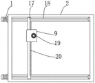
图1为本实用新型的整体主视图;Fig. 1 is the overall front view of the utility model;
图2为本实用新型的A处放大结构示意图;Fig. 2 is the enlarged structure schematic diagram of A place of the present utility model;
图3为本实用新型的整平辊安装结构示意图;3 is a schematic diagram of the installation structure of the leveling roller of the present invention;
图4为本实用新型的作业机架俯视图;Fig. 4 is the top view of the working frame of the utility model;
图5为本实用新型的齿轮结构示意图。FIG. 5 is a schematic diagram of the gear structure of the present invention.
图中:1、伺服电机;2、作业机架;3、工作台板;4、作业机柜;5、辊架;6、传动轴;7、固定导轨;8、移动导轮;9、控制盒;10、固定吊架;11、吸尘管;12、吸尘机嘴;13、吸尘风机;14、排尘管道;15、储尘盒;16、整平辊;17、驱动滑块;18、丝杠;19、正反转电机;20、齿条;21、齿轮。In the figure: 1. Servo motor; 2. Working frame; 3. Working table; 4. Working cabinet; 5. Roller frame; 6. Transmission shaft; 7. Fixed guide rail; 8. Moving guide wheel; 9. Control box ; 10, fixed hanger; 11, vacuum pipe; 12, vacuum nozzle; 13, vacuum fan; 14, dust exhaust pipe; 15, dust storage box; 16, leveling roller; 17, drive slider; 18, lead screw; 19, forward and reverse motor; 20, rack; 21, gear.
具体实施方式Detailed ways
下面将结合本实用新型实施例中的附图,对本实用新型实施例中的技术方案进行清楚、完整地描述,显然,所描述的实施例仅仅是本实用新型一部分实施例,而不是全部的实施例。The technical solutions in the embodiments of the present utility model will be clearly and completely described below with reference to the accompanying drawings in the embodiments of the present utility model. Obviously, the described embodiments are only a part of the embodiments of the present utility model, rather than all the implementations. example.
请参阅图1-5,本实用新型提供的一种实施例:一种表面处理用整平除杂装置,包括作业机架2和工作台板3,作业机架2安装在工作台板3的上方,作业机架2上安装有两个伺服电机1,伺服电机1的输出端通过转轴连接有丝杠18,丝杠18的表面安装有驱动滑块17,驱动滑块17之间焊接固定有齿条20,齿条20的上方设置有控制盒9,控制盒9的上端安装有正反转电机19,正反转电机19的输出端通过转轴与安装在控制盒9内部的齿轮21传动连接,齿轮21与齿条20之间通过啮合传动连接,控制盒9的下端安装有固定吊架10,固定吊架10上安装有吸尘风机13,工作台板3的两侧表面设置有固定导轨7,固定导轨7的内部通过移动导轮8连接有辊架5。Please refer to FIGS. 1-5 , an embodiment provided by the present utility model: a leveling and impurity removing device for surface treatment, comprising a
进一步,吸尘风机13的一端通过吸尘管11密封连接有吸尘机嘴12。Further, one end of the
进一步,吸尘风机13的另外一端通过排尘管道14密封连接有储尘盒15。Further, the other end of the
进一步,辊架5的两端通过传动轴6连接有整平辊16。Further, both ends of the
进一步,工作台板3的下方安装有作业机柜4,作业机柜4的前端表面设置有密封柜门。Further, a work cabinet 4 is installed below the
进一步,驱动滑块17沿丝杠18的表面水平滑动。Further, the
工作原理:使用时,作业机架2上安装有两个伺服电机1,伺服电机1的输出端通过转轴连接有丝杠18,丝杠18的表面安装有驱动滑块17,通过利用伺服电机1驱动丝杠18上的驱动滑块17做水平线性运动,驱动滑块17之间焊接固定有齿条20,齿条20的上方设置有控制盒9,控制盒9的上端安装有正反转电机19,正反转电机19的输出端通过转轴与安装在控制盒9内部的齿轮21传动连接,齿轮21与齿条20之间通过啮合传动连接,控制盒9的下端安装有固定吊架10,固定吊架10上安装有吸尘风机13,通过正反转电机19驱动控制盒9内部的齿轮21沿齿条20表面做啮合传动,进而促使控制盒9下方的吸尘风13可以对工作台板3表面放置的板材进行全面吸尘除杂处理,提高了除杂效率,工作台板3的两侧表面设置有固定导轨7,固定导轨7的内部通过移动导轮8连接有辊架5,辊架5的两端通过传动轴6连接有整平辊16,通过安装有可移动的辊架结构,在移动导轮8的作用下可沿固定导轨7做水平线性运动,进而可带动整平辊16对板材表面进行便捷式压实整平处理,具备操作方便的优点。Working principle: When in use, two
对于本领域技术人员而言,显然本实用新型不限于上述示范性实施例的细节,而且在不背离本实用新型的精神或基本特征的情况下,能够以其他的具体形式实现本实用新型。因此,无论从哪一点来看,均应将实施例看作是示范性的,而且是非限制性的,本实用新型的范围由所附权利要求而不是上述说明限定,因此旨在将落在权利要求的等同要件的含义和范围内的所有变化囊括在本实用新型内。不应将权利要求中的任何附图标记视为限制所涉及的权利要求。It will be apparent to those skilled in the art that the present invention is not limited to the details of the above-described exemplary embodiments, and that the present invention may be implemented in other specific forms without departing from the spirit or essential characteristics of the present invention. Therefore, the embodiments are to be considered in all respects as exemplary and not restrictive, and the scope of the present invention is defined by the appended claims rather than the foregoing description, and it is therefore intended that the All changes within the meaning and range of the required equivalents are embraced within the present invention. Any reference signs in the claims shall not be construed as limiting the involved claim.
Claims (6)
Priority Applications (1)
| Application Number | Priority Date | Filing Date | Title |
|---|---|---|---|
| CN202122857624.3U CN216460575U (en) | 2021-11-22 | 2021-11-22 | A leveling and impurity removing device for surface treatment |
Applications Claiming Priority (1)
| Application Number | Priority Date | Filing Date | Title |
|---|---|---|---|
| CN202122857624.3U CN216460575U (en) | 2021-11-22 | 2021-11-22 | A leveling and impurity removing device for surface treatment |
Publications (1)
| Publication Number | Publication Date |
|---|---|
| CN216460575U true CN216460575U (en) | 2022-05-10 |
Family
ID=81399485
Family Applications (1)
| Application Number | Title | Priority Date | Filing Date |
|---|---|---|---|
| CN202122857624.3U Active CN216460575U (en) | 2021-11-22 | 2021-11-22 | A leveling and impurity removing device for surface treatment |
Country Status (1)
| Country | Link |
|---|---|
| CN (1) | CN216460575U (en) |
-
2021
- 2021-11-22 CN CN202122857624.3U patent/CN216460575U/en active Active
Similar Documents
| Publication | Publication Date | Title |
|---|---|---|
| CN211992189U (en) | Electrical switch processing is with arc surface burring device | |
| CN209953312U (en) | Dust removal device for automobile filter | |
| CN110435029B (en) | Semiconductor material cutting device and method thereof | |
| CN110732930A (en) | A high-efficiency gear grinding device that improves the working environment | |
| CN219401431U (en) | Surface dust removing equipment for processing electronic main board | |
| CN221102730U (en) | Electrical cabinet drying device | |
| CN216225890U (en) | Cleaning device is used in production of graphite bipolar plate | |
| CN216539756U (en) | Plate cleaning device | |
| CN218837781U (en) | Novel clean mechanism of window cleaning robot | |
| CN217043900U (en) | A dust collector for photovoltaic power generation photovoltaic board | |
| CN212494339U (en) | A kind of dust removal equipment for copper plate processing | |
| CN211414326U (en) | Dustless workbench of numerical control machining center for green plate production | |
| CN213290903U (en) | A workstation for granite processing equipment | |
| CN219901647U (en) | A polishing device for wooden box processing | |
| CN212019841U (en) | Manipulator welding device | |
| CN220127508U (en) | A dust removal mechanism for a forging friction press | |
| CN220311913U (en) | Sheet metal cutting clamping device | |
| CN222095685U (en) | Rust removal device for steel pipe machining | |
| CN221984776U (en) | Polishing device with dust collecting mechanism | |
| CN211681301U (en) | Gear grinding equipment capable of reducing noise | |
| CN221640162U (en) | A machine tool manipulator moving device | |
| CN221966883U (en) | A cutting and cleaning device for steel structure processing | |
| CN221070071U (en) | High strength glass turning device | |
| CN214723239U (en) | Panel polishing trimming device | |
| CN218167898U (en) | High-efficient dust collector of electronic components |
Legal Events
| Date | Code | Title | Description |
|---|---|---|---|
| GR01 | Patent grant | ||
| GR01 | Patent grant |