CN216453028U - Can realize cutmixer of function of cutting mixing completely - Google Patents
Can realize cutmixer of function of cutting mixing completely Download PDFInfo
- Publication number
- CN216453028U CN216453028U CN202122232566.5U CN202122232566U CN216453028U CN 216453028 U CN216453028 U CN 216453028U CN 202122232566 U CN202122232566 U CN 202122232566U CN 216453028 U CN216453028 U CN 216453028U
- Authority
- CN
- China
- Prior art keywords
- motor
- rotating shaft
- box body
- chopping
- wall surface
- Prior art date
- Legal status (The legal status is an assumption and is not a legal conclusion. Google has not performed a legal analysis and makes no representation as to the accuracy of the status listed.)
- Expired - Fee Related
Links
Images



Landscapes
- Food-Manufacturing Devices (AREA)
- Crushing And Pulverization Processes (AREA)
Abstract
Description
技术领域technical field
本实用新型涉及斩拌机技术领域,具体为一种可实现完全斩拌功能的斩拌机。The utility model relates to the technical field of chopping machines, in particular to a chopping machine capable of realizing complete chopping and mixing functions.
背景技术Background technique
斩拌机刀速、锅速、斩刀与转锅的间隙达到最佳的组合,使斩切产品细度好、升温小、斩拌时间短,特别是由于乳化处理,使肠类产品的细密度与弹性大大增强,最大程度的提高了肉制品乳化效果、弹性及细腻度。The knife speed, pot speed, and the gap between the chopper and the pot can be optimally combined, so that the fineness of the chopped product is good, the temperature rise is small, and the chopping time is short. The density and elasticity are greatly enhanced, which maximizes the emulsification effect, elasticity and fineness of meat products.
斩拌机在斩拌过程中可能会存在斩拌效果不均匀的情况,公开号为CN206612113U的实用新型专利,提出一种用于制备肉丸的斩拌机,包括斩拌机主体,所述斩拌机主体的上方设置有转锅,所述转锅一侧的斩拌机主体上通过转轴安装有半圆锅盖,所述斩拌机主体上安装有第一伺服电机,所述第一伺服电机的输出轴通过传动轴连接有旋转斩刀,所述转锅远离半圆锅盖的一侧的斩拌机主体设置有出料口,所述出料口一侧的斩拌机主体设置有支架。本实用新型中采用两组J型搅拌片进行搅拌,使得转锅侧壁上沾附的原料能够被被刮下,使得原料搅拌均匀,提高肉丸成品的品质,同时,弧形挡料板能够挡住原料飞溅的路径,并使得飞溅的原料从弧形挡料板上滑落至转锅中继续进行加工,避免了原料的浪费,降低了生产成本。然而该装置虽然能够对食品进行斩拌。但该装置不具备调整肉品位置的机构,由于在斩拌过程中,肉品在斩刀单向切割的作用下会残留至加工盘内部边缘处,使斩刀无法完全切割。In the process of chopping and mixing, the chopping and mixing machine may have uneven chopping and mixing effect. The utility model patent publication number CN206612113U proposes a chopping and mixing machine for preparing meatballs, including a chopping and mixing machine main body. A rotating pot is arranged above the main body of the mixing machine, a semicircular pot cover is installed on the main body of the chopping machine on one side of the rotating pot through a rotating shaft, a first servo motor is installed on the main body of the chopping machine, and the first servo motor The output shaft is connected with a rotary chopper through the transmission shaft, the chopper main body on the side of the rotary pot away from the semicircular pot cover is provided with a discharge port, and the chopper main body on the side of the discharge port is provided with a bracket. In the utility model, two sets of J-shaped stirring blades are used for stirring, so that the raw materials adhering to the side wall of the rotating pot can be scraped off, so that the raw materials can be stirred evenly, and the quality of the finished meatballs can be improved. The splashing path of the raw material is blocked, and the splashed raw material slides from the arc baffle plate to the rotating pot for continuous processing, thereby avoiding the waste of raw materials and reducing the production cost. However, although the device can chop and stir the food. However, this device does not have a mechanism for adjusting the position of the meat, because during the chopping and mixing process, the meat will remain on the inner edge of the processing plate under the action of one-way cutting by the chopping knife, so that the chopping knife cannot be completely cut.
实用新型内容Utility model content
针对现有技术的不足,本实用新型提供了一种可实现完全斩拌功能的斩拌机,解决了不具备调整肉品位置的机构的问题。Aiming at the deficiencies of the prior art, the utility model provides a chopping machine that can realize a complete chopping and mixing function, which solves the problem of not having a mechanism for adjusting the position of the meat.
为实现以上目的,本实用新型通过以下技术方案予以实现:一种可实现完全斩拌功能的斩拌机,包括箱体,所述箱体内部下壁面设有第一电机,所述第一电机驱动端连接有第一转轴,所述第一转轴顶部连接有加工盘,所述加工盘上壁面中心处活动连接有中心柱,所述箱体一侧壁面连接有顶盖,所述顶盖位于所述加工盘上方一侧,所述顶盖上壁面设有齿壳,所述箱体两侧均固定安装有支撑架,所述支撑架顶部设有往复机构,所述箱体一侧设有收集机构。In order to achieve the above purpose, the present utility model is achieved through the following technical solutions: a chopping machine that can realize a complete chopping and mixing function, including a box body, and a first motor is provided on the lower wall surface of the box body, and the first motor The driving end is connected with a first rotating shaft, the top of the first rotating shaft is connected with a processing disk, a center column is movably connected at the center of the upper wall surface of the processing disk, and a top cover is connected with a side wall surface of the box body, and the top cover is located at the center of the upper wall surface of the processing disk. On the upper side of the processing plate, the upper wall of the top cover is provided with a toothed casing, the two sides of the box body are fixedly installed with support frames, the top of the support frame is provided with a reciprocating mechanism, and one side of the box body is provided with a reciprocating mechanism. collection agency.
优选的,所述往复机构包括第二电机,所述第二电机驱动端连接有转盘,所述转盘一侧壁面铰接有第一连杆,所述第一连杆末端铰接有第二连杆,所述第二连杆末端连接有第三电机,所述加工盘侧壁面两侧均开有滑孔,所述第三电机驱动端连接有第二转轴,所述第二转轴一端设有推叶,所述第二转轴滑动于所述滑孔内。Preferably, the reciprocating mechanism includes a second motor, the driving end of the second motor is connected with a turntable, a side wall of the turntable is hinged with a first link, and the end of the first link is hinged with a second link, A third motor is connected to the end of the second connecting rod, sliding holes are opened on both sides of the side wall surface of the processing disc, the driving end of the third motor is connected to a second rotating shaft, and one end of the second rotating shaft is provided with a push blade , the second rotating shaft slides in the sliding hole.
优选的,所述收集机构包括第四电机,所述第四电机设于所述箱体一侧,所述第四电机驱动端连接有螺纹杆,所述螺纹杆顶部旋接有内螺纹套筒,所述内螺纹套筒一侧安装有连接架,所述连接架一端设有限位销,所述中心柱一侧开有限位槽,所述限位销滑动连接于所述限位槽内,所述连接架下壁面连接有一对中间杆,一对所述中间杆底部间连接有收集箱,所述收集箱截面与所述加工盘截面相同。Preferably, the collecting mechanism includes a fourth motor, the fourth motor is arranged on one side of the box, a threaded rod is connected to the driving end of the fourth motor, and an inner threaded sleeve is screwed on the top of the threaded rod , a connecting frame is installed on one side of the inner threaded sleeve, one end of the connecting frame is provided with a limit pin, a limit groove is opened on one side of the central column, and the limit pin is slidably connected in the limit groove, A pair of intermediate rods are connected to the lower wall of the connecting frame, a collection box is connected between the bottoms of the pair of intermediate rods, and the cross-section of the collection box is the same as the cross-section of the processing disc.
优选的,所述箱体一侧壁面固定安装有支架,所述支架顶部固定安装有第五电机驱动端连接有第三转轴,所述第三转轴活动连接于所述顶盖侧壁面,所述第三转轴一端连接有斩刀,所述斩刀位于所述齿壳内。Preferably, a bracket is fixedly installed on a side wall of the box body, a fifth motor drive end is fixedly installed on the top of the bracket and is connected to a third rotating shaft, the third rotating shaft is movably connected to the side wall surface of the top cover, and the A chopper is connected to one end of the third rotating shaft, and the chopper is located in the tooth housing.
优选的,所述收集箱下壁面滑动于所述加工盘内壁面。Preferably, the lower wall surface of the collection box slides on the inner wall surface of the processing tray.
优选的,所述螺纹杆顶部设有限位块。Preferably, a limit block is provided on the top of the threaded rod.
优选的,所述推叶围绕于所述第二转轴一侧,且具有螺旋结构。Preferably, the push vane surrounds one side of the second rotating shaft and has a helical structure.
有益效果beneficial effect
本实用新型提供了一种可实现完全斩拌功能的斩拌机,具备以下有益效果:本装置结构紧凑,通过斩刀对肉品在加工盘内进行斩拌,由于斩刀对肉品进行单向斩拌,肉品在斩刀作用下堆积在加工盘内部边缘处,使斩刀无法完全进行斩拌,本装置内通过第二电机驱动端的转盘使第一连杆转动,并使第二连杆往复滑动,并使第三电机进行往复运动,使第二转轴,使缠绕于第二转轴一半侧壁面的螺旋结构的推叶将肉品向加工盘中心处推动,使肉品被完全加工,给人们带来了方便。The utility model provides a chopping machine that can realize the function of completely chopping and mixing, and has the following beneficial effects: the device has a compact structure, and the meat is chopped and mixed in the processing plate by the chopping knife. In the direction of chopping and mixing, the meat products are piled up on the inner edge of the processing plate under the action of the chopping knife, so that the chopping knife cannot completely chopping and mixing. The rod slides back and forth, and makes the third motor reciprocate, so that the second rotating shaft makes the pusher of the helical structure wrapped around the half side wall of the second rotating shaft to push the meat to the center of the processing plate, so that the meat is completely processed. Bring convenience to people.
附图说明Description of drawings
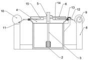
图1为本实用新型主视示意图。Figure 1 is a schematic front view of the utility model.
图2为本实用新型内部结构示意图。Figure 2 is a schematic diagram of the internal structure of the utility model.
图3为本实用新型收集箱结构示意图。Figure 3 is a schematic structural diagram of the collection box of the present invention.
图4为本实用新型加工盘俯视示意图。FIG. 4 is a schematic top view of the processing disc of the present invention.
图5为本实用新型斩刀示意图。FIG. 5 is a schematic diagram of the cutting knife of the present invention.
图6为本实用新型第二电机示意图6 is a schematic diagram of the second motor of the present invention
图中:1、箱体;2、第一电机;3、第一转轴;4、加工盘;5、中心柱;6、顶盖;7、齿壳;8、支撑架;9、第二电机;10、转盘;11、第一连杆;12、第二连杆;13、第三电机;14、第二转轴;15、推叶;16、第四电机;17、螺纹杆;18、内螺纹套筒;19、连接架;20、限位销;21、限位槽;22、收集箱;23、第五电机;24、第三转轴;25、斩刀。In the figure: 1. Box body; 2. The first motor; 3. The first rotating shaft; 4. The processing plate; 5. The central column; 6. The top cover; ; 10, turntable; 11, the first connecting rod; 12, the second connecting rod; 13, the third motor; 14, the second shaft; 15, the pusher blade; 16, the fourth motor; 17, the threaded rod; 18, the inner Threaded sleeve; 19, connecting frame; 20, limit pin; 21, limit slot; 22, collection box; 23, fifth motor; 24, third shaft; 25, chopper.
具体实施方式Detailed ways
下面将结合本实用新型实施例中的附图,对本实用新型实施例中的技术方案进行清楚、完整地描述,显然,所描述的实施例仅仅是本实用新型一部分实施例,而不是全部的实施例。基于本实用新型中的实施例,本领域普通技术人员在没有做出创造性劳动前提下所获得的所有其他实施例,都属于本实用新型保护的范围。The technical solutions in the embodiments of the present utility model will be clearly and completely described below with reference to the accompanying drawings in the embodiments of the present utility model. Obviously, the described embodiments are only a part of the embodiments of the present utility model, rather than all the implementations. example. Based on the embodiments of the present invention, all other embodiments obtained by those of ordinary skill in the art without creative work fall within the protection scope of the present invention.
请参阅图1-6,一种可实现完全斩拌功能的斩拌机,包括箱体1,所述箱体1内部下壁面设有第一电机2,所述第一电机2驱动端连接有第一转轴3,所述第一转轴3顶部连接有加工盘4,所述加工盘4上壁面中心处活动连接有中心柱5,所述箱体1一侧壁面连接有顶盖6,所述顶盖6位于所述加工盘4上方一侧,所述顶盖6上壁面设有齿壳7,所述箱体1两侧均固定安装有支撑架8,所述支撑架8顶部设有往复机构,所述箱体1一侧设有收集机构,所述往复机构包括第二电机9,所述第二电机9驱动端连接有转盘10,所述转盘10一侧壁面铰接有第一连杆11,所述第一连杆11末端铰接有第二连杆12,所述第二连杆12末端连接有第三电机13,所述加工盘4侧壁面两侧均开有滑孔,所述第三电机13驱动端连接有第二转轴14,所述第二转轴14一端设有推叶15,所述第二转轴14滑动于所述滑孔内,所述收集机构包括第四电机16,所述第四电机16设于所述箱体1一侧,所述第四电机16驱动端连接有螺纹杆17,所述螺纹杆17顶部旋接有内螺纹套筒18,所述内螺纹套筒18一侧安装有连接架19,所述连接架19一端设有限位销20,所述中心柱5一侧开有限位槽21,所述限位销20滑动连接于所述限位槽21内,所述连接架19下壁面连接有一对中间杆,一对所述中间杆底部间连接有收集箱22,所述收集箱22截面与所述加工盘4截面相同,所述箱体1一侧壁面固定安装有支架,所述支架顶部固定安装有第五电机23驱动端连接有第三转轴24,所述第三转轴24活动连接于所述顶盖6侧壁面,所述第三转轴24一端连接有斩刀25,所述斩刀25位于所述齿壳7内,所述收集箱22下壁面滑动于所述加工盘4内壁面,所述螺纹杆17顶部设有限位块,所述推叶15围绕于所述第二转轴14一侧,且具有螺旋结构。Please refer to FIGS. 1-6 , a chopping machine that can realize complete chopping and mixing function includes a box body 1 , a
实施例:将肉品放入至加工盘4内,控制第一电机2驱动端转动,此时加工盘4转动,并控制第五电机23驱动端的第三转轴24旋转,此时第三转轴24一端的推叶15转动,由于推叶15缠绕于第三转轴24半侧,控制第二电机9转动,此时第一连杆11转动,此时第二连杆12进行往复运动,使第二连杆12一端的第三电机13进行往复运动,此时第二转轴14在自转的同时进行往复滑动,在第二转轴14向加工盘4中心处进给时,推叶15转动至第二转轴14下方,并将肉品从加工盘4边缘处推至加工盘4中心一侧,随后第二转轴14向加工盘4边缘处运动时,推叶15转至第二转轴14上方,不会将肉品刮回边缘处,斩拌完毕后,控制第四电机16驱动端转动,使螺纹杆17转动,最终使内螺纹套筒18在螺纹杆17上进行移动,使限位销20滑动于限位槽21内滑动,并使收集箱22位于加工盘4上壁面肉品进入至收集箱22内,完成收集,使用简单。Example: put the meat product into the
需要说明的是,在本文中,诸如第一和第二等之类的关系术语仅仅用来将一个实体或者操作与另一个实体或操作区分开来,而不一定要求或者暗示这些实体或操作之间存在任何这种实际的关系或者顺序。而且,术语“包括”、“包含”或者其任何其他变体意在涵盖非排他性的包含,从而使得包括一系列要素的过程、方法、物品或者设备不仅包括那些要素,而且还包括没有明确列出的其他要素,或者是还包括为这种过程、方法、物品或者设备所固有的要素。在没有更多限制的情况下。由语句“包括一个......限定的要素,并不排除在包括所述要素的过程、方法、物品或者设备中还存在另外的相同要素”。It should be noted that, in this document, relational terms such as first and second are only used to distinguish one entity or operation from another entity or operation, and do not necessarily require or imply any relationship between these entities or operations. any such actual relationship or sequence exists. Moreover, the terms "comprising", "comprising" or any other variation thereof are intended to encompass non-exclusive inclusion such that a process, method, article or device comprising a list of elements includes not only those elements, but also includes not explicitly listed or other elements inherent to such a process, method, article or apparatus. without more restrictions. An element defined by the phrase "comprising an... does not preclude the presence of additional identical elements in a process, method, article or apparatus comprising said element".
尽管已经示出和描述了本实用新型的实施例,对于本领域的普通技术人员而言,可以理解在不脱离本实用新型的原理和精神的情况下可以对这些实施例进行多种变化、修改、替换和变型,本实用新型的范围由所附权利要求及其等同物限定。Although the embodiments of the present invention have been shown and described, it will be understood by those skilled in the art that various changes and modifications can be made to these embodiments without departing from the principles and spirit of the present invention , alternatives and modifications, the scope of the present invention is defined by the appended claims and their equivalents.
Claims (7)
Priority Applications (1)
| Application Number | Priority Date | Filing Date | Title |
|---|---|---|---|
| CN202122232566.5U CN216453028U (en) | 2021-09-15 | 2021-09-15 | Can realize cutmixer of function of cutting mixing completely |
Applications Claiming Priority (1)
| Application Number | Priority Date | Filing Date | Title |
|---|---|---|---|
| CN202122232566.5U CN216453028U (en) | 2021-09-15 | 2021-09-15 | Can realize cutmixer of function of cutting mixing completely |
Publications (1)
| Publication Number | Publication Date |
|---|---|
| CN216453028U true CN216453028U (en) | 2022-05-10 |
Family
ID=81437029
Family Applications (1)
| Application Number | Title | Priority Date | Filing Date |
|---|---|---|---|
| CN202122232566.5U Expired - Fee Related CN216453028U (en) | 2021-09-15 | 2021-09-15 | Can realize cutmixer of function of cutting mixing completely |
Country Status (1)
| Country | Link |
|---|---|
| CN (1) | CN216453028U (en) |
-
2021
- 2021-09-15 CN CN202122232566.5U patent/CN216453028U/en not_active Expired - Fee Related
Similar Documents
| Publication | Publication Date | Title |
|---|---|---|
| CN205129974U (en) | Electronic section device that shreds | |
| CN208695211U (en) | Meat mincer is used in a kind of processing of pork | |
| CN208147930U (en) | Capsicum shredding machine | |
| CN105234974B (en) | Double-knife continuous chopping machine | |
| CN118269162B (en) | Crushing device and crushing process for traditional Chinese medicine decoction piece production | |
| CN111227015B (en) | A beef processing chopping machine and using method thereof | |
| CN211537347U (en) | A funnel-type meat floss batching device | |
| CN222490420U (en) | Meat products processing cooking machine | |
| CN101716774B (en) | Automatic food slicing and shredding machine | |
| CN220512132U (en) | A kind of extrusion equipment for cereal puffed food with high resistant starch content | |
| CN216419656U (en) | Integrated pork food chopping and guiding device | |
| CN212348983U (en) | A new type of chopper | |
| CN220174319U (en) | Food chopping machine convenient for uniform chopping | |
| CN111805602B (en) | Shredding device for kitchen | |
| CN110637864B (en) | A new type of chopper | |
| CN209718367U (en) | A kind of high efficiency crusher | |
| CN220274731U (en) | Stable chopping mixer | |
| CN216630457U (en) | Liquid dispersion machine with temperature control function | |
| CN220573645U (en) | A chopping device for sausage raw material processing | |
| CN223542844U (en) | A grind mixing device for sesame paste production | |
| CN219273234U (en) | Vertical chopper mixer with wall built-up preventing structure | |
| CN223324441U (en) | Mixing arrangement is used in shrimp condiment processing | |
| CN112021377B (en) | Meat supplied material chopping and forming device | |
| CN216566196U (en) | A stainless steel meat grinder with intelligent anti-blocking function for meat processing | |
| CN220779798U (en) | Totally-enclosed soft powder production device |
Legal Events
| Date | Code | Title | Description |
|---|---|---|---|
| GR01 | Patent grant | ||
| GR01 | Patent grant | ||
| CF01 | Termination of patent right due to non-payment of annual fee | ||
| CF01 | Termination of patent right due to non-payment of annual fee |
Granted publication date: 20220510 |