CN216431016U - An intelligent management platform for smart classrooms - Google Patents
An intelligent management platform for smart classrooms Download PDFInfo
- Publication number
- CN216431016U CN216431016U CN202123055611.0U CN202123055611U CN216431016U CN 216431016 U CN216431016 U CN 216431016U CN 202123055611 U CN202123055611 U CN 202123055611U CN 216431016 U CN216431016 U CN 216431016U
- Authority
- CN
- China
- Prior art keywords
- base
- groove
- fixedly installed
- management platform
- intelligent management
- Prior art date
- Legal status (The legal status is an assumption and is not a legal conclusion. Google has not performed a legal analysis and makes no representation as to the accuracy of the status listed.)
- Expired - Fee Related
Links
- 238000009434 installation Methods 0.000 claims abstract description 32
- 230000005540 biological transmission Effects 0.000 claims abstract description 16
- 230000002457 bidirectional effect Effects 0.000 claims abstract description 13
- 238000010586 diagram Methods 0.000 description 3
- 230000009286 beneficial effect Effects 0.000 description 2
- 238000012986 modification Methods 0.000 description 2
- 230000004048 modification Effects 0.000 description 2
- 230000006870 function Effects 0.000 description 1
- 238000000034 method Methods 0.000 description 1
Images


Landscapes
- Accommodation For Nursing Or Treatment Tables (AREA)
Abstract
本实用新型公开了一种智慧教室的智能管理平台,包括底座和计算机本体,所述底座的下表面开设有安装槽,底座的内部开设有安装腔,安装腔的内顶壁转动连接有延伸至安装槽内部的螺纹杆,底座的侧面开设有延伸至安装腔内部的转动开口,转动开口的内壁转动连接有传动杆,传动杆的一端固定连接有操作块。该智慧教室的智能管理平台,通过设置电机和支撑板,电机的运转通过第二锥形齿轮带动双向螺纹杆转动,两个螺纹块在双向螺纹杆的转动下带动挡板进行移动直至打开收纳槽,在电动液压杆的作用下带动支撑板通过安装架和第二滑块进行升降运动,支撑板的上升将计算机本体托举至置物板的上表面,使该讲桌能够达到对计算机进行收纳的目的。
The utility model discloses an intelligent management platform for a smart classroom, which comprises a base and a computer body. An installation groove is formed on the lower surface of the base, an installation cavity is formed in the interior of the base, and an inner top wall of the installation cavity is rotatably connected to a The threaded rod inside the installation groove, the side of the base is provided with a rotation opening extending to the interior of the installation cavity, the inner wall of the rotation opening is rotatably connected with a transmission rod, and one end of the transmission rod is fixedly connected with an operation block. The intelligent management platform of the smart classroom is equipped with a motor and a support plate. The operation of the motor drives the bidirectional threaded rod to rotate through the second bevel gear, and the two threaded blocks drive the baffle to move under the rotation of the bidirectional threaded rod until the storage slot is opened. , under the action of the electro-hydraulic rod, the support plate is driven to move up and down through the mounting frame and the second slider, and the rise of the support plate lifts the computer body to the upper surface of the storage board, so that the desk can store the computer. Purpose.
Description
技术领域technical field
本实用新型涉及智慧教室技术领域,具体为一种智慧教室的智能管理平台。The utility model relates to the technical field of intelligent classrooms, in particular to an intelligent management platform for intelligent classrooms.
背景技术Background technique
智慧教室是数字教室和未来教室的一种形式。智慧教室是一种新型的教育形式,有别于传统授听课方式;课前学生提前预习,课中学习分组讨论,随时测试,教师能快速掌握每位学生学习情况,并进行针对性指导。Smarter classrooms are a form of digital classrooms and future classrooms. Smarter classroom is a new type of education, which is different from the traditional way of teaching and listening. Students preview before class, group discussions during class, and tests at any time. Teachers can quickly grasp the learning situation of each student and provide targeted guidance.
教师再通过智慧教室对学生进行教学时通常需要使用讲桌对计算机以及一些教学器具进行放置,但是,现有的讲桌大多结构单一,不具备对计算机进行收纳的功能,减少了桌面的可用面积,降低了其实用性。When teachers teach students through smart classrooms, they usually need to use desks to place computers and some teaching equipment. However, most of the existing desks have a single structure and do not have the function of storing computers, reducing the usable area of the desktop. , reducing its usefulness.
因此我们提出一种智慧教室的智能管理平台。Therefore, we propose an intelligent management platform for smarter classrooms.
实用新型内容Utility model content
本实用新型的目的在于提供一种智慧教室的智能管理平台,以解决上述背景技术中提出的问题。The purpose of the present invention is to provide an intelligent management platform for a smart classroom to solve the problems raised in the above background technology.
为实现上述目的,本实用新型提供如下技术方案:一种智慧教室的智能管理平台,包括底座和计算机本体,所述底座的下表面开设有安装槽,底座的内部开设有安装腔,安装腔的内顶壁转动连接有延伸至安装槽内部的螺纹杆,底座的侧面开设有延伸至安装腔内部的转动开口,转动开口的内壁转动连接有传动杆,传动杆的一端固定连接有操作块,螺纹杆的表面螺纹连接有螺纹筒,螺纹筒的下端固定安装有万向轮,螺纹筒的表面设置有第一滑块,安装槽的内壁开设有与第一滑块相适配的第一滑槽,底座的上表面固定安装有置物板,置物板的上表面开设有滑动槽,滑动槽的内后壁开设有滑轨,滑轨的内壁通过滑块滑动连接有相对应的两个挡板,置物板的板体内部开设有操作槽,操作槽的两侧内壁转动连接有双向螺纹杆,置物板的正面固定安装有安装盒,安装盒的内部固定安装有电机,电机的输出轴延伸至操作槽的内部,双向螺纹杆的表面螺纹连接有相对应的两个螺纹块,两个螺纹块的背面分别与两个挡板的正面固定连接,滑动槽的内底壁开设有延伸至底座内部的收纳槽,收纳槽的内底壁固定安装有电动液压杆,电动液压杆的伸缩端固定安装有支撑板,支撑板的下表面固定安装有相对应的两个支撑架,支撑架的表面设置有第二滑块,收纳槽的内前壁与内后壁均开设有与第二滑块相适配的第二滑槽。In order to achieve the above purpose, the present invention provides the following technical solutions: an intelligent management platform for a smart classroom, comprising a base and a computer body, an installation groove is formed on the lower surface of the base, an installation cavity is opened inside the base, and the installation cavity is provided with an installation cavity. The inner top wall is rotatably connected with a threaded rod extending to the inside of the installation groove, the side of the base is provided with a rotation opening extending into the interior of the installation cavity, the inner wall of the rotation opening is rotatably connected with a transmission rod, and one end of the transmission rod is fixedly connected with an operating block, the thread The surface of the rod is threadedly connected with a threaded barrel, the lower end of the threaded barrel is fixedly installed with a universal wheel, the surface of the threaded barrel is provided with a first sliding block, and the inner wall of the installation groove is provided with a first sliding groove matching the first sliding block The upper surface of the base is fixedly installed with a storage board, the upper surface of the storage board is provided with a sliding groove, the inner rear wall of the sliding groove is provided with a sliding rail, and the inner wall of the sliding rail is slidably connected with two corresponding baffles through the slider. There is an operation slot inside the board body of the storage board, and two-way threaded rods are rotatably connected to the inner walls of the two sides of the operation slot. Inside the groove, the surface of the two-way threaded rod is threadedly connected with two corresponding threaded blocks, the backs of the two threaded blocks are respectively fixedly connected with the fronts of the two baffles, and the inner bottom wall of the sliding groove is provided with extending to the inside of the base. The receiving groove, the inner bottom wall of the receiving groove is fixedly installed with an electro-hydraulic rod, the telescopic end of the electro-hydraulic rod is fixedly installed with a support plate, the lower surface of the support plate is fixedly installed with two corresponding support frames, and the surface of the support frame is provided with For the second sliding block, the inner front wall and the inner rear wall of the receiving groove are both provided with a second sliding groove which is matched with the second sliding block.
优选的,所述安装槽的数量为四个,四个安装槽呈矩形阵列设置在底座的下表面。Preferably, the number of the installation grooves is four, and the four installation grooves are arranged in a rectangular array on the lower surface of the base.
优选的,所述螺纹杆的表面与传动杆的另一端均固定安装有第一锥形齿轮,两个第一锥形齿轮相啮合。Preferably, a first bevel gear is fixedly installed on the surface of the threaded rod and the other end of the transmission rod, and the two first bevel gears are engaged with each other.
优选的,所述操作块的表面开设有六棱槽,六棱槽与外部六棱扳手相适配。Preferably, the surface of the operation block is provided with a hexagonal groove, and the hexagonal groove is adapted to the external hexagonal wrench.
优选的,所述双向螺纹杆的表面与电机输出轴的端部均固定安装有第二锥形齿轮,两个第二锥形齿轮相啮合。Preferably, a second bevel gear is fixedly installed on the surface of the bidirectional threaded rod and the end of the output shaft of the motor, and the two second bevel gears are engaged with each other.
优选的,所述底座的背面设置有控制器,控制器分别与电机和电动液压杆信号连接。Preferably, a controller is provided on the back of the base, and the controller is signal-connected to the motor and the electro-hydraulic rod respectively.
有益效果beneficial effect
本实用新型提供了一种智慧教室的智能管理平台,具备以下有益效果:The utility model provides an intelligent management platform for a smart classroom, which has the following beneficial effects:
1.该智慧教室的智能管理平台,通过设置挡板、电机、电动液压杆和支撑板,当需要使用计算机时,通过控制器控制电机运转,电机的运转通过第二锥形齿轮带动双向螺纹杆转动,两个螺纹块在双向螺纹杆的转动下带动挡板进行移动直至打开收纳槽,在电动液压杆的作用下带动支撑板通过安装架和第二滑块进行升降运动,支撑板的上升将计算机本体托举至置物板的上表面,当需要将计算机本体进行收纳时,通过控制器控制电动液压杆回缩即可,使该讲桌能够达到对计算机进行收纳的目的,提高了该讲桌的实用性。1. The intelligent management platform of the smart classroom is equipped with baffles, motors, electro-hydraulic rods and support plates. When a computer is needed, the motor is controlled by the controller to run, and the motor runs through the second bevel gear to drive the bidirectional threaded rod. Rotating, the two threaded blocks drive the baffle to move under the rotation of the two-way threaded rod until the receiving slot is opened, and under the action of the electro-hydraulic rod, the support plate is driven to move up and down through the mounting frame and the second slider, and the rise of the support plate will The computer body is lifted to the upper surface of the storage board. When the computer body needs to be stored, the controller can control the electric hydraulic rod to retract, so that the desk can achieve the purpose of storing the computer and improve the performance of the desk. practicability.
2.该智慧教室的智能管理平台,通过设置螺纹杆、螺纹筒、操作块和万向轮,使用六棱扳手通过六棱槽带动操作块转动,操作块的转动带动传动杆转动,传动杆的转动通过第一锥形齿轮带动螺纹杆转动,螺纹筒在螺纹杆的转动下通过第一滑块进行升降运动,螺纹筒的下降带动万向轮将该讲桌顶起并支撑,在万向轮的作用下为该讲桌的转运工作提供便捷。2. The intelligent management platform of the smart classroom uses a threaded rod, a threaded cylinder, an operation block and a universal wheel, and uses a hexagonal wrench to drive the operation block to rotate through the hexagonal groove. The rotation drives the threaded rod to rotate through the first bevel gear, and the threaded barrel moves up and down through the first slider under the rotation of the threaded rod. The descending of the threaded barrel drives the universal wheel to lift up and support the desk. Under the action of the lectern, it provides convenience for the transfer of the desk.
附图说明Description of drawings
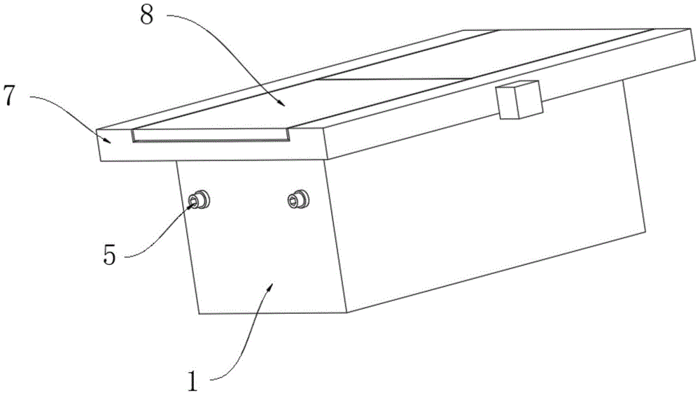
图1为本实用新型立体结构示意图;1 is a schematic diagram of the three-dimensional structure of the present utility model;
图2为本实用新型正剖结构示意图;2 is a schematic diagram of the front section of the utility model;
图3为本实用新型侧剖结构示意图;Figure 3 is a schematic diagram of a side sectional structure of the present utility model;
图4为本实用新型图3中A处放大结构示意图。FIG. 4 is an enlarged schematic view of the structure at A in FIG. 3 of the present utility model.
图中:1底座、2计算机本体、3螺纹杆、4传动杆、5操作块、6螺纹筒、7置物板、8挡板、9双向螺纹杆、10电机、11螺纹块、12电动液压杆、13支撑板、14第一锥形齿轮、15第二锥形齿轮、16控制器。In the picture: 1 base, 2 computer body, 3 threaded rods, 4 transmission rods, 5 operating blocks, 6 threaded barrels, 7 storage boards, 8 baffles, 9 two-way threaded rods, 10 motors, 11 threaded blocks, 12 electro-hydraulic rods , 13 support plate, 14 first bevel gear, 15 second bevel gear, 16 controller.
具体实施方式Detailed ways
下面将结合本实用新型实施例中的附图,对本实用新型实施例中的技术方案进行清楚、完整地描述,显然,所描述的实施例仅仅是本实用新型一部分实施例,而不是全部的实施例。基于本实用新型中的实施例,本领域普通技术人员在没有做出创造性劳动前提下所获得的所有其他实施例,都属于本实用新型保护的范围。The technical solutions in the embodiments of the present utility model will be clearly and completely described below with reference to the accompanying drawings in the embodiments of the present utility model. Obviously, the described embodiments are only a part of the embodiments of the present utility model, rather than all the implementations. example. Based on the embodiments of the present invention, all other embodiments obtained by those of ordinary skill in the art without creative work fall within the protection scope of the present invention.
请参阅图1-4,本实用新型提供一种技术方案:一种智慧教室的智能管理平台,包括底座1和计算机本体2,底座1的下表面开设有安装槽,安装槽的数量为四个,四个安装槽呈矩形阵列设置在底座1的下表面,底座1的内部开设有安装腔,安装腔的内顶壁转动连接有延伸至安装槽内部的螺纹杆3,底座1的侧面开设有延伸至安装腔内部的转动开口,转动开口的内壁转动连接有传动杆4,传动杆4的一端固定连接有操作块5,螺纹杆3的表面与传动杆4的另一端均固定安装有第一锥形齿轮14,两个第一锥形齿轮14相啮合,操作块5的表面开设有六棱槽,六棱槽与外部六棱扳手相适配,螺纹杆3的表面螺纹连接有螺纹筒6,螺纹筒6的下端固定安装有万向轮,螺纹筒6的表面设置有第一滑块,安装槽的内壁开设有与第一滑块相适配的第一滑槽。1-4, the present utility model provides a technical solution: an intelligent management platform for a smart classroom, including a
通过设置螺纹杆3、螺纹筒6、操作块5和万向轮,使用六棱扳手通过六棱槽带动操作块5转动,操作块5的转动带动传动杆4转动,传动杆4的转动通过第一锥形齿轮14带动螺纹杆3转动,螺纹筒6在螺纹杆3的转动下通过第一滑块进行升降运动,螺纹筒6的下降带动万向轮将该讲桌顶起并支撑,在万向轮的作用下为该讲桌的转运工作提供便捷。By setting the threaded
底座1的上表面固定安装有置物板7,置物板7的上表面开设有滑动槽,滑动槽的内后壁开设有滑轨,滑轨的内壁通过滑块滑动连接有相对应的两个挡板8,置物板7的板体内部开设有操作槽,操作槽的两侧内壁转动连接有双向螺纹杆9,置物板7的正面固定安装有安装盒,安装盒的内部固定安装有电机10,电机10的输出轴延伸至操作槽的内部,双向螺纹杆9的表面与电机10输出轴的端部均固定安装有第二锥形齿轮15,两个第二锥形齿轮15相啮合,双向螺纹杆9的表面螺纹连接有相对应的两个螺纹块11,两个螺纹块11的背面分别与两个挡板8的正面固定连接。The upper surface of the
滑动槽的内底壁开设有延伸至底座1内部的收纳槽,收纳槽的内底壁固定安装有电动液压杆12,底座1的背面设置有控制器16,控制器16分别与电机10和电动液压杆12信号连接,电动液压杆12的伸缩端固定安装有支撑板13,支撑板13的下表面固定安装有相对应的两个支撑架,支撑架的表面设置有第二滑块,收纳槽的内前壁与内后壁均开设有与第二滑块相适配的第二滑槽。The inner bottom wall of the sliding groove is provided with a receiving groove extending to the inside of the
通过设置挡板8、电机10、电动液压杆12和支撑板13,当需要使用计算机时,通过控制器16控制电机10运转,电机10的运转通过第二锥形齿轮15带动双向螺纹杆9转动,两个螺纹块11在双向螺纹杆9的转动下带动挡板8进行移动直至打开收纳槽,在电动液压杆12的作用下带动支撑板13通过安装架和第二滑块进行升降运动,支撑板13的上升将计算机本体2托举至置物板7的上表面,当需要将计算机本体2进行收纳时,通过控制器16控制电动液压杆12回缩即可,使该讲桌能够达到对计算机进行收纳的目的,提高了该讲桌的实用性。By setting the
工作原理:在使用该装置时,当需要使用计算机时,通过控制器16控制电机10运转,电机10的运转通过第二锥形齿轮15带动双向螺纹杆9转动,两个螺纹块11在双向螺纹杆9的转动下带动挡板8进行移动直至打开收纳槽,在电动液压杆12的作用下带动支撑板13通过安装架和第二滑块进行升降运动,支撑板13的上升将计算机本体2托举至置物板7的上表面,当需要将计算机本体2进行收纳时,通过控制器16控制电动液压杆12回缩即可,使该讲桌能够达到对计算机进行收纳的目的,当需要对该讲桌进行转运工作时,使用六棱扳手通过六棱槽带动操作块5转动,操作块5的转动带动传动杆4转动,传动杆4的转动通过第一锥形齿轮14带动螺纹杆3转动,螺纹筒6在螺纹杆3的转动下通过第一滑块进行升降运动,螺纹筒6的下降带动万向轮将该讲桌顶起并支撑,在万向轮的作用下为该讲桌的转运工作提供便捷。Working principle: When using the device, when the computer needs to be used, the
尽管已经示出和描述了本实用新型的实施例,对于本领域的普通技术人员而言,可以理解在不脱离本实用新型的原理和精神的情况下可以对这些实施例进行多种变化、修改、替换和变型,本实用新型的范围由所附权利要求及其等同物限定。Although the embodiments of the present invention have been shown and described, it will be understood by those skilled in the art that various changes and modifications can be made to these embodiments without departing from the principles and spirit of the present invention , alternatives and modifications, the scope of the present invention is defined by the appended claims and their equivalents.
Claims (6)
Priority Applications (1)
| Application Number | Priority Date | Filing Date | Title |
|---|---|---|---|
| CN202123055611.0U CN216431016U (en) | 2021-12-07 | 2021-12-07 | An intelligent management platform for smart classrooms |
Applications Claiming Priority (1)
| Application Number | Priority Date | Filing Date | Title |
|---|---|---|---|
| CN202123055611.0U CN216431016U (en) | 2021-12-07 | 2021-12-07 | An intelligent management platform for smart classrooms |
Publications (1)
| Publication Number | Publication Date |
|---|---|
| CN216431016U true CN216431016U (en) | 2022-05-03 |
Family
ID=81342443
Family Applications (1)
| Application Number | Title | Priority Date | Filing Date |
|---|---|---|---|
| CN202123055611.0U Expired - Fee Related CN216431016U (en) | 2021-12-07 | 2021-12-07 | An intelligent management platform for smart classrooms |
Country Status (1)
| Country | Link |
|---|---|
| CN (1) | CN216431016U (en) |
Cited By (1)
| Publication number | Priority date | Publication date | Assignee | Title |
|---|---|---|---|---|
| CN119366426A (en) * | 2024-11-27 | 2025-01-28 | 李刚 | A high-standard automatic water supply device for farmland |
-
2021
- 2021-12-07 CN CN202123055611.0U patent/CN216431016U/en not_active Expired - Fee Related
Cited By (1)
| Publication number | Priority date | Publication date | Assignee | Title |
|---|---|---|---|---|
| CN119366426A (en) * | 2024-11-27 | 2025-01-28 | 李刚 | A high-standard automatic water supply device for farmland |
Similar Documents
| Publication | Publication Date | Title |
|---|---|---|
| CN211787708U (en) | Display device for advanced mathematics | |
| CN203709559U (en) | Teaching aid displaying type multi-functional platform | |
| CN211672927U (en) | Over-and-under type english education teaching platform of speaking | |
| CN206499109U (en) | A kind of dais with lowering or hoisting gear | |
| CN214175407U (en) | Teaching device convenient for teacher-student interaction | |
| CN210639836U (en) | Electrician electrical practical training equipment | |
| CN210091463U (en) | Teaching show board | |
| CN208118766U (en) | A kind of auxiliary think of political affairs teaching equipment | |
| CN113129704B (en) | A supplementary teaching equipment of full overlay type english for english teaching | |
| CN214258333U (en) | An adjustable computer hanging multimedia podium | |
| CN209794978U (en) | A blackboard applied to English vocabulary teaching | |
| CN216220595U (en) | A mathematical model building platform | |
| CN216435218U (en) | Electrician training device | |
| CN214647161U (en) | Primary school's chinese phonetic alphabet teaching board | |
| CN212208645U (en) | A combined teaching board for computer teaching | |
| CN220512425U (en) | Case analysis device for law teaching | |
| CN217743792U (en) | Multilayer model show table for geological teaching | |
| CN219183191U (en) | Auxiliary demonstration device | |
| CN216249655U (en) | A combined teaching aid for university mathematics teaching | |
| CN215182609U (en) | College english classroom teaching is with word collection show device | |
| CN218960279U (en) | a teaching platform | |
| CN215456651U (en) | Think political affairs classroom teaching device | |
| CN216019734U (en) | Multimedia network teaching management device | |
| CN219154086U (en) | a writing board | |
| CN220212292U (en) | A big data interactive teaching and training platform |
Legal Events
| Date | Code | Title | Description |
|---|---|---|---|
| GR01 | Patent grant | ||
| GR01 | Patent grant | ||
| CF01 | Termination of patent right due to non-payment of annual fee |
Granted publication date: 20220503 |
|
| CF01 | Termination of patent right due to non-payment of annual fee |