CN216428436U - High efficiency water supply equipment - Google Patents

High efficiency water supply equipment Download PDF

Info

Publication number
CN216428436U
CN216428436U CN202122574075.9U CN202122574075U CN216428436U CN 216428436 U CN216428436 U CN 216428436U CN 202122574075 U CN202122574075 U CN 202122574075U CN 216428436 U CN216428436 U CN 216428436U
Authority
CN
China
Prior art keywords
pipe
tank
valve
water
water supply
Prior art date
Legal status (The legal status is an assumption and is not a legal conclusion. Google has not performed a legal analysis and makes no representation as to the accuracy of the status listed.)
Expired - Fee Related
Application number
CN202122574075.9U
Other languages
Chinese (zh)
Inventor
姜棫
Current Assignee (The listed assignees may be inaccurate. Google has not performed a legal analysis and makes no representation or warranty as to the accuracy of the list.)
Wudi Zhongxing Water Service Co ltd
Original Assignee
Wudi Zhongxing Water Service Co ltd
Priority date (The priority date is an assumption and is not a legal conclusion. Google has not performed a legal analysis and makes no representation as to the accuracy of the date listed.)
Filing date
Publication date
Application filed by Wudi Zhongxing Water Service Co ltd filed Critical Wudi Zhongxing Water Service Co ltd
Priority to CN202122574075.9U priority Critical patent/CN216428436U/en
Application granted granted Critical
Publication of CN216428436U publication Critical patent/CN216428436U/en
Expired - Fee Related legal-status Critical Current
Anticipated expiration legal-status Critical

Links

Images

Landscapes

  • Structures Of Non-Positive Displacement Pumps (AREA)

Abstract

本实用新型公开了一种高效率供水设备,包括罐体、隔板、过滤芯板、电机、刮板、排污管、排污阀、进水管、进水泵、排水泵、输水管、连通管、单向水阀、液位计和单向排气阀,罐体的内部设有隔板将罐体分隔上下两个腔室,隔板的下方设有可拆卸的过滤芯板,罐体位于过滤芯板的一侧设有检修口,隔板上安装有与上部腔室连通的连通管,连通管上安装有单向水阀,罐体的一侧安装有排水泵,排水泵的输入端通入管道通入隔板的上方,罐体的底端安装有电机,电机的输出端驱动连接位于下部腔室内的刮板,罐体的一端一侧设有与其内部连通的排污管,排污管上安装有排污阀。本实用新型便于进行维护,维护过程中可进行持续供水,保证水的供应不间断。

Figure 202122574075

The utility model discloses a high-efficiency water supply equipment, comprising a tank body, a partition plate, a filter core plate, a motor, a scraper, a sewage discharge pipe, a sewage discharge valve, a water inlet pipe, an inlet pump, a drainage pump, a water delivery pipe, a communication pipe, a single The water valve, liquid level gauge and one-way exhaust valve are provided with a partition inside the tank to separate the upper and lower chambers of the tank. A detachable filter core plate is arranged under the partition, and the tank is located in the filter core. There is an inspection port on one side of the plate, a connecting pipe connected to the upper chamber is installed on the partition, a one-way water valve is installed on the connecting pipe, a drain pump is installed on one side of the tank body, and the input end of the drain pump is connected to The pipe leads to the top of the partition, the bottom end of the tank is installed with a motor, the output end of the motor is driven to connect the scraper located in the lower chamber, and one end of the tank is provided with a sewage pipe that communicates with the inside of the tank, which is installed on the sewage pipe. There is a drain valve. The utility model is convenient for maintenance, and can continuously supply water during the maintenance process to ensure uninterrupted water supply.

Figure 202122574075

Description

High efficiency water supply equipment
Technical Field
The utility model relates to a water supply equipment technical field particularly, relates to a high efficiency water supply equipment.
Background
At present, a filtering device is generally installed in a water storage tank of water supply equipment for filtering, the filtering device needs to be cleaned regularly, and the water drainage and supply of the water storage tank are stopped in the cleaning process, so that the normal water use of residents is influenced.
An effective solution to the problems in the related art has not been proposed yet.
SUMMERY OF THE UTILITY MODEL
An object of the utility model is to provide a high efficiency water supply equipment to solve the problem that proposes among the above-mentioned background art.
In order to achieve the above purpose, the utility model provides a following technical scheme: a high-efficiency water supply device comprises a tank body, a partition plate, a filter core plate, a motor, a scraper plate, a blow-off pipe, a blow-off valve, a water inlet pipe, a water inlet pump, a drainage pump, a water delivery pipe, a communication pipe, a one-way water valve, a liquid level meter and a one-way exhaust valve, wherein the tank body is internally provided with the partition plate for separating the tank body into an upper cavity and a lower cavity, the detachable filter core plate is arranged below the partition plate, one side of the tank body, which is positioned on the filter core plate, is provided with an inspection hole, the inspection hole is provided with a sealing plate, the outer edge of the sealing plate is provided with a sealing ring sealed with the tank body, the partition plate is provided with the communication pipe communicated with the upper cavity, the communication pipe is provided with the one-way water valve, one side of the tank body is provided with the drainage pump, the input end of the drainage pump is communicated with the upper part of the partition plate through a pipeline, the motor is arranged at the bottom end of the tank body, the output end of the motor is connected with the scraper plate positioned in the lower cavity in a driving way, one side of one end of the tank body is provided with a drain pipe communicated with the inside of the tank body, and a drain valve is installed on the drain pipe.
Further, the bottom of the jar body is equipped with the inlet tube rather than the bottom inner chamber intercommunication, install the intake pump on the inlet tube.
Furthermore, a liquid level meter is installed at the upper end of the partition plate.
Furthermore, a one-way exhaust valve communicated with the upper cavity of the tank body is arranged at the top of the tank body.
Further, the water supply equipment also comprises a controller, and the controller receives a liquid level signal of the liquid level meter and performs output control on the drainage pump.
Compared with the prior art, the utility model discloses following beneficial effect has: the utility model provides a pair of high efficiency water supply equipment is convenient for maintain, can continuously supply water among the maintenance process, guarantees that the supply of water is incessant.
Drawings
In order to more clearly illustrate the embodiments of the present invention or the technical solutions in the prior art, the drawings required to be used in the embodiments will be briefly described below, and it is obvious that the drawings in the following description are only some embodiments of the present invention, and for those skilled in the art, other drawings can be obtained according to these drawings without creative efforts.
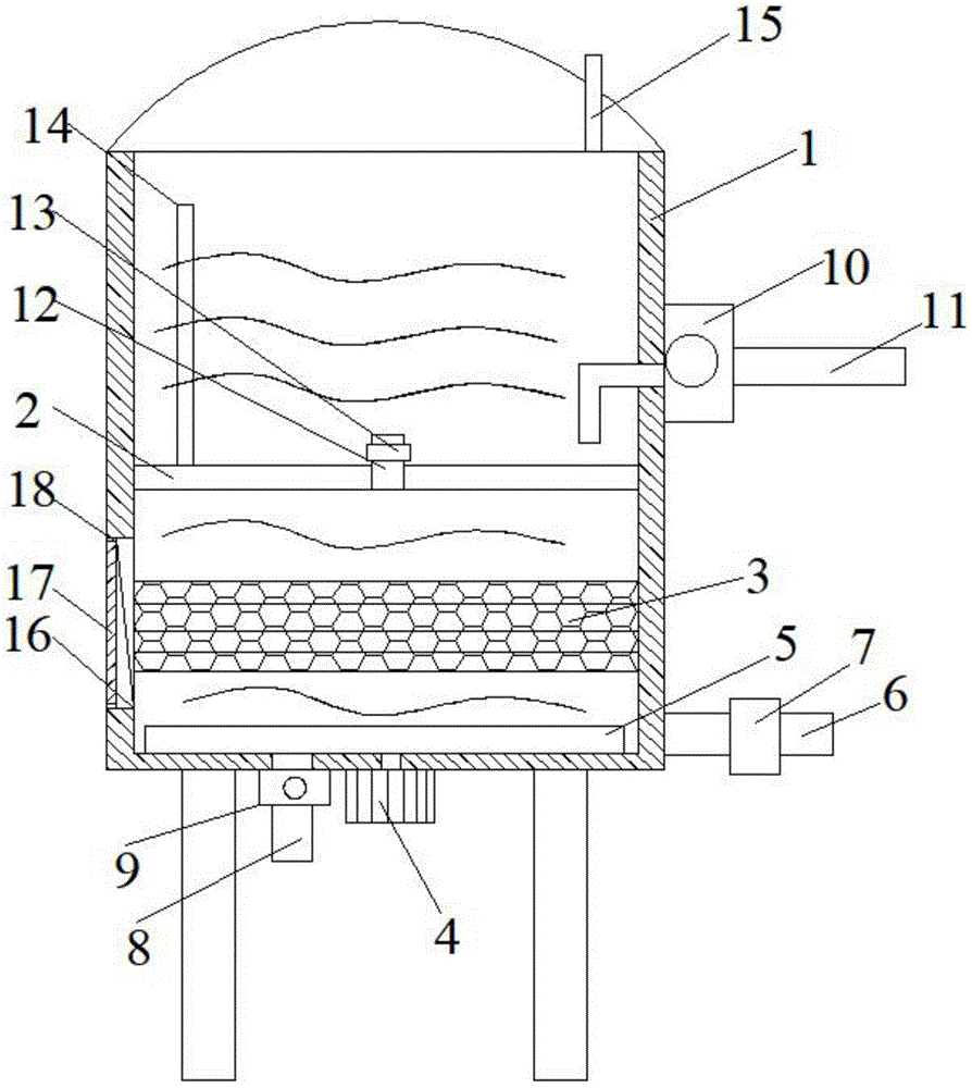
Fig. 1 is a schematic structural diagram of a high-efficiency water supply device according to an embodiment of the present invention.
Reference numerals:
1. a tank body; 2. a partition plate; 3. filtering the core plate; 4. a motor; 5. a squeegee; 6. a blow-off pipe; 7. a blowoff valve; 8. a water inlet pipe; 9. a water inlet pump; 10. draining pump; 11. a water delivery pipe; 12. a communicating pipe; 13. a one-way water valve; 14. a liquid level meter; 15. a one-way exhaust valve; 16. an access hole; 17. a sealing plate; 18. and (5) sealing rings.
Detailed Description
The invention will be further described with reference to the accompanying drawings and specific embodiments:
in the description of the present invention, it should be noted that the terms "top", "bottom", "one side", "the other side", "front", "back", "middle part", "inside", "top", "bottom", etc. indicate the orientation or positional relationship based on the orientation or positional relationship shown in the drawings, which is only for the convenience of description and simplification of the description, but does not indicate or imply that the device or element referred to must have a specific orientation, be constructed in a specific orientation, and be operated, and thus, should not be construed as limiting the present invention; the terms "first," "second," and "third" are used for descriptive purposes only and are not to be construed as indicating or implying relative importance; furthermore, unless expressly stated or limited otherwise, the terms "mounted," "connected," and "connected" are to be construed broadly, as they may be fixedly connected, detachably connected, or integrally connected, for example; can be mechanically or electrically connected; they may be connected directly or indirectly through intervening media, or they may be interconnected between two elements. The specific meaning of the above terms in the present invention can be understood in specific cases to those skilled in the art.
Referring to fig. 1, a high efficiency water supply apparatus according to an embodiment of the present invention includes a tank 1, a partition plate 2, a filter core plate 3, a motor 4, a scraper 5, a blow-off pipe 6, a blow-off valve 7, a water inlet pipe 8, a water inlet pump 9, a drain pump 10, a water pipe 11, a communication pipe 12, a one-way water valve 13, a level gauge 14 and a one-way exhaust valve 15, wherein the tank 1 is internally provided with the partition plate 2 to partition the tank 1 into an upper chamber and a lower chamber, the partition plate 2 is provided with the detachable filter core plate 3 below, the tank 1 is provided with an access hole 16 at one side of the filter core plate 3, the access hole 16 is provided with a sealing plate 17, the outer edge of the sealing plate 17 is provided with a sealing ring 18 sealed with the tank 1, the partition plate 2 is provided with the communication pipe 12 communicated with the upper chamber, the communication pipe 12 is provided with the one-way water valve 13, and one side of the tank 1 is provided with the drain pump 10, the input of drain pump 10 lets in the top that the pipeline let in baffle 2, motor 4 is installed to the bottom of the jar body 1, the drive of the output of motor 4 is connected and is located the indoor scraper blade 5 of lower part cavity, one side of the one end of the jar body 1 is equipped with the blow off pipe 6 rather than inside intercommunication, install blowoff valve 7 on the blow off pipe 6.
Through the above technical scheme of the utility model, the bottom of jar body 1 is equipped with the inlet tube 8 rather than the bottom inner chamber intercommunication, install intake pump 9 on the inlet tube 8.
Through the above technical scheme of the utility model, level gauge 14 is installed to the upper end of baffle 2.
Through the above technical scheme of the utility model, the one-way discharge valve 15 discharges that communicate rather than the upper portion cavity is installed at the top of jar body 1 and is mingled with the gas in water.
Through the above technical scheme of the utility model, water supply equipment still includes the controller, the controller receives the 14 liquid level signals of level gauge and carries out output control to drain pump 10 and avoids causing the phenomenon appearance that drain pump 10 air burns when upper portion cavity does not have the deposit water.
When specifically using, through intake pump 9 with water from inlet tube 8 suction to jar internal lower part cavity, water filters through filtering core 3, then filterable water enters into jar internal upper portion cavity from one-way water valve 13 and carries out interim storage, when dismantling closing plate 17 like this and take out filtering core 3 and clear up, drain pump 10 still can carry out the drainage supply from the upper portion cavity, when clearing up filtering core 3, drive scraper blade 5 through motor 4 and strike off bottom mud, open blowoff valve 7 and can discharge.
Finally, it should be noted that: although the present invention has been described in detail with reference to the foregoing embodiments, it will be apparent to those skilled in the art that modifications may be made to the embodiments described in the foregoing embodiments, or equivalents may be substituted for elements thereof. Any modification, equivalent replacement, or improvement made within the spirit and principle of the present invention should be included in the protection scope of the present invention.

Claims (5)

1. The high-efficiency water supply equipment is characterized by comprising a tank body (1), a partition plate (2), a filtering core plate (3), a motor (4), a scraper (5), a blow-off pipe (6), a blow-off valve (7), a water inlet pipe (8), a water inlet pump (9), a drainage pump (10), a water conveying pipe (11), a communication pipe (12), a one-way water valve (13), a liquid level meter (14) and a one-way exhaust valve (15), wherein the tank body (1) is internally provided with the partition plate (2) for separating the tank body (1) into an upper chamber and a lower chamber, the detachable filtering core plate (3) is arranged below the partition plate (2), one side of the tank body (1) positioned on the filtering core plate (3) is provided with an inspection hole (16), a sealing plate (17) is arranged at the inspection hole (16), and a sealing ring (18) sealed with the tank body (1) is arranged on the outer edge of the sealing plate (17), install communicating pipe (12) with upper portion cavity intercommunication on baffle (2), install one-way water valve (13) on communicating pipe (12), drain pump (10) are installed to one side of the jar body (1), the input of drain pump (10) lets in the top that the pipeline let in baffle (2), motor (4) are installed to the bottom of the jar body (1), the output drive of motor (4) is connected and is located scraper blade (5) of lower part cavity, one end one side of the jar body (1) is equipped with blow off pipe (6) rather than inside intercommunication, install blowoff valve (7) on blow off pipe (6).
2. A high efficiency water supply equipment according to claim 1 characterized in that the bottom of the tank (1) is provided with a water inlet pipe (8) communicated with the inner cavity of the bottom, and the water inlet pipe (8) is provided with a water inlet pump (9).
3. A high efficiency water supply apparatus as claimed in claim 1, wherein the upper end of the partition (2) is fitted with a liquid level gauge (14).
4. A high efficiency water supply apparatus as claimed in claim 1, wherein the top of the tank (1) is fitted with a one-way exhaust valve (15) communicating with its upper chamber.
5. A high efficiency water supply apparatus according to claim 1 further comprising a controller receiving a level signal from the level gauge (14) and controlling the output of the drain pump (10).
CN202122574075.9U 2021-10-26 2021-10-26 High efficiency water supply equipment Expired - Fee Related CN216428436U (en)

Priority Applications (1)

Application Number Priority Date Filing Date Title
CN202122574075.9U CN216428436U (en) 2021-10-26 2021-10-26 High efficiency water supply equipment

Applications Claiming Priority (1)

Application Number Priority Date Filing Date Title
CN202122574075.9U CN216428436U (en) 2021-10-26 2021-10-26 High efficiency water supply equipment

Publications (1)

Publication Number Publication Date
CN216428436U true CN216428436U (en) 2022-05-03

Family

ID=81333837

Family Applications (1)

Application Number Title Priority Date Filing Date
CN202122574075.9U Expired - Fee Related CN216428436U (en) 2021-10-26 2021-10-26 High efficiency water supply equipment

Country Status (1)

Country Link
CN (1) CN216428436U (en)

Similar Documents

Publication Publication Date Title
CN206934854U (en) A kind of efficient self-cleaning filter
CN210919470U (en) Self-suction type non-blocking sewage pump
CN217785954U (en) Plate heat exchanger belt cleaning device based on sound wave vibration and sulfamic acid
CN204610201U (en) A kind of Chalk-dust filtering impurity filtering tank
CN112607919A (en) Layered sewage treatment equipment
CN111120848A (en) A kind of commercial vehicle lubrication system cleaning and oil change equipment
CN207892848U (en) Self-suction pump pressure water chamber
CN216571807U (en) Self-cleaning bag filter
CN201189422Y (en) Centrifugal net-setting inner discharge type filtering device
CN211470879U (en) TMF sewage treatment system
CN211874743U (en) Connecting device of low-pressure air source type air stripping pump
CN214019505U (en) Stainless steel precise filtering device with backwashing structure
CN211946540U (en) Water pump separates sediment device
CN210993330U (en) Make things convenient for pipeline filter equipment of dismouting
CN219341764U (en) Pumping and filling device for diaphragm pressure gauge
CN211215745U (en) A new type of catalyst filter
CN210853745U (en) Vacuum automatic liquid discharge tank
CN222881394U (en) A vacuum gas hot water boiler
CN205980139U (en) Energy -efficient air supply arrangement
CN222009069U (en) A flat ceramic membrane water supply equipment
CN221630810U (en) Integrated structure of water meter and valve
CN217247635U (en) Negative pressure pipeline foreign matter filters clearing device
CN205980233U (en) Efficient air supply outlet
CN222565732U (en) Liner structure and dish washer
CN215232769U (en) Automatic exhaust device of water system

Legal Events

Date Code Title Description
GR01 Patent grant
GR01 Patent grant
CF01 Termination of patent right due to non-payment of annual fee

Granted publication date: 20220503

CF01 Termination of patent right due to non-payment of annual fee