CN216426174U - Cloth storage machine with tension mechanism - Google Patents
Cloth storage machine with tension mechanism Download PDFInfo
- Publication number
- CN216426174U CN216426174U CN202122999725.4U CN202122999725U CN216426174U CN 216426174 U CN216426174 U CN 216426174U CN 202122999725 U CN202122999725 U CN 202122999725U CN 216426174 U CN216426174 U CN 216426174U
- Authority
- CN
- China
- Prior art keywords
- cloth
- tension mechanism
- tension
- cloth storage
- storage machine
- Prior art date
- Legal status (The legal status is an assumption and is not a legal conclusion. Google has not performed a legal analysis and makes no representation as to the accuracy of the status listed.)
- Active
Links
- 239000004744 fabric Substances 0.000 title claims abstract description 82
- 230000007246 mechanism Effects 0.000 title claims abstract description 43
- 238000003860 storage Methods 0.000 title claims abstract description 43
- 230000005540 biological transmission Effects 0.000 claims abstract description 7
- 239000004745 nonwoven fabric Substances 0.000 abstract description 12
- 238000005096 rolling process Methods 0.000 abstract description 8
- 238000004804 winding Methods 0.000 description 5
- 230000008859 change Effects 0.000 description 2
- 238000010586 diagram Methods 0.000 description 2
- 238000007599 discharging Methods 0.000 description 2
- 238000000034 method Methods 0.000 description 2
- 230000008569 process Effects 0.000 description 2
- 230000009286 beneficial effect Effects 0.000 description 1
- 230000000694 effects Effects 0.000 description 1
- 238000004519 manufacturing process Methods 0.000 description 1
- 230000004048 modification Effects 0.000 description 1
- 238000012986 modification Methods 0.000 description 1
Images


Landscapes
- Treatment Of Fiber Materials (AREA)
Abstract
The utility model relates to a take tension mechanism's cloth storage machine, including storing up the cloth holder to and install fabric guide roll and the tension mechanism in storing up the cloth holder, tension mechanism sets up the play cloth side at the fabric guide roll, and tension mechanism includes drive assembly, and two with fabric guide roll parallel arrangement's tension roller, the both ends of tension roller are fixed on the end plate, the outside of end plate is provided with the pivot, drive assembly is connected with the pivot transmission of one side wherein. The utility model discloses can guarantee the tension of non-woven fabrics rolling when realizing storing up the cloth function to overall structure is simple, and it is convenient to adjust, has guaranteed the efficiency of rolling and the quality of lapping.
Description
Technical Field
The utility model belongs to the technical field of store up the cloth machine, concretely relates to take tension mechanism's cloth storage machine.
Background
In the non-woven fabric production industry, the rolls need to be changed after being fully rolled during rolling, the machine is not allowed to stop during roll changing, and the fabric storage machine is a main device for realizing the function. The existing cloth storage machine generally realizes the storage and release of non-woven fabrics during roll change by adjusting the distance between an upper row of cloth guide rollers and a lower row of cloth guide rollers. And this kind of store up cloth mode not only structure complicacy, need remove the operation to a whole row of fabric guide roller moreover at least, adjust inconveniently, the tension of non-woven fabrics can't obtain guaranteeing, influences rolling efficiency and lapping quality then.
SUMMERY OF THE UTILITY MODEL
The utility model aims at providing a take tension mechanism's cloth storage machine to solve it and adjust inconvenient problem.
The utility model discloses a take tension mechanism's cloth storage machine is realized like this:
a cloth storage machine with a tension mechanism comprises a cloth storage frame, a cloth guide roller and the tension mechanism, wherein the cloth guide roller and the tension mechanism are arranged in the cloth storage frame, the tension mechanism is arranged at the cloth outlet side of the cloth guide roller,
the tension mechanism comprises a driving assembly and two tension rollers arranged in parallel with the cloth guide roller, the two ends of each tension roller are fixed on the end plates, rotating shafts are arranged on the outer sides of the end plates, and the driving assembly is in transmission connection with the rotating shaft on one side.
Furthermore, the cloth guide rollers are arranged in an upper row and a lower row, and the two rows of cloth guide rollers are arranged in a staggered manner.
Furthermore, the two tension rollers are arranged in a central symmetry mode relative to the axis of the rotating shaft.
Furthermore, the drive assembly comprises a worm gear box connected with a rotating shaft on one side of the drive assembly, and a screw matched with the worm gear box.
Further, the worm wheel in the worm wheel and worm box is connected with the rotating shaft on the side where the worm wheel and worm box is located, and the worm is connected with the screw rod.
Furthermore, the tension mechanism further comprises two opposite wallboards which are arranged and fixed on the cloth storage rack, and the rotating shaft is installed on the wallboards through bearings.
Furthermore, the driving component is arranged on the outer side of one side wall plate and is in transmission connection with the rotating shaft on the side.
Furthermore, the screw rod is perpendicular to the tension roller, and the screw rod is fixed on the outer side of the side wall plate where the screw rod is located through a bearing seat.
Furthermore, a hand wheel is installed at the end of the screw rod.
After the technical scheme is adopted, the utility model discloses the beneficial effect who has does:
the utility model discloses a tension mechanism's setting can be when realizing storing up the cloth function, guarantees the tension of non-woven fabrics rolling to overall structure is simple, and it is convenient to adjust, has guaranteed the efficiency of rolling and the quality of lapping.
Drawings
The present invention will be further explained with reference to the drawings and examples.
Fig. 1 is a structural diagram of a cloth storage machine with a tension mechanism according to a preferred embodiment of the invention;
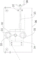
FIG. 2 is a front view of the tension mechanism of the cloth storage machine with the tension mechanism according to the preferred embodiment of the present invention;
FIG. 3 is an enlarged view of portion A of FIG. 2;
FIG. 4 is a structural diagram of the tension mechanism of the cloth storage machine with the tension mechanism in the cloth storage state according to the preferred embodiment of the present invention;
FIG. 5 is a structural view of the tension mechanism of the cloth storage machine with the tension mechanism in the releasing state according to the preferred embodiment of the present invention;
in the figure: store up cloth holder 1, fabric guide 2, tension mechanism 3, tension roller 31, end plate 32, pivot 33, worm gear case 34, screw rod 35, wallboard 36, bearing frame 37, hand wheel 38, slat 4.
Detailed Description
To make the objects, technical solutions and advantages of the embodiments of the present invention clearer, the drawings of the embodiments of the present invention are combined to clearly and completely describe the technical solutions of the embodiments of the present invention, and obviously, the described embodiments are some embodiments of the present invention, not all embodiments.
Thus, the following detailed description of the embodiments of the present invention, presented in the accompanying drawings, is not intended to limit the scope of the invention, as claimed, but is merely representative of selected embodiments of the invention. Based on the embodiments in the present invention, all other embodiments obtained by a person skilled in the art without creative work belong to the protection scope of the present invention.
As shown in fig. 1-5, a cloth storage machine with a tension mechanism comprises a cloth storage rack 1, and a cloth guide roller 2 and a tension mechanism 3 which are installed in the cloth storage rack 1, wherein the tension mechanism 3 is arranged at the cloth outlet side of the cloth guide roller 2, the tension mechanism 3 comprises a driving assembly and two tension rollers 31 which are arranged in parallel with the cloth guide roller 2, two ends of each tension roller 31 are fixed on an end plate 32, a rotating shaft 33 is arranged at the outer side of each end plate 32, and the driving assembly is in transmission connection with the rotating shaft 33 at one side.
In order to facilitate the conveying of the non-woven fabric, the cloth guide rollers 2 are arranged in an upper row and a lower row, and the two rows of cloth guide rollers 2 are arranged in a staggered manner.
Specifically, the cloth storage rack 1 is provided with opposite strips 4, and two ends of the cloth guide roller 2 are respectively mounted on the strips 4 through bearings.
The two tension rollers 31 are arranged in a central symmetry with respect to the axis of the rotating shaft 33.
Specifically, the end plate 32 is a waist-shaped plate, the two tension rollers 31 are fixed at both ends of the end plate 32, the rotating shaft 33 is fixed at the middle position of the end plate 32, and the two tension rollers 31 can rotate around the axis of the rotating shaft 33.
In the winding process, the tension roller 31 is in a cloth storage state, that is, the tension roller 31 positioned above is close to the cloth outlet side of the cloth storage machine, and correspondingly, the tension roller 31 positioned below is far away from the cloth outlet side of the cloth storage machine, so that the cloth storage length can be effectively ensured; during the change of the rolls, the tension roller 31 is switched to the release state, that is, the tension roller 31 located above rotates in the direction away from the cloth discharging side, and correspondingly, the tension roller 31 located below rotates in the direction toward the cloth discharging side of the cloth storage machine, so as to release the non-woven fabric.
In order to be able to drive the two tension rollers 31 to rotate, the driving assembly includes a worm gear box 34 connected to one side rotating shaft 33, and a screw 35 engaged with the worm gear box 34.
The worm wheel in the worm wheel and worm box 34 is connected with the rotating shaft 33 on the side where the worm wheel and worm box is located, and the worm is connected with the screw 35.
When the screw 35 is rotated, the worm rotates synchronously with the screw, and the worm wheel is matched with the worm wheel, so that the rotating shaft 33 can be driven to rotate through the worm wheel.
In order to fix the tension mechanism 3 conveniently, the tension mechanism 3 further includes two opposite wallboards 36 fixed on the cloth storage rack 1, and the rotating shaft 33 is mounted on the wallboards 36 through bearings.
In order to realize the matching of the driving assembly and the rotating shaft 33, the driving assembly is arranged on the outer side of one side wall plate 36 and is in transmission connection with the rotating shaft 33 on the side.
In order to reduce the width of the whole cloth storage machine, the screw 35 is perpendicular to the tension roller 31, and the screw 35 is fixed on the outer side of the side wall plate 36 through a bearing seat 37.
To facilitate rotation of the screw 35, a hand wheel 38 is mounted on the end of the screw 35.
In the process of winding the non-woven fabric, the non-woven fabric sequentially and alternately passes through the cloth guide rollers 2 from top to bottom, then bypasses from the upper part of the tension roller 31 positioned above, returns to bypass from the upper part of the tension roller 31 positioned below in a Z-shaped mode, and finally reaches the winding drum from the bottom of the tension roller 31, at the moment, the tension roller 31 is in a cloth storage state, when the belt needs to be wound, the screw rod 35 is rotated, the two tension rollers 31 are driven to rotate around the axis of the rotating shaft 33 through the worm gear box 34 and gradually rotate to a release state, the winding is realized without stopping, and the winding efficiency is improved. And the rotation angle and the rotation speed of the tension roller 31 can be adjusted at will according to the needs while rotating, so that the non-woven fabric is ensured to be in a tension state, and the coiling quality of the non-woven fabric is ensured.
The utility model has the advantages of simple overall structure, it is convenient to adjust, guarantees the tight effect that rises of non-woven fabrics rolling process when possessing the cloth storage function, improves rolling efficiency, guarantees the lapping quality.
In light of the foregoing, it will be apparent to those skilled in the art from this disclosure that various changes and modifications can be made without departing from the spirit and scope of the invention. The technical scope of the present invention is not limited to the content of the specification, and must be determined according to the scope of the claims.
Claims (9)
1. The cloth storage machine with the tension mechanism is characterized by comprising a cloth storage rack (1), a cloth guide roller (2) and a tension mechanism (3) which are arranged in the cloth storage rack (1), wherein the tension mechanism (3) is arranged on the cloth outlet side of the cloth guide roller (2),
tension mechanism (3) including drive assembly, and two with fabric guide roller (2) parallel arrangement's tension roller (31), the both ends of tension roller (31) are fixed on end plate (32), the outside of end plate (32) is provided with pivot (33), drive assembly is connected with pivot (33) transmission of one side wherein.
2. The cloth storage machine with the tension mechanism as claimed in claim 1, characterized in that the cloth guide rollers (2) are arranged in upper and lower rows, and the two rows of cloth guide rollers (2) are arranged in a staggered manner.
3. The cloth storage machine with tension mechanism as claimed in claim 1, characterized in that two tension rollers (31) are arranged in a central symmetry with respect to the axis of the rotating shaft (33).
4. The cloth storage machine with tension mechanism as claimed in claim 1, wherein the driving assembly comprises a worm gear box (34) connected to one side of the rotating shaft (33), and a screw (35) engaged with the worm gear box (34).
5. Cloth storage machine with tension mechanism according to claim 4, characterized in that the worm wheel in the worm wheel and worm box (34) is connected with the rotating shaft (33) on the side where it is located, and the worm is connected with the screw (35).
6. Cloth storage machine with tension mechanism according to claim 4, characterized in that the tension mechanism (3) further comprises two opposite wall plates (36) fixed on the cloth storage rack (1), and the rotating shaft (33) is mounted on the wall plates (36) through bearings.
7. The cloth storage machine with tension mechanism as claimed in claim 6, wherein the driving assembly is arranged outside one of the side wall plates (36) and is in transmission connection with the rotating shaft (33) on the side.
8. Cloth storage machine with tension mechanism according to claim 4, characterized in that the screw (35) is perpendicular to the tension roller (31) and the screw (35) is fixed outside the side wall plate (36) by a bearing block (37).
9. Cloth storage machine with tension mechanism according to claim 4, characterized in that the end of the screw (35) is fitted with a hand wheel (38).
Priority Applications (1)
| Application Number | Priority Date | Filing Date | Title |
|---|---|---|---|
| CN202122999725.4U CN216426174U (en) | 2021-12-01 | 2021-12-01 | Cloth storage machine with tension mechanism |
Applications Claiming Priority (1)
| Application Number | Priority Date | Filing Date | Title |
|---|---|---|---|
| CN202122999725.4U CN216426174U (en) | 2021-12-01 | 2021-12-01 | Cloth storage machine with tension mechanism |
Publications (1)
| Publication Number | Publication Date |
|---|---|
| CN216426174U true CN216426174U (en) | 2022-05-03 |
Family
ID=81341339
Family Applications (1)
| Application Number | Title | Priority Date | Filing Date |
|---|---|---|---|
| CN202122999725.4U Active CN216426174U (en) | 2021-12-01 | 2021-12-01 | Cloth storage machine with tension mechanism |
Country Status (1)
| Country | Link |
|---|---|
| CN (1) | CN216426174U (en) |
-
2021
- 2021-12-01 CN CN202122999725.4U patent/CN216426174U/en active Active
Similar Documents
| Publication | Publication Date | Title |
|---|---|---|
| CN211594457U (en) | An unwinding machine with edge correcting device for spinning | |
| CN202807973U (en) | Slitting machine | |
| CN103010806A (en) | Slitting machine | |
| CN216403256U (en) | Side cut waste collection device | |
| CN202697581U (en) | Automatic dough sheet winding device | |
| CN219597189U (en) | Regulation structure and coating machine conveying roller for spinning | |
| CN218024511U (en) | Weaving cloth coiling mechanism | |
| CN208856587U (en) | Winding device and half-folding cloth rolling machine | |
| CN206014001U (en) | A kind of embedded coiling device of water-jet loom | |
| CN218201379U (en) | Shredding device for processing polypropylene flexible freight bags | |
| CN216511825U (en) | Film storage rack | |
| CN211110146U (en) | A fabric winding device for flax textile processing | |
| CN211680293U (en) | Linear cutting device of aluminium strip | |
| CN211366434U (en) | A printing fabric rolling machine | |
| CN213294142U (en) | Winding device of film blowing machine | |
| CN212863389U (en) | Composite rolling device | |
| CN220787564U (en) | Automatic winding structure of cloth inspection machine | |
| CN220998710U (en) | Adjustable rewinding machine | |
| CN219341085U (en) | Grey cloth cutting machine | |
| CN215047266U (en) | Antistatic fabric winding device | |
| CN223372339U (en) | A cloth winding device | |
| CN213356367U (en) | Dual-purpose automatic opposite side cloth rewinder of needle shuttle | |
| CN218664517U (en) | Roll-up device capable of changing roll without stopping machine | |
| CN211848369U (en) | Cloth rolling device of single-side cloth splitting knitting machine | |
| CN218968332U (en) | Paper winder for paper product processing |
Legal Events
| Date | Code | Title | Description |
|---|---|---|---|
| GR01 | Patent grant | ||
| GR01 | Patent grant |