CN216411035U - Building engineering facing brick bonding strength detects appurtenance - Google Patents
Building engineering facing brick bonding strength detects appurtenance Download PDFInfo
- Publication number
- CN216411035U CN216411035U CN202122937259.7U CN202122937259U CN216411035U CN 216411035 U CN216411035 U CN 216411035U CN 202122937259 U CN202122937259 U CN 202122937259U CN 216411035 U CN216411035 U CN 216411035U
- Authority
- CN
- China
- Prior art keywords
- telescopic rod
- bonding strength
- detecting
- auxiliary tool
- supporting frame
- Prior art date
- Legal status (The legal status is an assumption and is not a legal conclusion. Google has not performed a legal analysis and makes no representation as to the accuracy of the status listed.)
- Active
Links
- 239000011449 brick Substances 0.000 title claims abstract description 34
- 238000001179 sorption measurement Methods 0.000 claims abstract description 9
- 238000010521 absorption reaction Methods 0.000 claims 1
- 239000011468 face brick Substances 0.000 claims 1
- 238000001514 detection method Methods 0.000 abstract description 27
- 239000002184 metal Substances 0.000 abstract description 22
- 239000002390 adhesive tape Substances 0.000 description 9
- 238000000034 method Methods 0.000 description 6
- 230000000694 effects Effects 0.000 description 5
- 230000007547 defect Effects 0.000 description 4
- 238000010276 construction Methods 0.000 description 3
- 230000009286 beneficial effect Effects 0.000 description 2
- 238000012986 modification Methods 0.000 description 2
- 230000004048 modification Effects 0.000 description 2
- 241000252254 Catostomidae Species 0.000 description 1
- 239000000853 adhesive Substances 0.000 description 1
- 230000001070 adhesive effect Effects 0.000 description 1
- 238000004140 cleaning Methods 0.000 description 1
- 238000005336 cracking Methods 0.000 description 1
- 238000005516 engineering process Methods 0.000 description 1
- 238000012423 maintenance Methods 0.000 description 1
- 239000002994 raw material Substances 0.000 description 1
- 238000006467 substitution reaction Methods 0.000 description 1
- 239000002352 surface water Substances 0.000 description 1
- 238000001931 thermography Methods 0.000 description 1
Images

Landscapes
- Hooks, Suction Cups, And Attachment By Adhesive Means (AREA)
Abstract
The utility model relates to an auxiliary tool for detecting the bonding strength of a facing brick in building engineering, belonging to the field of auxiliary tools for detection, and comprising a supporting frame, a clamping assembly and an adsorption assembly; the supporting frame is of a hollow structure, the clamping assembly comprises a first telescopic rod, one end of the first telescopic rod is connected with the inner surface of the supporting frame, and the other end of the first telescopic rod is connected with the push plate; the adsorption assembly comprises a linear guide rail, a moving block is matched with the inside of the linear guide rail, a pushing block is arranged on the moving block, a groove is formed in the pushing block, and a second telescopic rod is arranged in the groove. The metal block matched with the detection instrument can be attached to the facing brick, the metal block is not required to be pressed by a hand of the detection instrument, and the metal block can be better fixed on a required detection part; and utilize the sucking disc to adsorb facing brick or other objects for the metal block can be fixed in the position that needs the detection fast, moreover can reuse, has improved bonding efficiency.
Description
Technical Field
The utility model relates to the technical field of detection auxiliary tools, in particular to an auxiliary tool for detecting the bonding strength of a facing brick in constructional engineering.
Background
The facing bricks are used in a large amount in the building outer wall with the advantages of attractive appearance, economy, easy cleaning and maintenance and the like, but the facing bricks of the outer wall are exposed outdoors for a long time and are influenced by factors such as construction process, weather conditions, raw materials, building design and the like, and quality problems such as hollowing, debonding, cracking, wall surface water seepage and the like easily occur, so that the quality of the facing bricks is detected and controlled, the personal safety can be prevented from being endangered by falling from high altitude, and the integral attractiveness of the building is also concerned. Taking a certain building as an example, the defects of the facing bricks of the external wall of the building are detected and identified by using a traditional detection method, such as a hollowing knocking method, an appearance detection method and an infrared thermography method, and the reasons of hollowing or other defects in the interior of the facing bricks are analyzed by detecting the bonding strength of the facing bricks.
However, in the detection process of the prior art, the detector is often used in cooperation with a metal block, the metal block has a certain weight, the metal block is not adhered to form a broken seam when being adhered, and the metal block is fixed by using an adhesive tape in time, but the fixing mode has low working efficiency, the fixing time is too long, and the working efficiency of detection personnel is seriously influenced. However, in actual detection, because the standard block is adhered to the side face of the facing brick wall, the adhesive needs at least 6-10 minutes for fixing, and is generally pressed by hands of an inspector and is difficult to fix by using a common adhesive tape. And the adhesive tape is used for fixing, the adhesive tape cannot be used repeatedly, resources are wasted, the environment is polluted, and the common adhesive tape is used for fixing, so that the working efficiency is inevitably too low, and the fixing effect is poor.
SUMMERY OF THE UTILITY MODEL
The utility model overcomes the defects of the prior art and provides an auxiliary tool for detecting the bonding strength of the facing bricks in the building engineering.
In order to achieve the purpose, the utility model adopts the technical scheme that:
the utility model relates to an auxiliary tool for detecting the bonding strength of a facing brick in building engineering, which comprises a supporting frame, a clamping component and an adsorption component, wherein the clamping component is arranged on the supporting frame;
the supporting frame is of a hollow structure, the clamping assembly comprises a first telescopic rod, one end of the first telescopic rod is connected with the inner surface of the supporting frame, and the other end of the first telescopic rod is connected with the push plate;
the adsorption assembly comprises a linear guide rail, a moving block is matched with the inside of the linear guide rail, a pushing block is arranged on the moving block, a groove is formed in the pushing block, and a second telescopic rod is arranged in the groove.
Further, in a preferred embodiment of the present invention, the second telescopic rod is provided with a through hole, and the through hole is matched with the support rod.
Further, in a preferred embodiment of the present invention, the second telescopic rod is further provided with a first threaded hole.
Further, in a preferred embodiment of the present invention, one end of the supporting rod is connected to a suction cup fixing block, and the suction cup fixing block is provided with a plurality of second threaded holes.
Further, in a preferred embodiment of the present invention, the second threaded holes are capable of connecting with suction cups.
Further, in a preferred embodiment of the present invention, the linear guide rails are all disposed around the supporting frame.
Further, in a preferred embodiment of the present invention, the support rod is freely adjustable in position through the first threaded hole.
Further, in a preferred embodiment of the present invention, the first telescopic rod is sleeved with a spring.
Further, in a preferred embodiment of the present invention, the suction cup is made of rubber, PVC or TPE.
Further, in a preferred embodiment of the present invention, the suction cup forms at least a suction area of 8-12 cm.
The utility model solves the defects in the background technology, and has the following beneficial effects:
the metal block matched with the detection instrument can be attached to the facing brick, the metal block does not need to be pressed by a hand of the detection instrument, the metal block can be better fixed at a required detection part, and the technical problem that a common adhesive tape is difficult to adhere to the facing brick can be solved; on the other hand, the technical problems that the adhesive tape cannot be used repeatedly, resources are wasted and the environment is polluted are solved; on the other hand, utilize the sucking disc to adsorb facing brick or other objects for the metal block can be fixed in the position that needs the detection fast, moreover can reuse, has improved bonding efficiency.
Drawings
The accompanying drawings, which are incorporated in and constitute a part of this specification, are included to provide a further understanding of the utility model, and are incorporated in and constitute a part of this specification, illustrate exemplary embodiments of the utility model and together with the description serve to explain the utility model and not to limit the utility model.
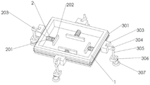
FIG. 1 is a schematic perspective view of an auxiliary tool for detecting bonding strength of a facing brick in construction engineering;
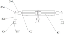
FIG. 2 is a schematic side view of an auxiliary tool for detecting the bonding strength of the facing brick in the construction engineering;
fig. 3 is a schematic top view of an auxiliary tool for detecting the bonding strength of the facing brick in the building engineering.
In the figure:
1. the vacuum suction cup comprises a supporting frame, 2 parts of a clamping assembly, 3 parts of an adsorption assembly, 201 parts of a first telescopic rod, 202 parts of a push plate, 203 parts of a spring, 301 parts of a linear guide rail, 302 parts of a moving block, 303 parts of a pushing block, 304 parts of a second telescopic rod, 305 parts of a supporting rod, 306 parts of a suction cup fixing block, 307 parts of a suction cup.
Detailed Description
The technical solutions in the embodiments of the present invention will be clearly and completely described below with reference to the drawings in the embodiments of the present invention, and it is obvious that the described embodiments are only a part of the embodiments of the present invention, and not all of the embodiments. All other embodiments, which can be derived by a person skilled in the art from the embodiments given herein without making any creative effort, shall fall within the protection scope of the present invention.
Reference in the specification to "an embodiment," "one embodiment," "some embodiments," or "other embodiments" means that a particular feature, structure, or characteristic described in connection with the embodiments is included in at least some embodiments, but not necessarily all embodiments. The various appearances of "an embodiment," "one embodiment," or "some embodiments" are not necessarily all referring to the same embodiments. If the specification states a component, feature, structure, or characteristic "may", "might", or "could" be included, that particular component, feature, structure, or characteristic is not required to be included. If the specification or claim refers to "a" or "an" element, that does not mean there is only one of the element. If the specification or claim refers to "a further" element, that does not preclude there being more than one of the further element. Furthermore, the particular features, structures, functions, or characteristics may be combined in any suitable manner in one or more embodiments. For example, a first embodiment may be combined with a second embodiment as long as the particular features, structures, functions, or characteristics associated with the two embodiments are not mutually exclusive.
In the description of the present invention, unless otherwise specified the use of the ordinal adjectives "first", "second", and "third", etc., to describe a common object, merely indicate that different instances of like objects are being referred to, and are not intended to imply that the objects so described must be in a given sequence, either temporally, spatially, in ranking, or in any other manner. In the description of the utility model, the meaning of "a plurality" is two or more unless otherwise specified.
In the description of the present invention, it should be noted that, unless otherwise explicitly specified or limited, the terms "mounted," "connected," and "connected" are to be construed broadly, e.g., as meaning either a fixed connection, a removable connection, or an integral connection; can be mechanically or electrically connected; they may be connected directly or indirectly through intervening media, or they may be interconnected between two elements. The specific meaning of the above terms in the present invention can be understood by those of ordinary skill in the art through specific situations.
The utility model relates to an auxiliary tool for detecting the bonding strength of a facing brick in building engineering, which comprises a supporting frame 1, a clamping component 2 and an adsorption component 3;
the supporting frame 1 is a hollow structure, the clamping assembly 2 comprises a first telescopic rod 201, one end of the first telescopic rod 201 is connected with the inner surface of the supporting frame 1, and the other end of the first telescopic rod 201 is connected with a push plate 202;
it should be noted that, utilize the flexible ability of first telescopic link 201 to make push pedal 202 promote the side with the metal block that detecting instrument cooperation was used under the effect of spring force for the metal block can in time be fixed, and then utilize sucking disc 307 to adsorb on the wall body, make the position that detection personnel can detect as required detect the bonding strength of facing brick, this process all can be fixed in the middle of the position that needs detected with the metal block fast, has improved work efficiency.
The adsorption component 3 comprises a linear guide rail 301, a moving block 302 is matched inside the linear guide rail 301, a pushing block 303 is arranged on the moving block 302, a groove is formed in the pushing block 303, and a second telescopic rod 304 is arranged in the groove.
It should be noted that the moving block 302 can move in the linear guide 301, when the detector is in use, especially at some corner positions, the additional suction cup 307 can move in the horizontal linear direction, so as to meet more working requirements, and the detector can adjust the position of the suction cup 307 in the horizontal direction, so that convenience is provided for the detector, and the practicability is higher.
Further, in a preferred embodiment of the present invention, the second telescopic rod 304 is provided with a through hole, and the through hole is engaged with the supporting rod 305.
It should be noted that, as shown in fig. 3, the second telescopic rod 304 is arranged, so that the second telescopic rod 304 can move left and right, the work requirement of more detection personnel is met, when the second telescopic rod is not used, the second telescopic rod can be accommodated in the groove of the pushing block 303, so that the use space is smaller, the occupied size is small, and the carrying convenience of the detection personnel is facilitated.
Further, in a preferred embodiment of the present invention, the second telescopic rod 304 is further provided with a first threaded hole.
It should be noted that, as shown in fig. 2, a first threaded hole is provided on the second telescopic rod 304, and when in use, an inspector can screw into the first threaded hole with a common screw rod, so as to fix the supporting rod 305; when needing to be adjusted, the position of the adjusting support bar 305 is locked by a common screw rod, which is beneficial to measuring some uneven detection positions, flexibly adjusting the position of the sucking disc 307, and having stronger practicability.
Further, in a preferred embodiment of the present invention, a suction cup fixing block 306 is connected to one end of the supporting rod 305, and a plurality of second threaded holes are formed in the suction cup fixing block 306.
Further, in a preferred embodiment of the present invention, the second threaded holes are capable of being connected with the suction cups 307.
It should be noted that, by providing a plurality of second threaded holes on the suction cup fixing block 306, the number of the suction cups 307 or the positions of the suction cups 307 can be adjusted by the inspector according to the actual working requirement, so that the metal block can have a better fixing effect,
further, in a preferred embodiment of the present invention, the linear guide rails 301 are all disposed around the supporting frame 1.
It should be noted that, a plurality of suckers 307 are arranged around the supporting frame 1, so that the fixed positions of the detection personnel are selected more in the detection process, the detection personnel can fix the metal blocks according to the actual working requirements, and the fixing mode is selected more, so that the fixing effect is better, and the fixing efficiency is better.
Further, in a preferred embodiment of the present invention, the supporting rod 305 is freely adjustable in position through the first threaded hole.
Further, in a preferred embodiment of the present invention, the first telescopic rod 201 is sleeved with a spring 203.
It should be noted that the pushing force is applied to the pushing plate 202 by the elastic force of the spring 203, so that the tool can adapt to metal blocks with different sizes, meet more use requirements of detection personnel, and have more selectable modes.
Further, in a preferred embodiment of the present invention, the suction cup 307 is made of rubber, PVC or TPE.
Further, in a preferred embodiment of the present invention, the suction cup 307 at least forms a suction area of 8-12 cm.
It should be noted that the suction cup 307 is made of rubber, PVC or TPE, so that when the suction cup 307 is fixed to a specific position, the suction cup can be attached to a wall surface or a facing tile, and the larger the fixing area is, the better the fixing effect is.
In conclusion, the metal block matched with the detection instrument for use can be attached to the facing brick, the metal block does not need to be pressed by a hand of the detection instrument, the metal block can be better fixed at a required detection part, and the technical problem that the common adhesive tape is difficult to adhere to the facing brick can be solved; on the other hand, the technical problems that the adhesive tape cannot be used repeatedly, resources are wasted and the environment is polluted are solved; on the other hand, utilize the sucking disc to adsorb facing brick or other objects for the metal block can be fixed in the position that needs the detection fast, moreover can reuse, has improved bonding efficiency.
Finally, the above embodiments are only intended to illustrate the technical solutions of the present invention and not to limit the present invention, and although the present invention has been described in detail with reference to the preferred embodiments, it will be understood by those skilled in the art that modifications or equivalent substitutions may be made on the technical solutions of the present invention without departing from the spirit and scope of the technical solutions, and all of them should be covered by the claims of the present invention.
Although the embodiments of the present invention have been described with reference to the accompanying drawings, it is not intended to limit the scope of the present invention, and it should be understood by those skilled in the art that various modifications and variations can be made without inventive efforts by those skilled in the art based on the technical solution of the present invention.
Claims (10)
1. An auxiliary tool for detecting the bonding strength of a facing brick in building engineering is characterized by comprising a supporting frame, a clamping assembly and an adsorption assembly;
the supporting frame is of a hollow structure, the clamping assembly comprises a first telescopic rod, one end of the first telescopic rod is connected with the inner surface of the supporting frame, and the other end of the first telescopic rod is connected with the push plate;
the adsorption assembly comprises a linear guide rail, a moving block is matched with the inside of the linear guide rail, a pushing block is arranged on the moving block, a groove is formed in the pushing block, and a second telescopic rod is arranged in the groove.
2. The auxiliary tool for detecting the bonding strength of the facing bricks in the building engineering as claimed in claim 1, wherein the second telescopic rod is provided with a through hole, and a support rod is fitted in the through hole.
3. The auxiliary tool for detecting the bonding strength of the facing bricks in the building engineering as claimed in claim 2, wherein the second telescopic rod is further provided with a first threaded hole.
4. The auxiliary tool for detecting the bonding strength of the facing bricks in the building engineering as claimed in claim 2, wherein a suction cup fixing block is connected to one end of the supporting rod, and a plurality of second threaded holes are formed in the suction cup fixing block.
5. The auxiliary tool for detecting the bonding strength of the architectural engineering facing bricks according to claim 4, wherein the second threaded holes are connected with suction cups.
6. The auxiliary tool for detecting the bonding strength of the architectural engineering facing bricks according to claim 1, wherein the linear guide rails are all arranged around the supporting frame.
7. The auxiliary tool for detecting the bonding strength of the architectural engineering facing bricks according to claim 2, wherein the supporting rod is freely adjusted in position through the first threaded hole.
8. The auxiliary tool for detecting the bonding strength of the facing bricks in the building engineering as claimed in claim 1, wherein the first telescopic rod is sleeved with a spring.
9. The tool as claimed in claim 5, wherein the suction cup is made of rubber, PVC or TPE.
10. The auxiliary tool for testing the bonding strength of the architectural engineering face bricks according to claim 5, wherein the suction cup at least forms an absorption area of 8-12 square centimeters.
Priority Applications (1)
| Application Number | Priority Date | Filing Date | Title |
|---|---|---|---|
| CN202122937259.7U CN216411035U (en) | 2021-11-26 | 2021-11-26 | Building engineering facing brick bonding strength detects appurtenance |
Applications Claiming Priority (1)
| Application Number | Priority Date | Filing Date | Title |
|---|---|---|---|
| CN202122937259.7U CN216411035U (en) | 2021-11-26 | 2021-11-26 | Building engineering facing brick bonding strength detects appurtenance |
Publications (1)
| Publication Number | Publication Date |
|---|---|
| CN216411035U true CN216411035U (en) | 2022-04-29 |
Family
ID=81303749
Family Applications (1)
| Application Number | Title | Priority Date | Filing Date |
|---|---|---|---|
| CN202122937259.7U Active CN216411035U (en) | 2021-11-26 | 2021-11-26 | Building engineering facing brick bonding strength detects appurtenance |
Country Status (1)
| Country | Link |
|---|---|
| CN (1) | CN216411035U (en) |
-
2021
- 2021-11-26 CN CN202122937259.7U patent/CN216411035U/en active Active
Similar Documents
| Publication | Publication Date | Title |
|---|---|---|
| CN211369185U (en) | Direct hanging type stone decoration curtain wall | |
| CN111677155B (en) | Building curtain wall mechanism | |
| CN107740520B (en) | High strength curtain bearing structure for building | |
| CN217901836U (en) | High insulation resistance tester of stability | |
| CN211206208U (en) | Building is managed with facing brick bonding strength field inspection device | |
| CN110905078A (en) | A prefabricated movable building based on steel structure | |
| CN219386897U (en) | Positioning tool based on profiled steel sheet installation | |
| CN210347018U (en) | Building curtain wall air tightness detection device capable of adjusting positions in multiple directions | |
| CN209941994U (en) | Building curtain wall structure that can splice | |
| CN215173972U (en) | Architectural decoration detects structure | |
| CN216405858U (en) | Supporting structure for curtain wall installation | |
| CN214894624U (en) | Glass curtain wall hardness detection device | |
| CN113624196B (en) | High-rise outer wall overhanging scaffold deformation detection device | |
| CN205630411U (en) | Tight connecting device of special clamp of profiled sheet location frock | |
| CN219006602U (en) | Clamping assembly for glass processing | |
| CN210122778U (en) | Curtain wall structure for building | |
| CN223753655U (en) | Positioning construction frame for attaching building engineering wall | |
| CN205630410U (en) | Special closing device of profiled sheet location frock | |
| CN216865752U (en) | A solar glazed tile | |
| CN221323939U (en) | Environment detector with convenient installation | |
| CN217384624U (en) | House antidetonation detection device | |
| CN112575937A (en) | Glass curtain wall with 5G signal module | |
| CN221404179U (en) | Flatness detection device for inner wall and outer wall of house | |
| CN220339867U (en) | Building material hardness detection device | |
| CN212078421U (en) | Protector for indoor building decoration |
Legal Events
| Date | Code | Title | Description |
|---|---|---|---|
| GR01 | Patent grant | ||
| GR01 | Patent grant |