Hollow brick brickmaking machine of adjustable brickmaking thickness
Technical Field
The utility model relates to the technical field of hollow brick making machines, in particular to a hollow brick making machine capable of adjusting brick making thickness.
Background
As the name implies, brick making machines are mechanical equipment for producing bricks, and generally utilize stone powder, fly ash, slag, broken stone, sand, water and the like as raw materials. The fly ash, the slag, the mountain flour, the desulfurized fly ash, the slag, the coal gangue, the phosphogypsum, the tailing sand and the like are efficiently utilized to produce novel wall materials, such as autoclaved fly ash bricks, autoclaved sand-lime bricks, aerated concrete products and the like.
The search application number CN201820013099.2 discloses a hollow brick press forming machine, which comprises a hollow cavity, a lower cover plate, an upper cover plate and a left pressure plate, wherein the hollow cavity is formed by welding a right fixing plate and two side fixing plates, the lower cover plate is connected with a first hydraulic oil cylinder through a first piston rod, the upper cover plate is connected with a second hydraulic oil cylinder through a second piston rod, the left side of the left pressure plate is connected with the air cylinder through a connecting rod, the lower cover plate and the upper cover plate can be inserted between the fixing plates at the two sides, the width and the height of the left pressing plate are consistent with those of the right fixing plate, the inner sides of the lower cover plate and the upper cover plate are provided with a first metal rod, a second metal rod is arranged on the right side of the left pressing plate, a feed inlet is arranged at the left end of the upper cover plate, a through hole matched with the second metal rod is arranged in the center of the right fixing plate, the second metal rod is a cylindrical rod, and the end face of the outer end of the first metal rod is matched with the cylindrical surface of the second metal rod.
However, the inventor finds that the technical scheme still has at least the following defects:
the thickness of hollow brick suppression can not be controlled in its pressing process, also can not the automatic drawing of patterns, makes fragment of brick production efficiency variation, and the material causes the liquid level to distribute unevenly when getting into the mould inside simultaneously, and the atress is uneven in the pressing process, leads to the fragment of brick quality variation easily.
Therefore, the hollow brick making machine capable of adjusting the brick making thickness is provided.
SUMMERY OF THE UTILITY MODEL
The utility model mainly solves the technical problems in the prior art and provides the hollow brick making machine capable of adjusting the brick making thickness.
In order to achieve the purpose, the utility model adopts the following technical scheme that the hollow brick making machine capable of adjusting the brick making thickness comprises a frame, a slide rod fixedly arranged on the front end surface of the frame, a first air cylinder fixedly arranged on the front end of the top end surface of the frame, a second air cylinder fixedly arranged on the rear end of the top end surface of the frame and a brick mold fixedly arranged on the front end surface of the frame, the output end of the first cylinder penetrates through the top end face of the frame and extends to the front end face of the frame, an upper supporting plate is fixedly arranged on the output end of the first cylinder, lower supporting plates are sleeved on the outer wall faces of the two groups of sliding rods corresponding to the lower ends of the brick molds, the left end and the right end of the lower supporting plate are fixedly provided with linkage blocks in a mirror image manner, the left end surface and the right end surface of the upper supporting plate are movably provided with linkage rods capable of swinging back and forth corresponding to the positions of the linkage blocks, the output end of the second cylinder is fixedly provided with a brick pushing plate, and the positions of the two groups of sliding rods, which are close to the brick mold, are fixedly provided with a vibration shell.
Preferably, the upper supporting plate is sleeved between the two groups of sliding rods, a brick upper pressing plate is fixedly mounted on the bottom end face of the upper supporting plate, and the brick upper pressing plate is a block matched with a brick mold.
Preferably, the top end face of the lower supporting plate is fixedly provided with a stripper plate, the stripper plate is of a structure that the upper end is a rectangular plate and the lower end is a rectangular strip, and the rectangular strip of the stripper plate penetrates through the rectangular plate of the bottom end face stripper plate of the brick mold and is movably arranged inside the brick mold.
Preferably, the top end face of the linkage block is a block with the same horizontal height as that of the top end face of the stripper plate, a linkage groove is formed in the front end face of the linkage block, the linkage rod is of a hook-shaped structure at the bottom end, the bottom end face of the linkage rod is obliquely arranged, the linkage rod can move up and down in the linkage groove, push rods are fixedly mounted at the left end and the right end of the brick pushing plate in a mirror image mode, and one end, far away from the brick pushing plate, of each push rod is bent towards the linkage rod corresponding to the position of the linkage rod.
Preferably, the end face of the vibration shell close to the brick mold is provided with a vibration groove, a vibration block is movably mounted inside the vibration groove, a spring is fixedly mounted between the end faces of the vibration block and the vibration groove far away from the brick mold, and the end face of the vibration block far away from the brick mold penetrates through the vibration shell and is fixedly mounted with a support plate.
Preferably, a brick shaft groove is formed in the end face, close to the rack, of the vibration shell, a brick shaft capable of rotating bricks around the axis of the brick shaft groove is movably mounted between the brick shaft groove and the rack, a protruding block is fixedly mounted on the outer wall face of the brick shaft corresponding to the position of the abutting plate, and a gear is fixedly mounted on the outer wall face of the brick shaft.
Preferably, a rack is fixedly installed on the bottom end face of the upper supporting plate corresponding to the gear, a toothed structure is arranged on the end face of the rack close to the gear, and the rack is in meshed connection with the gear.
Advantageous effects
The utility model provides a hollow brick making machine capable of adjusting brick making thickness. The method has the following beneficial effects:
(1) the hollow brick making machine capable of adjusting the brick making thickness is characterized in that after materials are placed into a brick mold, a first air cylinder is started, the first air cylinder drives an upper supporting plate to move downwards, a real-time brick upper pressing plate presses the materials in the brick mold into bricks, a linkage rod moves downwards to enter a linkage groove, after pressing is completed, the first air cylinder is started, the first air cylinder drives the upper supporting plate to move upwards, so that the brick upper pressing plate is separated from the interior of the brick mold, the linkage rod drives a linkage block to move upwards, the linkage block drives a lower supporting plate to move upwards, the lower supporting movable demolding plate separates pressed bricks from the interior of the brick mold in the brick mold, then a second air cylinder is started, a brick pushing plate moves forwards to push the bricks away from the top end face of the demolding plate, meanwhile, a push rod pushes the linkage rod to separate the linkage rod from the linkage groove, so that the linkage plate slides downwards, the lower supporting plate is reset, and the effect of pressing bricks with different thicknesses is realized by putting different amounts of raw materials and controlling the pressing distance of the first cylinder.
(2) This hollow brick brickmaking machine of adjustable brickmaking thickness, when the backup pad downstream, drive rack downstream, the rack makes the brick axle brick move through the gear, the in-process that brick axle drive protruding block brick moved will support the board to the direction extrusion of keeping away from the fragment of brick mould, make the spring produce deformation, when the lug removed outside supporting the board, spring drive shakes the piece and strikes to the fragment of brick mould, make the material in the fragment of brick mould produce the vibration, make the material more balanced, thereby make the material at the in-process of pressing the brick, the atress is even, improve the suppression quality of fragment of brick.
Drawings
In order to more clearly illustrate the embodiments of the present invention or the technical solutions in the prior art, the drawings used in the description of the embodiments or the prior art will be briefly described below. It should be apparent that the drawings in the following description are merely exemplary, and that other embodiments can be derived from the drawings provided by those of ordinary skill in the art without inventive effort.
The structures, ratios, sizes, and the like shown in the present specification are only used for matching with the contents disclosed in the specification, so as to be understood and read by those skilled in the art, and are not used to limit the conditions that the present invention can be implemented, so that the present invention has no technical significance, and any structural modifications, changes in the ratio relationship, or adjustments of the sizes, without affecting the effects and the achievable by the present invention, should still fall within the range that the technical contents disclosed in the present invention can cover.
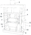
FIG. 1 is a schematic perspective view of the present invention;
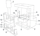
FIG. 2 is an exploded perspective view of the present invention;
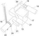
FIG. 3 is an exploded view of the vibrating structure of the present invention.
Illustration of the drawings:
1. a frame; 2. a slide rod; 3. a first cylinder; 4. a second cylinder; 5. a brick mold; 6. an upper support plate; 7. a brick upper pressing plate; 8. a lower support plate; 9. a stripper plate; 10. a linkage block; 11. a linkage groove; 12. a linkage rod; 13. pushing a brick plate; 14. a push rod; 15. vibrating the shell; 16. a rack; 17. a vibration groove; 18. a vibration block; 19. a spring; 20. a resisting plate; 21. brick shaft grooves; 22. a brick shaft; 23. a bump; 24. a gear.
Detailed Description
The technical solutions in the embodiments of the present invention will be clearly and completely described below with reference to the drawings in the embodiments of the present invention, and it is obvious that the described embodiments are only a part of the embodiments of the present invention, and not all of the embodiments. All other embodiments, which can be derived by a person skilled in the art from the embodiments given herein without making any creative effort, shall fall within the protection scope of the present invention.
Example (b): a hollow brick making machine capable of adjusting brick making thickness comprises a frame 1, a sliding rod 2 fixedly arranged on the front end face of the frame 1, a first air cylinder 3 fixedly arranged on the front end of the top end face of the frame 1, a second air cylinder 4 fixedly arranged on the rear end of the top end face of the frame 1 and a brick mold 5 fixedly arranged on the front end face of the frame 1, wherein the output end of the first air cylinder 3 penetrates through the top end face of the frame 1, extends to the front end face of the frame 1 and is fixedly provided with an upper supporting plate 6, the upper supporting plate 6 is a rectangular plate, the upper supporting plate 6 is sleeved between the two groups of sliding rods 2, the bottom end face of the upper supporting plate 6 is fixedly provided with a brick upper pressing plate 7, the brick upper pressing plate 7 is a block matched with the brick mold 5, the upper pressing plate 7 can move up and down in the brick mold 5, the brick upper pressing plate 7 is matched with the brick mold 5 to press materials in the brick mold 5 into bricks, the outer wall surfaces of the two groups of slide rods 2 are sleeved with a lower supporting plate 8 corresponding to the lower end of a brick mold 5, the lower supporting plate 8 is a rectangular plate, a stripper plate 9 is fixedly arranged on the top end surface of the lower supporting plate 8, the stripper plate 9 is of a structure that the upper end is a rectangular plate and the lower end is a rectangular strip, the rectangular strip of the stripper plate 9 penetrates through the rectangular plate of the bottom end surface stripper plate 9 of the brick mold 5 and is movably arranged in the brick mold 5, linkage blocks 10 are fixedly arranged on the left end and the right end of the lower supporting plate 8 in a mirror image manner, the top end surface of each linkage block 10 is a rectangular plate with the horizontal height identical to that of the top end surface of the stripper plate 9, a linkage groove 11 is formed in the front end surface of each linkage block 10, each linkage groove 11 is a rectangular groove, linkage rods 12 capable of swinging back and forth are movably arranged at the positions, corresponding to the linkage grooves 11, the bottom ends of the upper supporting plate 6 are of hook-shaped structures, and the bottom end surfaces of the linkage rods 12 are obliquely arranged, when the linkage rod 12 moves downwards on the upper supporting plate 6, the bottom end face of the linkage rod 12 is matched with the front end face of the linkage block 10 to enable the linkage rod 12 to move forwards and enter the linkage groove 11 under the action of gravity, a brick pushing plate 13 is fixedly installed at the output end of the second cylinder 4, the brick pushing plate 13 is a rectangular block, push rods 14 are fixedly installed at the left end and the right end of the brick pushing plate 13 in a mirror image mode, and one end, far away from the brick pushing plate 13, of each push rod 14 is bent towards the linkage rod 12 corresponding to the position of the linkage rod 12.
The vibration shell 15 is fixedly arranged at the position of the two groups of slide rods 2 close to the brick mold 5, the vibration slot 17 is arranged on the end surface of the vibration shell 15 close to the brick mold 5, the vibration slot 17 is a circular slot, the vibration block 18 is movably arranged in the vibration slot 17, the vibration block 18 is a circular long rod, a spring 19 is fixedly arranged between the vibration block 18 and the end surface of the vibration slot 17 far away from the brick mold 5, the spring 19 is an elastic spring, the end surface of the vibration block 18 far away from the brick mold 5 penetrates through the vibration shell 15 and is fixedly provided with a supporting plate 20, the supporting plate 20 is a rectangular plate, the end surface of the vibration shell 15 close to the rack 1 is provided with a brick shaft slot 21, the brick shaft slot 21 is a circular slot, a brick shaft 22 capable of rotating a brick around the axis of the brick is movably arranged between the brick shaft slot 21 and the rack 1, a convex block 23 is fixedly arranged at the position of the outer wall surface of the brick shaft 22 corresponding to the supporting plate 20, the convex block 23 is an arc-shaped block, a gear 24 is fixedly arranged on the outer wall surface of the brick shaft 22, the gear 24 is an existing structure and is not used for bearing, a rack 16 is fixedly arranged on the bottom end face of the upper supporting plate 6 corresponding to the position of the gear 24, a toothed structure is arranged on the end face, close to the gear 24, of the rack 16, and the rack 16 is meshed with the gear 24.
The working principle of the utility model is as follows: after materials are put into a brick mold 5, a first air cylinder 3 is started, the first air cylinder 3 drives an upper supporting plate 6 to move downwards, a real-time brick upper pressing plate 7 presses the materials in the brick mold 5 into bricks, meanwhile, a linkage rod 12 moves downwards and enters a linkage groove 11, after the pressing is finished, the first air cylinder 3 is started, the first air cylinder 3 drives the upper supporting plate 6 to move upwards, the brick upper pressing plate 7 is separated from the interior of the brick mold 5, the linkage rod 12 drives a linkage block 10 to move upwards, the linkage block 10 drives a lower supporting plate 8 to move upwards, the lower supporting plate 8 drives a demoulding plate 9 to separate the bricks which are pressed and formed from the brick mold 5 in the brick mold 5, then a second air cylinder 4 is started, a brick pushing plate 13 moves forwards to push the bricks away from the top end face of the demoulding plate 9, meanwhile, a push rod 14 pushes the linkage rod 12 to separate from the linkage groove 11, and further enables the lower supporting plate 8 to slide downwards, the lower supporting plate 8 is reset, and the effect of pressing bricks with different thicknesses is realized by putting different amounts of raw materials and controlling the pressing distance of the first cylinder 3.
When the upper supporting plate 6 moves downwards, the rack 16 is driven to move downwards, the rack 16 drives the brick shaft 22 to move through the gear 24, the supporting plate 20 is extruded towards the direction far away from the brick mold 5 in the brick moving process of the brick shaft 22 driving the lug 23 to move, the spring 19 deforms, when the lug 23 moves out of the supporting plate 20, the spring 19 drives the vibrating block 18 to impact the brick mold 5, the material in the brick mold 5 vibrates, the material is more balanced, and therefore the material is stressed evenly in the brick pressing process, and the brick pressing quality is improved.
The foregoing shows and describes the general principles and broad features of the present invention and advantages thereof. It will be understood by those skilled in the art that the present invention is not limited to the embodiments described above, which are described in the specification and illustrated only to illustrate the principle of the present invention, but that various changes and modifications may be made therein without departing from the spirit and scope of the present invention, which fall within the scope of the utility model as claimed. The scope of the utility model is defined by the appended claims and equivalents thereof.