CN216397689U - Plate forming and blanking die - Google Patents
Plate forming and blanking die Download PDFInfo
- Publication number
- CN216397689U CN216397689U CN202122671699.2U CN202122671699U CN216397689U CN 216397689 U CN216397689 U CN 216397689U CN 202122671699 U CN202122671699 U CN 202122671699U CN 216397689 U CN216397689 U CN 216397689U
- Authority
- CN
- China
- Prior art keywords
- fixedly connected
- upper die
- plate
- connecting plate
- die base
- Prior art date
- Legal status (The legal status is an assumption and is not a legal conclusion. Google has not performed a legal analysis and makes no representation as to the accuracy of the status listed.)
- Expired - Fee Related
Links
- 238000007493 shaping process Methods 0.000 claims abstract 2
- 239000002699 waste material Substances 0.000 claims description 38
- 238000004080 punching Methods 0.000 claims description 19
- 238000010276 construction Methods 0.000 claims 1
- 230000000694 effects Effects 0.000 abstract description 3
- 238000004519 manufacturing process Methods 0.000 abstract description 2
- 230000000149 penetrating effect Effects 0.000 abstract description 2
- 238000006073 displacement reaction Methods 0.000 abstract 1
- 230000000630 rising effect Effects 0.000 abstract 1
- 238000000034 method Methods 0.000 description 2
- 230000004075 alteration Effects 0.000 description 1
- 230000009286 beneficial effect Effects 0.000 description 1
- 230000007547 defect Effects 0.000 description 1
- 238000005516 engineering process Methods 0.000 description 1
- 238000003754 machining Methods 0.000 description 1
- 239000000463 material Substances 0.000 description 1
- 239000010814 metallic waste Substances 0.000 description 1
- 238000012986 modification Methods 0.000 description 1
- 230000004048 modification Effects 0.000 description 1
- 238000006467 substitution reaction Methods 0.000 description 1
Images


Landscapes
- Perforating, Stamping-Out Or Severing By Means Other Than Cutting (AREA)
Abstract
The utility model discloses a plate forming and blanking die which comprises an upper die holder, wherein a guide post vertically penetrates through and is fixedly connected with the inside of the upper die holder, a telescopic limiting rod is fixedly arranged at the top of the upper die holder, an elastic connecting plate is fixedly connected with the bottom of the upper die holder, a fixing support is fixedly arranged at the bottom of the elastic connecting plate, and a fixing block is fixedly connected with the inside of the fixing support; and the threaded rod is vertically connected on the side of the fixed block in a penetrating and rotating manner. This panel shaping blanking mould, through the flexible gag lever post that sets up, make the upper die base can cooperate when descending to carry out preliminary fixed to panel with the supporting shoe, through the spacing spring that sets up, make the upper die base can pass through elasticity self return after rising, through the circular connecting plate and the trapezoidal non slipping spur that set up, make flexible gag lever post better to the spacing fixed effect of panel, avoided towards the needle when adding panel production displacement and cause condemned condition to take place to panel.
Description
Technical Field
The utility model relates to the technical field of blanking dies, in particular to a plate forming and blanking die.
Background
Blanking mould is also called blanking mould, it processes the panel surface through assaulting, thereby form the structure of through-hole on the panel surface, so in the processing production of panel, blanking mould is an indispensable machining tool, but general blanking mould is inconvenient carries out spacing fixed to panel, lead to panel to take place the position skew easily when carrying out blanking processing, and then lead to the condemned condition of panel to take place, and general blanking mould is inconvenient to collect the waste material that the blanking got off, lead to the waste material to block up downthehole at the die holder, cause blanking mould to be inconvenient to process follow-up panel, when metal waste material directly drops on the surface of punch press simultaneously, also cause wearing and tearing to the punching machine easily, and then have certain use defect.
Aiming at the problems, innovative design is urgently needed on the basis of the original blanking die structure.
Disclosure of Invention
The utility model aims to provide a plate forming and blanking die, which solves the problems that the plate is inconvenient to limit and fix and the blanking waste materials are inconvenient to collect in the background technology.
In order to achieve the purpose, the utility model provides the following technical scheme: a sheet forming and blanking die comprises:
the inner part of the upper die base vertically penetrates through and is fixedly connected with a guide post, a telescopic limiting rod is fixedly arranged at the top of the upper die base, an elastic connecting plate is fixedly connected to the bottom of the upper die base, a fixing support is fixedly arranged at the bottom of the elastic connecting plate, and a fixing block is fixedly connected to the inner part of the fixing support;
the threaded rod is vertically, penetratingly and rotatably connected to the side of the fixed block, a cross-shaped sliding block is movably connected to the outer wall of the threaded rod, a punching needle is fixedly connected to the bottom of the cross-shaped sliding block, and the punching needle and the fixed support form a sliding structure through the cross-shaped sliding block;
the lower die base is arranged at the bottom of the upper die base in parallel, the top of the lower die base is fixedly connected with a guide rod, the top of the lower die base is fixedly provided with a supporting block, the top of the lower die base is fixedly connected with a hollow plate, an exhaust pipe is embedded in the side of the hollow plate, and the other side of the hollow plate is fixedly connected with an annular clamping plate;
and the fixing plate is fixedly arranged at the bottom of the lower die seat, and the side edge of the fixing plate is connected with a waste collecting box in a front-back sliding manner.
Preferably, the telescopic limiting rod further comprises:
the limiting spring is fixedly connected to the bottom of the upper die holder and sleeved outside the telescopic limiting rod;
the circular connecting plate is fixedly connected to the bottom of the telescopic limiting rod, and the top of the circular connecting plate is fixedly connected with the bottom of the limiting spring;
and the trapezoidal anti-skidding block is fixedly arranged at the bottom of the circular connecting plate.
Preferably, the number of the limiting springs is four, every two of the four limiting springs are a group, the two groups of limiting springs are symmetrically arranged on the perpendicular bisector of the upper die holder, and the upper die holder and the circular connecting plate form an elastic structure through the limiting springs.
Preferably, the number of the guide rods is four, and every two of the four guide rods are in one group, the two groups of guide rods are symmetrically arranged by taking the perpendicular bisector of the lower die holder as a symmetry axis, the lower die holder forms a clamping structure through the guide rods and the guide columns, and the external dimensions of the guide rods are completely matched with the dimensions of the internal through holes of the guide columns.
Preferably, the scrap collecting box further comprises:
the T-shaped sliding block is fixedly connected to the side of the waste collection box;
the buffer spring is embedded on the inner wall of the bottom of the waste collection box;
and the rubber buffer plate is fixedly connected to the top of the buffer spring.
Preferably, the end part of the T-shaped sliding block is fixedly connected with the side of the waste collection box, the waste collection box forms a sliding structure with the fixed plate through the T-shaped sliding block, and the other end of the T-shaped sliding block is attached to the inner surface of the fixed plate.
Compared with the prior art, the utility model has the beneficial effects that: the plate forming blanking die;
1. the limiting fixing structure is provided with a telescopic limiting rod, a limiting spring, a trapezoidal anti-skid block and a supporting block, the upper die base can be matched with the supporting block to preliminarily fix the plate when descending through the telescopic limiting rod, the telescopic limiting rod can automatically return through elasticity after the upper die base ascends through the limiting spring, the limiting fixing effect of the telescopic limiting rod on the plate is better through the round connecting plate and the trapezoidal anti-skid block, and the condition that the plate is displaced and scrapped when a punching needle is used for processing the plate is avoided;
2. be provided with garbage collection box, the garbage collection structure that hollow plate and exhaust pipe are constituteed, through the garbage collection box who sets up, make the waste material that dashes the needle processing and come out can fall into the garbage collection box in the bottom of die holder is automatic collects, and then avoided the waste material to fall and caused the punch press to receive the condition emergence of wearing and tearing on the punch press, and also avoided the waste material to block up the condition emergence that causes follow-up panel unable processing in the die holder, through hollow plate and the exhaust pipe that sets up, make this mould can be connected with bellows when using, and then clear up the sweeps on mould surface, with this burden that the follow-up clearance waste material of workman brought reduces.
Drawings
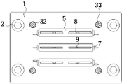
FIG. 1 is a schematic front view of the present invention;
FIG. 2 is a schematic cross-sectional structural view of the present invention;
FIG. 3 is an enlarged view of the structure at A in FIG. 2 according to the present invention;
FIG. 4 is a schematic bottom view of the upper die holder according to the present invention.
In the figure: 1. an upper die holder; 2. a guide post; 3. a telescopic limiting rod; 31. a limiting spring; 32. a circular connecting plate; 33. a trapezoidal anti-skid block; 4. an elastic connecting plate; 5. fixing a bracket; 6. a fixed block; 7. a threaded rod; 8. a cross-shaped sliding block; 9. punching a needle; 10. a lower die holder; 11. a guide bar; 12. a support block; 13. a hollow slab; 14. an exhaust duct; 15. an annular engaging plate; 16. a fixing plate; 17. a waste collection tank; 171. a T-shaped slider; 172. a buffer spring; 173. a rubber buffer plate.
Detailed Description
The technical solutions in the embodiments of the present invention will be clearly and completely described below with reference to the drawings in the embodiments of the present invention, and it is obvious that the described embodiments are only a part of the embodiments of the present invention, and not all of the embodiments. All other embodiments, which can be derived by a person skilled in the art from the embodiments given herein without making any creative effort, shall fall within the protection scope of the present invention.
Referring to fig. 1-4, the present invention provides a technical solution: a sheet forming and blanking die comprises: the device comprises an upper die holder 1, a guide post 2, a telescopic limiting rod 3, a limiting spring 31, a circular connecting plate 32, a trapezoidal antiskid block 33, an elastic connecting plate 4, a fixed support 5, a fixed block 6, a threaded rod 7, a cross-shaped sliding block 8, a punching needle 9, a lower die holder 10, a guide rod 11, a supporting block 12, a hollow plate 13, an exhaust pipe 14, an annular clamping plate 15, a fixed plate 16, a waste collection box 17, a T-shaped sliding block 171, a buffer spring 172 and a rubber buffer plate 173;
the die comprises an upper die holder 1, wherein a guide post 2 is vertically and fixedly connected inside the upper die holder 1 in a penetrating manner, a telescopic limiting rod 3 is fixedly arranged at the top of the upper die holder 1, an elastic connecting plate 4 is fixedly connected at the bottom of the upper die holder 1, a fixed support 5 is fixedly arranged at the bottom of the elastic connecting plate 4, and a fixed block 6 is fixedly connected inside the fixed support 5;
the threaded rod 7 is vertically, penetratingly and rotatably connected to the side of the fixed block 6, a cross-shaped sliding block 8 is movably connected to the outer wall of the threaded rod 7, a punching needle 9 is fixedly connected to the bottom of the cross-shaped sliding block 8, and the punching needle 9 and the fixed support 5 form a sliding structure through the cross-shaped sliding block 8;
the lower die base 10 is arranged at the bottom of the upper die base 1 in parallel, the top of the lower die base 10 is fixedly connected with a guide rod 11, the top of the lower die base 10 is fixedly provided with a supporting block 12, the top of the lower die base 10 is fixedly connected with a hollow plate 13, an exhaust pipe 14 is embedded in the side of the hollow plate 13, and the other side of the hollow plate 13 is fixedly connected with an annular clamping plate 15;
and the fixing plate 16 is fixedly arranged at the bottom of the lower die holder 10, and the side of the fixing plate 16 is connected with a waste collecting box 17 in a front-back sliding manner.
The telescopic limiting rod 3 further comprises:
the limiting spring 31 is fixedly connected to the bottom of the upper die holder 1, the limiting spring 31 is sleeved outside the telescopic limiting rod 3, and the telescopic limiting rod 3 can automatically return through the limiting spring 31;
the circular connecting plate 32 is fixedly connected to the bottom of the telescopic limiting rod 3, and the top of the circular connecting plate 32 is fixedly connected with the bottom of the limiting spring 31;
the trapezoidal anti-skid blocks 33 are fixedly arranged at the bottom of the circular connecting plate 32, and the fixing effect of the telescopic limiting rod 3 is further improved through the arranged trapezoidal anti-skid blocks 33, so that the plate is prevented from being displaced during processing;
the number of the limiting springs 31 is four, every two of the four limiting springs 31 form a group, the two groups of limiting springs 31 are symmetrically arranged by taking the perpendicular bisector of the upper die holder 1 as a symmetry axis, the upper die holder 1 and the circular connecting plate 32 form an elastic structure through the limiting springs 31, and the circular connecting plate 32 can fix plates with more thicknesses through the upper die holder 1 and the circular connecting plate 32 which are arranged into the elastic structure;
the blanking die comprises four guide rods 11, wherein every two of the four guide rods 11 are in one group, the two groups of guide rods 11 are symmetrically arranged by taking a perpendicular bisector of a lower die holder 10 as a symmetry axis, the lower die holder 10 and guide posts 2 form a clamping structure through the guide rods 11, the external dimension of each guide rod 11 is completely matched with the dimension of an internal through hole of each guide post 2, and the blanking die cannot deviate from the direction when punching is carried out on a plate through the lower die holder 10 and the guide posts 2 which are arranged into the clamping structure, so that the situation that the punching needle 9 impacts the top of the lower die holder 10 to cause damage is avoided;
the waste collection box 17 further comprises:
a T-shaped slider 171 fixedly attached to the side of the scrap collecting box 17;
the buffer spring 172 is embedded on the inner wall of the bottom of the waste collection box 17, and the punched waste cannot damage the waste collection box 17 by the arranged buffer spring 172;
a rubber buffer plate 173 fixedly connected to the top of the buffer spring 172, wherein the waste is sufficiently buffered when falling into the waste collection box 17 through the arranged rubber buffer plate 173;
the end of the T-shaped slider 171 is fixedly connected with the side of the waste collection box 17, the waste collection box 17 forms a sliding structure with the fixed plate 16 through the T-shaped slider 171, the other end of the T-shaped slider 171 is attached to the inner surface of the fixed plate 16, and the waste collection box 17 and the fixed plate 16 which are arranged in the sliding structure facilitate the user to take out the waste collection box 17 from the bottom of the lower die holder 10.
The working principle is as follows: when the plate forming blanking die is used, according to fig. 1, 2, 3 and 4, an upper die holder 1 and a lower die holder 10 are preliminarily installed in a punch, then the punch is opened to enable the upper die holder 1 to move towards the lower die holder 10, the positions of the upper die holder 1 and the lower die holder 10 are positioned by inserting a guide rod 11 into a guide post 2, after the positioning is finished, the upper die holder 1 and the lower die holder 10 are firmly fixed in the punch, then an air conveying pipe of an air box is installed on a hollow plate 13 through an annular clamping plate 15, then a threaded rod 7 is rotated, the threaded rod 7 rotates in a fixed block 6, so that a cross-shaped sliding block 8 moves in a fixed support 5, the distance between two punching needles 9 is adjusted, and finally a plate to be punched is placed at the top of a supporting block 12 by a user;
according to the figures 1, 2 and 4, after the plate is placed, the punch press is opened, so that the upper die holder 1 moves downwards, the punching needle 9 at the bottom of the fixed bracket 5 is driven to descend, when the punching needle 9 does not reach the surface of the plate, the circular connecting plate 32 and the trapezoidal anti-skid blocks 33 at the bottom of the telescopic limiting rod 3 contact the top of the plate and limit and fix the plate, then the punching needle 9 continues to move towards the surface of the plate, the influence of the trapezoidal anti-skid blocks 33 on the descending of the upper die holder 1 is avoided through the cooperation of the limiting springs 31 and the telescopic limiting rods 3, when the punching needle 9 punches the plate, the punched waste falls into the waste collection box 17 through the through hole in the lower die holder 10, the waste is prevented from directly falling to damage the waste collection box 17 through the protection of the buffer springs 172 and the rubber buffer plates 173, and simultaneously, the wind in the hollow plate 13 blows towards the plate through the exhaust pipe 14, the punched scraps are removed, the upper die base 1 rises after the punching of the punching needle 9 is finished, the telescopic limiting rod 3 automatically returns through the elastic force of the limiting spring 31, then a worker replaces the plate at the top of the supporting block 12, and finally after the plate is completely processed, a user grasps the waste collection box 17 and slides in the fixing plate 16 through the T-shaped sliding block 171 to draw out the waste collection box 17, and finally, the waste in the waste collection box 17 is uniformly treated.
Those not described in detail in this specification are within the skill of the art.
Although embodiments of the present invention have been shown and described, it will be appreciated by those skilled in the art that changes, modifications, substitutions and alterations can be made in these embodiments without departing from the principles and spirit of the utility model, the scope of which is defined in the appended claims and their equivalents.
Claims (6)
1. The utility model provides a panel shaping blanking mould which characterized in that includes:
the inner part of the upper die base vertically penetrates through and is fixedly connected with a guide post, a telescopic limiting rod is fixedly arranged at the top of the upper die base, an elastic connecting plate is fixedly connected to the bottom of the upper die base, a fixing support is fixedly arranged at the bottom of the elastic connecting plate, and a fixing block is fixedly connected to the inner part of the fixing support;
the threaded rod is vertically, penetratingly and rotatably connected to the side of the fixed block, a cross-shaped sliding block is movably connected to the outer wall of the threaded rod, a punching needle is fixedly connected to the bottom of the cross-shaped sliding block, and the punching needle and the fixed support form a sliding structure through the cross-shaped sliding block;
the lower die base is arranged at the bottom of the upper die base in parallel, the top of the lower die base is fixedly connected with a guide rod, the top of the lower die base is fixedly provided with a supporting block, the top of the lower die base is fixedly connected with a hollow plate, an exhaust pipe is embedded in the side of the hollow plate, and the other side of the hollow plate is fixedly connected with an annular clamping plate;
and the fixing plate is fixedly arranged at the bottom of the lower die seat, and the side edge of the fixing plate is connected with a waste collecting box in a front-back sliding manner.
2. The sheet forming and blanking die of claim 1, wherein: flexible gag lever post still includes:
the limiting spring is fixedly connected to the bottom of the upper die holder and sleeved outside the telescopic limiting rod;
the circular connecting plate is fixedly connected to the bottom of the telescopic limiting rod, and the top of the circular connecting plate is fixedly connected with the bottom of the limiting spring;
and the trapezoidal anti-skidding block is fixedly arranged at the bottom of the circular connecting plate.
3. The sheet forming and blanking die of claim 2, wherein: the quantity of spacing spring is four, and every two of four spacing springs are a set of to the perpendicular bisector of upper die base sets up for symmetry axis symmetry two sets of spacing springs, and the upper die base passes through spacing spring and circular connecting plate constitutes elastic construction moreover.
4. The sheet forming and blanking die of claim 1, wherein: the quantity of guide bar is four, and every two of four guide bar are a set of to two sets of guide bar are the symmetry axis symmetry setting for the perpendicular bisector of lower die holder, and the lower die holder passes through the guide bar and constitutes block structure with the guide post moreover, and the external dimension of guide bar is identical completely with the inside through-hole size of guide post.
5. The sheet forming and blanking die of claim 1, wherein: the scrap collecting box further comprises:
the T-shaped sliding block is fixedly connected to the side of the waste collection box;
the buffer spring is embedded on the inner wall of the bottom of the waste collection box;
and the rubber buffer plate is fixedly connected to the top of the buffer spring.
6. The sheet forming and blanking die of claim 5, wherein: the end part of the T-shaped sliding block is fixedly connected with the side of the waste collection box, the waste collection box forms a sliding structure with the fixed plate through the T-shaped sliding block, and the other end of the T-shaped sliding block is attached to the inner surface of the fixed plate.
Priority Applications (1)
| Application Number | Priority Date | Filing Date | Title |
|---|---|---|---|
| CN202122671699.2U CN216397689U (en) | 2021-11-03 | 2021-11-03 | Plate forming and blanking die |
Applications Claiming Priority (1)
| Application Number | Priority Date | Filing Date | Title |
|---|---|---|---|
| CN202122671699.2U CN216397689U (en) | 2021-11-03 | 2021-11-03 | Plate forming and blanking die |
Publications (1)
| Publication Number | Publication Date |
|---|---|
| CN216397689U true CN216397689U (en) | 2022-04-29 |
Family
ID=81298737
Family Applications (1)
| Application Number | Title | Priority Date | Filing Date |
|---|---|---|---|
| CN202122671699.2U Expired - Fee Related CN216397689U (en) | 2021-11-03 | 2021-11-03 | Plate forming and blanking die |
Country Status (1)
| Country | Link |
|---|---|
| CN (1) | CN216397689U (en) |
Cited By (1)
| Publication number | Priority date | Publication date | Assignee | Title |
|---|---|---|---|---|
| CN116175685A (en) * | 2022-12-13 | 2023-05-30 | 江苏亿尚鸿电子科技有限公司 | Blanking and punching device for lens protection film and using method |
-
2021
- 2021-11-03 CN CN202122671699.2U patent/CN216397689U/en not_active Expired - Fee Related
Cited By (2)
| Publication number | Priority date | Publication date | Assignee | Title |
|---|---|---|---|---|
| CN116175685A (en) * | 2022-12-13 | 2023-05-30 | 江苏亿尚鸿电子科技有限公司 | Blanking and punching device for lens protection film and using method |
| CN116175685B (en) * | 2022-12-13 | 2023-12-15 | 江苏亿尚鸿电子科技有限公司 | Blanking and punching device for lens protection film and using method |
Similar Documents
| Publication | Publication Date | Title |
|---|---|---|
| CN204035343U (en) | A kind of bracket progressive die device | |
| CN204604443U (en) | Shoe-pad cutting mould | |
| CN219597811U (en) | Stamping die | |
| CN210547353U (en) | Gasket locating hole processingequipment | |
| CN220611958U (en) | Stamping die convenient for waste recovery | |
| CN209531845U (en) | A channel steel punching die for textile machinery | |
| CN218168416U (en) | One-step forming die of air filter end cover | |
| CN210450564U (en) | Numerical control stamping die of circular cylinder | |
| CN205110515U (en) | Automation line of pudding mould | |
| CN205324528U (en) | Bearing retainer automatic feeding mechanism | |
| CN210497980U (en) | Novel stamping structure of punching machine | |
| CN207343568U (en) | A kind of waste material collects cover punching die automatically | |
| CN223588136U (en) | Metal photo frame processing and cutting die | |
| CN218361642U (en) | Stamping die with material receiving mechanism | |
| CN221246694U (en) | Elevator link plate punching and trimming die | |
| CN222902289U (en) | Mould is used in processing of circular arc bullet steel core | |
| CN216000726U (en) | Injection molding and punching device for door and window windproof drainage hole cover | |
| CN204262188U (en) | A kind of Novel sheet metal indent bending mould | |
| CN213968624U (en) | Automobile glass riser stamping die | |
| CN221362150U (en) | Automatic discharging device for die material sheets | |
| CN220497575U (en) | Automatic waste discharging device | |
| CN217191971U (en) | Automatic waste discharge device for stamping | |
| CN216176076U (en) | High-precision sheet metal stamping die | |
| CN220782026U (en) | Automobile driving disc punching machine with protection structure | |
| CN111215528A (en) | Novel stamping die |
Legal Events
| Date | Code | Title | Description |
|---|---|---|---|
| GR01 | Patent grant | ||
| GR01 | Patent grant | ||
| CF01 | Termination of patent right due to non-payment of annual fee |
Granted publication date: 20220429 |
|
| CF01 | Termination of patent right due to non-payment of annual fee |