CN216390869U - But angle regulation's solar rack - Google Patents
But angle regulation's solar rack Download PDFInfo
- Publication number
- CN216390869U CN216390869U CN202122487338.2U CN202122487338U CN216390869U CN 216390869 U CN216390869 U CN 216390869U CN 202122487338 U CN202122487338 U CN 202122487338U CN 216390869 U CN216390869 U CN 216390869U
- Authority
- CN
- China
- Prior art keywords
- rod
- solar panel
- solar
- limiting
- rotating
- Prior art date
- Legal status (The legal status is an assumption and is not a legal conclusion. Google has not performed a legal analysis and makes no representation as to the accuracy of the status listed.)
- Active
Links
- 230000005540 biological transmission Effects 0.000 claims description 4
- 230000000149 penetrating effect Effects 0.000 claims description 3
- 230000001174 ascending effect Effects 0.000 claims description 2
- XLYOFNOQVPJJNP-UHFFFAOYSA-N water Substances O XLYOFNOQVPJJNP-UHFFFAOYSA-N 0.000 claims description 2
- 238000009434 installation Methods 0.000 abstract description 13
- 238000004134 energy conservation Methods 0.000 abstract description 3
- 230000003245 working effect Effects 0.000 abstract description 3
- 244000309464 bull Species 0.000 description 6
- 230000005611 electricity Effects 0.000 description 3
- 238000009825 accumulation Methods 0.000 description 2
- 238000004140 cleaning Methods 0.000 description 2
- 238000001125 extrusion Methods 0.000 description 2
- 238000005286 illumination Methods 0.000 description 2
- 230000005855 radiation Effects 0.000 description 2
- 230000009286 beneficial effect Effects 0.000 description 1
- 238000005516 engineering process Methods 0.000 description 1
- 239000000463 material Substances 0.000 description 1
- 238000012986 modification Methods 0.000 description 1
- 230000004048 modification Effects 0.000 description 1
- 238000006467 substitution reaction Methods 0.000 description 1
Images


Classifications
-
- Y—GENERAL TAGGING OF NEW TECHNOLOGICAL DEVELOPMENTS; GENERAL TAGGING OF CROSS-SECTIONAL TECHNOLOGIES SPANNING OVER SEVERAL SECTIONS OF THE IPC; TECHNICAL SUBJECTS COVERED BY FORMER USPC CROSS-REFERENCE ART COLLECTIONS [XRACs] AND DIGESTS
- Y02—TECHNOLOGIES OR APPLICATIONS FOR MITIGATION OR ADAPTATION AGAINST CLIMATE CHANGE
- Y02E—REDUCTION OF GREENHOUSE GAS [GHG] EMISSIONS, RELATED TO ENERGY GENERATION, TRANSMISSION OR DISTRIBUTION
- Y02E10/00—Energy generation through renewable energy sources
- Y02E10/40—Solar thermal energy, e.g. solar towers
- Y02E10/47—Mountings or tracking
-
- Y—GENERAL TAGGING OF NEW TECHNOLOGICAL DEVELOPMENTS; GENERAL TAGGING OF CROSS-SECTIONAL TECHNOLOGIES SPANNING OVER SEVERAL SECTIONS OF THE IPC; TECHNICAL SUBJECTS COVERED BY FORMER USPC CROSS-REFERENCE ART COLLECTIONS [XRACs] AND DIGESTS
- Y02—TECHNOLOGIES OR APPLICATIONS FOR MITIGATION OR ADAPTATION AGAINST CLIMATE CHANGE
- Y02E—REDUCTION OF GREENHOUSE GAS [GHG] EMISSIONS, RELATED TO ENERGY GENERATION, TRANSMISSION OR DISTRIBUTION
- Y02E10/00—Energy generation through renewable energy sources
- Y02E10/50—Photovoltaic [PV] energy
Landscapes
- Photovoltaic Devices (AREA)
Abstract
The utility model discloses an angle-adjustable solar support, which relates to the field of solar supports and comprises a base, wherein a supporting rod is fixed on one side of the top of the base, two groups of rotating rods are arranged on the other side of the top of the base through bearings, a lifting rod is arranged on the top of each rotating rod, a sliding block is arranged at one end, away from the rotating rods, of each lifting rod through a rotating shaft, an installation frame is arranged at the top of each supporting rod through a hinged seat, one side of the top of the installation frame is connected with a group of clamping blocks through the rotating shaft, and a limiting assembly is arranged at the top of each clamping block. The solar energy bracket solves the problem that accumulated snow on the top of the solar panel is not well cleaned by the traditional solar energy bracket, the limiting rod can be driven to slide in the mounting frame by driving the screw rod to rotate through the arranged motor, the purpose that the solar panel is cleaned by the brush is achieved, the problem that the working effect of the solar panel is not good due to accumulated snow on the solar panel is avoided, and the motor is powered through the solar panel, so that energy conservation is achieved.
Description
Technical Field
The utility model relates to the field of solar supports, in particular to a solar support with an adjustable angle.
Background
Solar energy (solar energy) refers to the thermal radiation energy of the sun (see three modes of thermal energy transmission: radiation), mainly represents the solar ray which is commonly called as electricity generation or energy supply for a water heater in the modern, and the solar energy electricity generation is integrated into the daily life of people along with the development of science and technology, becomes a part of the electricity used in the life of people, and is usually installed on the top layer of a building.
Current solar rack is fixed usually, and is different according to the season solar light illumination condition of difference, therefore the angle that solar panel needs is different, and current solar panel all is fixed mounting in the support top, and snow accumulation in the solar panel top that falls when snowing winter moreover needs the manual work to clear up, and is comparatively troublesome, and dangerous.
SUMMERY OF THE UTILITY MODEL
Based on the above, the utility model aims to provide an angle-adjustable solar support, so as to solve the technical problems that the existing solar support is usually fixed and different in solar illumination conditions according to different seasons, so that the required angle of a solar panel is different, the existing solar panel is fixedly arranged above the support, and snow falls off and accumulates above the solar panel in winter, so that the solar panel needs to be manually cleaned, and the solar support is troublesome and dangerous.
In order to achieve the purpose, the utility model provides the following technical scheme: the utility model provides an angle-adjustable's solar rack, includes the base, one side at base top is fixed with the bracing piece, and the opposite side at base top installs two sets of bull sticks through the bearing, the top of bull stick is provided with the lifter, and the lifter keeps away from the one end of bull stick and installs the slider through the pivot, the mounting bracket is installed through articulated seat in the top of bracing piece, and one side at mounting bracket top is connected with a set of block piece through the pivot to the top of block piece is provided with spacing subassembly, solar panel is installed to the top of mounting bracket, and the inside lead screw that is provided with of mounting bracket, the bottom of mounting bracket is provided with the motor, and the output of motor and the one end of lead screw all are fixed with bevel gear, the outer wall cover of lead screw is equipped with the gag lever post, and the top of gag lever post is fixed with the brush.
By adopting the technical scheme, the problem that snow on the top of the solar panel is not well cleaned by the traditional solar support is solved, the limiting rod can be driven to slide in the mounting frame by driving the screw rod to rotate through the arranged motor, the aim of cleaning the solar panel by the brush is realized, the problem that the working effect of the solar panel is not good due to accumulation of snow on the solar panel is avoided, the motor is powered through the solar panel, energy conservation is realized, the problem that the angle of the solar panel is inconvenient to adjust is solved, the ascending rod is driven to move up and down by the rotation of the arranged rotating rod, the angle of the mounting frame is adjusted, two groups of belt pulleys can simultaneously drive the two groups of rotating rods to rotate, the synchronization of the angle adjustment of the solar panel is realized, the solar panel can be conveniently mounted by the arrangement of the limiting component, the limiting of the two groups of limiting blocks is realized by the elasticity of the spring to the two groups of limiting blocks, the inserted bar is prevented from being separated from the mounting frame, so that the solar panel is fixed, the use of bolts is reduced, and the mounting work efficiency is improved.
The limiting assembly comprises an inserting rod penetrating to the top of the clamping block, two groups of limiting blocks are arranged at the bottom of the inserting rod, a spring is fixed between the two groups of limiting blocks, and a fixing rod is fixed at the top of the spring.
Through adopting above-mentioned technical scheme, the setting of spacing subassembly can be convenient for install solar panel, through the setting of two sets of stoppers, can accomplish the spacing to the inserted bar through the spring to the elasticity of two sets of stoppers, prevents that inserted bar and mounting bracket from separating to the realization is fixed solar panel, reduces the use of bolt, improves the work efficiency of installation.
The utility model is further provided with a limiting chute matched with the limiting block in the inserting rod, a chute matched with the fixed rod is arranged in the inserting rod, and a jack matched with the limiting block is arranged in the mounting rack.
Through adopting above-mentioned technical scheme, can make the stopper at its inner wall directional slip through the spacing spout that sets up to can realize fixed to solar panel's installation, can be convenient for stimulate the dead lever through the spout that sets up, thereby move the stopper out in the jack.
The utility model is further provided that the bottom of the lifting rod is provided with an external thread, and the rotating rod is internally provided with an internal thread matched with the external thread.
Through adopting above-mentioned technical scheme, the height of lifter can be adjusted through threaded connection's bull stick and lifter to the completion is to the angle modulation of mounting bracket.
The utility model is further arranged in such a way that two groups of bevel gears are meshed and connected, and the outer wall of the limiting rod is provided with a threaded hole matched with the screw rod.
Through adopting above-mentioned technical scheme, two sets of bevel gears that the meshing is connected can drive the lead screw and rotate, can drive gag lever post reciprocating motion when making the lead screw rotate through the screw hole that sets up.
The utility model is further provided that the outer wall of the bottom of the rotating rod is provided with belt pulleys, and the two groups of belt pulleys are in transmission connection through a belt.
Through adopting above-mentioned technical scheme, can make the bull stick drive another group bull stick when rotating through the belt pulley that sets up and rotate, realize the synchronism of work.
The utility model is further arranged in such a way that the bottom of the mounting rack is provided with a sliding groove matched with the sliding block, and the inside of the mounting rack is provided with a sliding groove matched with the limiting rod.
Through adopting above-mentioned technical scheme, thereby the spout through setting up makes the slider can be at the angle of its inner wall reciprocating sliding regulation mounting bracket, can carry out spacing messenger's gag lever post at the inner wall slip to the gag lever post through the sliding tray that sets up.
In summary, the utility model mainly has the following beneficial effects:
1. according to the solar panel snow cleaning device, the problem that accumulated snow on the top of a solar panel is not well cleaned by a traditional solar support is solved through the arrangement of the motor, the screw rod, the limiting rod and the brush, the screw rod is driven to rotate through the arranged motor, so that the limiting rod can be driven to slide in the mounting frame, the purpose that the brush cleans the solar panel is achieved, the problem that accumulated snow is accumulated on the solar panel and the working effect of the solar panel is not good is avoided, and the motor is powered through the solar panel, so that energy conservation is achieved;
2. according to the solar panel angle adjusting device, the problem that the angle of a solar panel is inconvenient to adjust is solved through the arrangement of the rotating rod, the upper lifting rod is driven to move up and down through the rotation of the rotating rod, so that the angle of the mounting frame is adjusted, the two groups of belt pulleys can drive the two groups of rotating rods to rotate simultaneously, the synchronization of the angle adjustment of the solar panel is realized, the arrangement of the limiting component can facilitate the installation of the solar panel, the limitation of the inserting rod can be completed through the elasticity of the two groups of limiting blocks through the arrangement of the two groups of limiting blocks, the inserting rod is prevented from being separated from the mounting frame, so that the fixing of the solar panel is realized, the use of bolts is reduced, and the installation work efficiency is improved.
Drawings
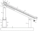
FIG. 1 is a schematic structural view of the present invention;
FIG. 2 is a perspective view of the mount of the present invention;
FIG. 3 is a side view of the mount of the present invention;
FIG. 4 is a schematic view of a bevel gear mesh connection of the present invention;
FIG. 5 is a schematic view of the operation of the spacing assembly of the present invention;
FIG. 6 is a perspective view of the stop block of the present invention.
In the figure: 1. a base; 2. a support bar; 3. a rotating rod; 4. a lifting rod; 5. a slider; 6. a mounting frame; 7. a solar panel; 8. a motor; 9. a limiting component; 901. inserting a rod; 902. a limiting block; 903. a spring; 904. fixing the rod; 10. a screw rod; 11. a limiting rod; 12. a brush; 13. a clamping block; 14. a bevel gear.
Detailed Description
The technical solution in the embodiments of the present invention will be clearly and completely described below with reference to the accompanying drawings in the embodiments of the present invention. The embodiments described below with reference to the accompanying drawings are illustrative only for the purpose of explaining the present invention, and are not to be construed as limiting the present invention.
The following describes an embodiment of the present invention based on its overall structure.
An angle-adjustable solar support is shown in figures 1-5 and comprises a base 1, a support rod 2 is fixed on one side of the top of the base 1, two sets of rotating rods 3 are mounted on the other side of the top of the base 1 through bearings, a lifting rod 4 is arranged on the top of each rotating rod 3, a slider 5 is mounted on one end, far away from each rotating rod 3, of each lifting rod 4 through a rotating shaft, each rotating rod 3 rotates to drive the other set of rotating rods 3 to rotate through a belt pulley, the lifting rods 4 can be driven to move up and down according to the principle of a screw rod, the sliders 5 slide at the bottom of a mounting frame to complete angle adjustment of a solar panel 7, the mounting frame 6 is mounted on the top of the support rod 2 through a hinged seat, one side of the top of the mounting frame 6 is connected with a set of clamping blocks 13 through the rotating shaft, a limiting component 9 is arranged on the top of each clamping block 13, the solar panel 7 is mounted above the mounting frame 6, and a screw rod 10 is arranged inside the mounting frame 6, the bottom of the mounting frame 6 is provided with a motor 8, bevel gears 14 are fixed at the output end of the motor 8 and one end of a screw rod 10, a limiting rod 11 is sleeved on the outer wall of the screw rod 10, a brush 12 is fixed at the top of the limiting rod 11, the motor 8 rotates to drive the bevel gears 14 to rotate, the bevel gears 14 rotate to drive the screw rod 10 to rotate, the limiting rod 11 is driven to move inside the mounting frame when the screw rod 10 rotates according to the screw rod principle, the brush 12 is driven to move when the limiting rod 11 moves, so that accumulated snow on the top of the solar panel 7 is cleaned by the brush 12, the problem of damage of the solar panel due to accumulated snow on the top of the solar panel 7 is avoided, the limiting component 9 comprises an inserting rod 901 penetrating to the top of the clamping block 13, two groups of limiting blocks 902 are arranged at the bottom of the inserting rod 901, springs 903 are fixed between the two groups of limiting blocks 902, a fixing rod 904 is fixed at the top of the springs 903, the solar panel 7 is inserted into the mounting frame 6, rotate block 13, carry out preliminary spacing to solar panel 7 through block 13, insert the jack of inserted bar 9 top block 13 in, two sets of stoppers 902 are by extrusion relative motion to spring 903 in the middle of the extrusion, when the stopper gets into the inside spacing inslot of mounting bracket 6, reset (spring 903 is in by the extruded state) through the elasticity of spring 903 to the stopper, thereby accomplish the installation to solar panel 7, reduce the use of bolt, improve the work efficiency of installation.
Please refer to fig. 5, the inside of the inserting rod 901 is provided with a limiting chute matched with the limiting block 902, and the inside of the inserting rod 901 is provided with a chute matched with the fixing rod 904, the inside of the mounting frame 6 is provided with a jack matched with the limiting block 902, the limiting block 902 can slide in the inner wall of the mounting frame in a directional manner through the set limiting chute, so that the solar panel 7 can be mounted and fixed, the fixing rod 904 can be conveniently pulled through the set chute, and the limiting block 902 can be moved out from the jack.
Referring to fig. 1, the bottom of the lifting rod 4 is provided with an external thread, the rotating rod 3 is internally provided with an internal thread matched with the external thread, and the rotating rod 3 and the lifting rod 4 which are connected through the thread can adjust the height of the lifting rod 4, so that the angle adjustment of the mounting rack 6 is completed.
Referring to fig. 4, two sets of bevel gears 14 are engaged with each other, a threaded hole matched with the screw rod 10 is formed in the outer wall of the limiting rod 11, the two sets of bevel gears 14 engaged with each other can drive the screw rod 10 to rotate, and the screw rod 10 can drive the limiting rod 11 to reciprocate when rotating through the threaded hole.
Referring to fig. 1, the outer wall of the bottom of the rotating rod 3 is provided with belt pulleys, two groups of belt pulleys are in transmission connection through a belt, and the rotating rod 3 can drive the other group of rotating rod 3 to rotate when rotating through the arranged belt pulleys, so that the working synchronism is realized.
Referring to fig. 1, the bottom of the mounting frame 6 is provided with a sliding groove matched with the sliding block 5, the mounting frame 6 is provided inside with a sliding groove matched with the limiting rod 11, the sliding block 5 can slide in a reciprocating manner on the inner wall of the sliding groove to adjust the angle of the mounting frame 6, and the limiting rod 11 can be limited by the sliding groove so that the limiting rod 11 slides on the inner wall.
The working principle of the utility model is as follows: when the solar panel 7 is installed, the solar panel 7 is inserted into the upper part of the installation frame 6, the clamping block 13 is rotated, the solar panel 7 is preliminarily limited through the clamping block 13, the inserting rod 9 is inserted into the jack above the clamping block 13, the two groups of limiting blocks 902 are extruded to move relatively, so that the middle spring 903 is extruded, when the limiting blocks enter the limiting grooves in the installation frame 6, the elastic force of the limiting blocks is reset through the spring 903 (the spring 903 is in an extruded state), thereby the installation of the solar panel 7 is completed, the use of bolts is reduced, the installation work efficiency is improved, when the angle of the solar panel 7 is adjusted according to different seasons, the rotating rod 3 is rotated to drive the other group of rotating rods 3 to rotate through the belt pulley, the lifting rod 4 can be driven to move up and down according to the principle of the screw rod, at the moment, the sliding block 5 slides at the bottom of the installation frame to complete the angle adjustment of the solar panel 7, when snowing in winter, open motor 8, motor 8 rotates and drives bevel gear 14 and rotate, and bevel gear 14 drives lead screw 10 when rotating and rotates, drives gag lever post 11 when rotating according to lead screw principle lead screw 10 and removes in the mounting bracket is inside, drives brush 12 when gag lever post 11 removes to realize brush 12 and clear up the snow at solar panel 7 top, avoid snow to pile up the problem that causes solar panel to damage in solar panel 7's top.
Although embodiments of the present invention have been shown and described, the present embodiments are merely illustrative of the present invention and are not intended to limit the present invention, and the described specific features, structures, materials or characteristics may be combined in any suitable manner in any one or more embodiments or examples, and those skilled in the art can make modifications, substitutions, variations, etc. of the embodiments as required without departing from the principle and spirit of the present invention, but within the scope of the claims of the present invention.
Claims (7)
1. The utility model provides an angle-adjustable's solar rack, includes base (1), its characterized in that: the solar energy water heater is characterized in that a supporting rod (2) is fixed on one side of the top of the base (1), two groups of rotating rods (3) are mounted on the other side of the top of the base (1) through bearings, a lifting rod (4) is arranged on the top of each rotating rod (3), a sliding block (5) is mounted at one end, away from the rotating rods (3), of each lifting rod (4) through a rotating shaft, a mounting frame (6) is mounted at the top of each supporting rod (2) through a hinged seat, a group of clamping blocks (13) are connected to one side of the top of the mounting frame (6) through the rotating shaft, a limiting component (9) is arranged at the top of each clamping block (13), a solar panel (7) is mounted above the mounting frame (6), a lead screw (10) is arranged inside the mounting frame (6), a motor (8) is arranged at the bottom of the mounting frame (6), and bevel gears (14) are fixed at the output end of the motor (8) and one end of the lead screw (10), the outer wall cover of lead screw (10) is equipped with gag lever post (11), and the top of gag lever post (11) is fixed with brush (12).
2. An adjustable angle solar rack as defined in claim 1, wherein: the limiting assembly (9) comprises an inserting rod (901) penetrating to the top of the clamping block (13), two groups of limiting blocks (902) are arranged at the bottom of the inserting rod (901), a spring (903) is fixed between the two groups of limiting blocks (902), and a fixing rod (904) is fixed at the top of the spring (903).
3. An adjustable angle solar rack as defined in claim 2, wherein: the inside of inserted bar (901) is provided with spacing spout of stopper (902) assorted, and the inside of inserted bar (901) is provided with dead lever (904) assorted spout, the inside of mounting bracket (6) is seted up with stopper (902) assorted jack.
4. An adjustable angle solar rack as defined in claim 1, wherein: the bottom of the ascending rod (4) is provided with an external thread, and the inside of the rotating rod (3) is provided with an internal thread matched with the external thread.
5. An adjustable angle solar rack as defined in claim 1, wherein: the two groups of bevel gears (14) are connected in a meshed mode, and threaded holes matched with the screw rods (10) are formed in the outer wall of the limiting rod (11).
6. An adjustable angle solar rack as defined in claim 1, wherein: the outer wall of the bottom of the rotating rod (3) is provided with belt pulleys, and the two groups of belt pulleys are connected through belt transmission.
7. An adjustable angle solar rack as defined in claim 1, wherein: the bottom of the mounting rack (6) is provided with a sliding groove matched with the sliding block (5), and the inside of the mounting rack (6) is provided with a sliding groove matched with the limiting rod (11).
Priority Applications (1)
| Application Number | Priority Date | Filing Date | Title |
|---|---|---|---|
| CN202122487338.2U CN216390869U (en) | 2021-10-15 | 2021-10-15 | But angle regulation's solar rack |
Applications Claiming Priority (1)
| Application Number | Priority Date | Filing Date | Title |
|---|---|---|---|
| CN202122487338.2U CN216390869U (en) | 2021-10-15 | 2021-10-15 | But angle regulation's solar rack |
Publications (1)
| Publication Number | Publication Date |
|---|---|
| CN216390869U true CN216390869U (en) | 2022-04-26 |
Family
ID=81245447
Family Applications (1)
| Application Number | Title | Priority Date | Filing Date |
|---|---|---|---|
| CN202122487338.2U Active CN216390869U (en) | 2021-10-15 | 2021-10-15 | But angle regulation's solar rack |
Country Status (1)
| Country | Link |
|---|---|
| CN (1) | CN216390869U (en) |
Cited By (1)
| Publication number | Priority date | Publication date | Assignee | Title |
|---|---|---|---|---|
| CN119675550A (en) * | 2024-11-11 | 2025-03-21 | 广东和发能源科技集团有限公司 | A fixed solar power generation array bracket |
-
2021
- 2021-10-15 CN CN202122487338.2U patent/CN216390869U/en active Active
Cited By (1)
| Publication number | Priority date | Publication date | Assignee | Title |
|---|---|---|---|---|
| CN119675550A (en) * | 2024-11-11 | 2025-03-21 | 广东和发能源科技集团有限公司 | A fixed solar power generation array bracket |
Similar Documents
| Publication | Publication Date | Title |
|---|---|---|
| CN111245341B (en) | Solar photovoltaic panel installing support with automatically regulated function | |
| CN211232697U (en) | Adjustable solar street lamp | |
| CN119696483A (en) | Energy-saving photovoltaic bracket assembly with adjustable angle | |
| CN111900926A (en) | A cleaning device and solar lamps | |
| CN117478042A (en) | An adjustable integrated bracket structure for household photovoltaic power generation | |
| CN120760079A (en) | A street light pole device with a liftable arm for multiple scenarios and its operation method | |
| CN221283103U (en) | Photovoltaic mounting frame with wind-resistant structure | |
| CN215072272U (en) | Installing support for solar energy power generation | |
| CN215734155U (en) | Solar panel supporting structure for photovoltaic power generation | |
| CN211424207U (en) | LED outdoor illuminating lamp with adjustable illuminating angle | |
| CN216599488U (en) | But angle regulation's solar photovoltaic is support frame for board | |
| CN214380770U (en) | Adjustable solar panel with high daylighting rate | |
| CN216158963U (en) | Environment self-adaptive solar LED street lamp | |
| CN212273881U (en) | Environment-friendly energy-saving LED street lamp with good stability | |
| CN111120974A (en) | Solar cell panel for street lamp | |
| CN221728252U (en) | Aluminum frame convenient to clean photovoltaic power generation board | |
| CN216565019U (en) | Efficient photovoltaic module with more intensive land | |
| CN221463760U (en) | Solar street lamp bracket with adjustable lighting angle | |
| CN222192280U (en) | Solar panel self-cleaning support | |
| CN221098504U (en) | Office lamp with adjustable illumination position | |
| CN220601275U (en) | Municipal solar lighting device | |
| CN113783518A (en) | Photovoltaic board installing support welding frock | |
| CN220915215U (en) | Intelligent building energy-saving device | |
| CN223873426U (en) | Solar full-automatic sunshade umbrella | |
| CN220139504U (en) | Photovoltaic module with bird repellent function |
Legal Events
| Date | Code | Title | Description |
|---|---|---|---|
| GR01 | Patent grant | ||
| GR01 | Patent grant |